EP1086792A1 - Dispositif de fixation empilable destiné au coffrage - Google Patents
Dispositif de fixation empilable destiné au coffrage Download PDFInfo
- Publication number
- EP1086792A1 EP1086792A1 EP00120726A EP00120726A EP1086792A1 EP 1086792 A1 EP1086792 A1 EP 1086792A1 EP 00120726 A EP00120726 A EP 00120726A EP 00120726 A EP00120726 A EP 00120726A EP 1086792 A1 EP1086792 A1 EP 1086792A1
- Authority
- EP
- European Patent Office
- Prior art keywords
- fixing device
- cover
- hood
- cover part
- magnet body
- Prior art date
- Legal status (The legal status is an assumption and is not a legal conclusion. Google has not performed a legal analysis and makes no representation as to the accuracy of the status listed.)
- Granted
Links
- 238000009416 shuttering Methods 0.000 title description 5
- 238000009415 formwork Methods 0.000 claims abstract description 40
- 230000005294 ferromagnetic effect Effects 0.000 claims abstract description 4
- 230000005291 magnetic effect Effects 0.000 claims description 49
- 230000006835 compression Effects 0.000 claims description 9
- 238000007906 compression Methods 0.000 claims description 9
- 239000000463 material Substances 0.000 claims description 5
- 229910001220 stainless steel Inorganic materials 0.000 claims description 5
- 239000010935 stainless steel Substances 0.000 claims description 5
- 230000000149 penetrating effect Effects 0.000 claims description 2
- 239000004567 concrete Substances 0.000 description 4
- 239000007788 liquid Substances 0.000 description 4
- 239000011178 precast concrete Substances 0.000 description 4
- 239000000853 adhesive Substances 0.000 description 3
- 230000001070 adhesive effect Effects 0.000 description 3
- 230000008901 benefit Effects 0.000 description 3
- 238000013461 design Methods 0.000 description 3
- 238000003860 storage Methods 0.000 description 3
- 238000012549 training Methods 0.000 description 3
- 239000006096 absorbing agent Substances 0.000 description 2
- 230000000295 complement effect Effects 0.000 description 2
- 238000010276 construction Methods 0.000 description 2
- 230000000694 effects Effects 0.000 description 2
- 238000004519 manufacturing process Methods 0.000 description 2
- 239000002184 metal Substances 0.000 description 2
- 230000035939 shock Effects 0.000 description 2
- 125000006850 spacer group Chemical group 0.000 description 2
- 230000000087 stabilizing effect Effects 0.000 description 2
- 230000004308 accommodation Effects 0.000 description 1
- 230000015572 biosynthetic process Effects 0.000 description 1
- 230000008859 change Effects 0.000 description 1
- 230000008878 coupling Effects 0.000 description 1
- 238000010168 coupling process Methods 0.000 description 1
- 238000005859 coupling reaction Methods 0.000 description 1
- 230000005347 demagnetization Effects 0.000 description 1
- 238000011161 development Methods 0.000 description 1
- 238000012432 intermediate storage Methods 0.000 description 1
- 230000007246 mechanism Effects 0.000 description 1
- 238000000034 method Methods 0.000 description 1
- 230000035515 penetration Effects 0.000 description 1
- 230000002093 peripheral effect Effects 0.000 description 1
- 230000008569 process Effects 0.000 description 1
- 230000006641 stabilisation Effects 0.000 description 1
- 238000011105 stabilization Methods 0.000 description 1
- 239000000725 suspension Substances 0.000 description 1
- 238000012546 transfer Methods 0.000 description 1
Images


Classifications
-
- B—PERFORMING OPERATIONS; TRANSPORTING
- B28—WORKING CEMENT, CLAY, OR STONE
- B28B—SHAPING CLAY OR OTHER CERAMIC COMPOSITIONS; SHAPING SLAG; SHAPING MIXTURES CONTAINING CEMENTITIOUS MATERIAL, e.g. PLASTER
- B28B7/00—Moulds; Cores; Mandrels
- B28B7/0002—Auxiliary parts or elements of the mould
- B28B7/0014—Fastening means for mould parts, e.g. for attaching mould walls on mould tables; Mould clamps
- B28B7/0017—Fastening means for mould parts, e.g. for attaching mould walls on mould tables; Mould clamps for attaching mould walls on mould tables
-
- B—PERFORMING OPERATIONS; TRANSPORTING
- B28—WORKING CEMENT, CLAY, OR STONE
- B28B—SHAPING CLAY OR OTHER CERAMIC COMPOSITIONS; SHAPING SLAG; SHAPING MIXTURES CONTAINING CEMENTITIOUS MATERIAL, e.g. PLASTER
- B28B7/00—Moulds; Cores; Mandrels
- B28B7/0002—Auxiliary parts or elements of the mould
- B28B7/0014—Fastening means for mould parts, e.g. for attaching mould walls on mould tables; Mould clamps
- B28B7/002—Fastening means for mould parts, e.g. for attaching mould walls on mould tables; Mould clamps using magnets
-
- E—FIXED CONSTRUCTIONS
- E04—BUILDING
- E04G—SCAFFOLDING; FORMS; SHUTTERING; BUILDING IMPLEMENTS OR AIDS, OR THEIR USE; HANDLING BUILDING MATERIALS ON THE SITE; REPAIRING, BREAKING-UP OR OTHER WORK ON EXISTING BUILDINGS
- E04G11/00—Forms, shutterings, or falsework for making walls, floors, ceilings, or roofs
- E04G11/36—Forms, shutterings, or falsework for making walls, floors, ceilings, or roofs for floors, ceilings, or roofs of plane or curved surfaces end formpanels for floor shutterings
- E04G11/365—Stop-end shutterings
-
- E—FIXED CONSTRUCTIONS
- E04—BUILDING
- E04G—SCAFFOLDING; FORMS; SHUTTERING; BUILDING IMPLEMENTS OR AIDS, OR THEIR USE; HANDLING BUILDING MATERIALS ON THE SITE; REPAIRING, BREAKING-UP OR OTHER WORK ON EXISTING BUILDINGS
- E04G15/00—Forms or shutterings for making openings, cavities, slits, or channels
- E04G15/06—Forms or shutterings for making openings, cavities, slits, or channels for cavities or channels in walls of floors, e.g. for making chimneys
- E04G15/063—Re-usable forms
-
- E—FIXED CONSTRUCTIONS
- E04—BUILDING
- E04G—SCAFFOLDING; FORMS; SHUTTERING; BUILDING IMPLEMENTS OR AIDS, OR THEIR USE; HANDLING BUILDING MATERIALS ON THE SITE; REPAIRING, BREAKING-UP OR OTHER WORK ON EXISTING BUILDINGS
- E04G17/00—Connecting or other auxiliary members for forms, falsework structures, or shutterings
- E04G17/04—Connecting or fastening means for metallic forming or stiffening elements, e.g. for connecting metallic elements to non-metallic elements
Definitions
- the invention relates to a fixing device for formwork purposes, the one Cover and a magnetic holding body, which within the Cover hood arranged, via connecting means with a cover part of the Cover hood coupled and relative to the cover part in the area of Canopy opening is feasible.
- the latter is opposite assigned ferromagnetic formwork underlay to or from which Holding magnet body as part of its leadership depending on the relative position the lid part is attached or detached.
- the invention further relates to a Stack with a plurality of such fixing devices.
- a fixing device of this type is known for avoiding openings in precast concrete parts (DE-A-195 07 506 A1).
- the resilient deflectability of the cover part of the cover is also used as a spring element to press the all-round contact surface of the cover side walls associated with a formwork panel in cooperation with the magnetic body even more firmly against the formwork panel. This should ensure that liquid concrete cannot penetrate into the cavity below the hood.
- the deflection or spring constant of the cover part largely depends on the geometric dimensions, in particular on the width or the diameter of the cover. If the cover or its cover part is quite narrow, this results in an extraordinary hard "spring element with corresponding spring constant. The deflection path that can be achieved is naturally very small with the cover part of the cover hood.
- From DE-U-92 18 032.9 is a reusable recess device for the production of precast concrete known.
- the facility has one Recess body and at least one in the area of the top surface attached magnets. This or more magnets are opposite to that Recess body freely guided in a limited range of motion or held adjustable.
- the magnet has at least one Spring acted against a bore in the recess body supported on a metal tray surrounding the magnet.
- a formwork system for precast concrete parts is also known (WO 97/06 324), at the formwork parts a lifting bracket overlapping the magnetic body exhibit. On the side of the Magnetic body, there is a gap between this and the lifting bracket, in the the magnetic body is retractable if it is from its liability to the Formwork underlay to be solved.
- the magnetic body has a Bore in which a lifting rod supported on the lifting bracket engages, which passes through the magnetic body to the formwork base and the Detachment from the formwork base. The detachment is still through Interposition of a spring in the support point between the lifting rod head and the top of the lifting bracket.
- this is not one Contributed to this, the footprints of the side walls of the cover to press firmly against the formwork panel and thus penetration of liquid concrete in the cavity inside the hood reliably prevent.
- the invention is based, an equally as Recessing device and fastening device for formwork parts to create suitable fixation device in which ease of use and safe and effective functioning is guaranteed.
- a Tension the cover of the fixing device against the formwork support with increased tightness against liquid concrete and a support of the Lifting of the magnetic holding body from the formwork support.
- the solution is in a fixing device with the aforementioned Features proposed according to the invention that between the cover part and the holding magnet body as a connecting means one or more, individual Spring elements switched on and aligned so that they touch down of the holding magnet body on the formwork support in the direction of Hood opening are deflectable.
- the preferably made separately Components for the spring elements are at least functionally between interposed the cover part and the holding magnet body. Because theirs Deflection direction penetrating the hood opening is effective and stable Guide the holding magnet body within the cover to and from the Hood opening concerned. On the one hand, this enables reliable adhesion of the holding magnet body on the ferromagnetic formwork base guarantee because the adhesive force is generally much greater than that opposite spring force.
- the holding magnet body can also be used additional force is released from the formwork base and lighter Handling to be moved towards the bottom of the hood cover part.
- Spring elements are deflected from their idle state, they pull the Hood cover part against the formwork underlay, creating the contact areas be pressed on the narrow or underside of the hood walls. With the the resulting clamping function allows a high level of tightness in the area reach the footprint compared to liquid concrete.
- Individual spring components are used, they can be targeted depending on Select the boundary conditions for the use of the fixing device.
- they can be selected spring elements whose spring constants in view are appropriately dimensioned for the application requirements. For example, lets make sure that the spring elements and spring constants so are dimensioned such that a deflection stroke and a spring force are sufficient in each case to ensure a reliable lifting function for the holding magnet body are ensured.
- this is or they are Spring elements realized as tension springs and inside the cover housed. They are on the one hand on the inside of the cover part and on the other hand on the opposite top of the magnetic holding body attached.
- This has the advantage that compact design and a space-saving accommodation of the spring elements is achieved, and this before external influences are protected.
- the spring elements as Shock absorbers and spacers also serve when the holding magnet body must be reset from the formwork underlay.
- the spring element or elements as Realize compression springs when the magnetic body adheres to the Formwork underlay not (as after the aforementioned training) pulled apart, but pressed together.
- the bolt thus serves as a coupling member between the protruding free end of the compression spring and the holding magnet body.
- the spring elements are with a cylindrical basic shape and arranged so that the cylindrical Longitudinal axis (in imaginary extension) penetrates the hood opening.
- cylindrical spring elements can be easily manufactured and / or easily and inexpensively.
- the cover has an elongated basic shape in which the length is greater and / or is a multiple of the width of the top of the cover.
- This form is useful to fix formwork walls and other formwork parts on the formwork base.
- the spring constant for the resilient tensioning of the cover hood on the formwork support can be specifically adjusted by the selection of the spring elements.
- a slight width of the lid part, which in the prior art mentioned at the beginning hard "pen could lead to the invention by choosing one soft "spring element can be compensated.
- loads, the risk of permanent deformation or other wear for the cover part of the cover are avoided with a small span or width.
- a fixing device with the features mentioned in the context of an alternative invention suggested that the cover be opposite each other Has sidewalls, each with at least one on the Hood opening adjacent edge section from each other to the outside diverge.
- the lower ends of the hood side walls are therefore expedient spread apart. This creates towards the inside of the hood on the Hood opening an approximately wedge-like narrowing cross section with which Place a cover on the (upper) cover part of one below located cover a centering and thus stabilizing holding and Stacking effect is achieved.
- the side walls with their overall cross-sectional shape diverge from each other.
- the side walls are (mainly) parallel to each other run, and only in the lower, peripheral position the edge sections of the opposite side walls at an obtuse angle from each other connect diverging.
- a plurality of generic fixing devices can still be stack more stable on top of each other when handling the above Puller, particularly in the form of an operating handle, one to the outside or top-facing support surface or surface on which an (upper) Fixing device can be placed.
- the support side preferably has a flat-even course.
- the head start of the Operating handle or the handle of the cover part of the (lower) Fixing device is dimensioned so that the operating handle with handle together with the cover part underneath completely through the bottom opening the cover of the upper, attached fixing device is receivable.
- the general inventive idea is a stack of several fixing devices of the aforementioned type proposed, each with a fixing device with Hood opening on the cover part of the one just below Fixing device is placed, and the opposite, diverging Sidewall edge sections of the upper fixing device with their inner sides the ceiling part of the cover of the lower fixing device and / or its upper outer edges between the cover part and the opposite Include sidewalls.
- a centering and stabilization by the The above-mentioned wedge-like cross-sectional shape in the area of the bottom Hood opening of the respective upper fixing device is reached, which is wedge-like Cross-sectional shape through the divergent edge sections of the opposite lying hood side walls is generated.
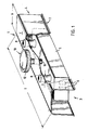
- the fixing device is designed as a shuttering system and with an elongated cover 1 designed with a cuboid basic shape.
- the Cover 1 has a hood opening 2 on the bottom and open end faces 3 and 4, which results in a U-shaped cross-sectional profile.
- a holding magnet body 5 in which individual magnetic elements 6 are cast in plastic. This protects the magnetic body 5 against impacts that could lead to demagnetization.
- the the magnetic elements 6 surrounding or embedding plastic gives the Magnetic body 5 has a low weight, which is advantageous for handling and Occupational safety affects.
- this construction distinguishes the Holding magnet body 5 by a high adhesive force in the area of Hood opening 2 attached formwork underlay.
- the width b of the upper cover part 7 of the cover 1 is several times smaller than the length l.
- This results in the Cover part 7 has a high resistance to transverse deflections.
- a sufficiently resiliently deflectable suspension of the magnetic body 5 to reach the underside of the cover part 7 are between the latter and the top of the magnetic body 5 in the example two cylindrical Elastic tension springs 8 attached to their respective front ends.
- the Magnetic body 5 in its detention position to rest on a formwork support shown the tension springs 8 deflected from their rest position and strongly on Train are loaded. This is shown in a medium cross-sectional constriction 9, which the tension springs are subject to.
- the combination of the cover 1 and the magnetic body 5 with the tension springs 8 leads to a shuttering system, which can be installed in different formwork. It is special for the production of filigree or double walls and lattice girder ceilings suitable.
- the magnetic body 5 engages on the upper side thereof Puller 10 arranged, which one in the magnetic body 5th has screwed-in external thread bolt 11. This enforces the Cover part 7 freely movable and ends in a mushroom-like or plate-like Extension that preferably a non-magnetizable control knob 12 Stainless steel forms.
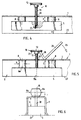
- the magnetic body 5 can be removed from its detention position solve and - with the effective support of the tension springs 8 - in one in Transfer cover 1 to the retracted position according to FIGS. 2-4.
- the tension springs 8 are on their bottom face provided with a projecting screw bolt 13 and above in a complementary internal threaded hole of the magnet body 5 screwed and attached. Furthermore, the tension spring 8 is on its upper and bottom end each provided with a metal end plate 14, 15. The upper end plate 15 is formed in the central area with an internal thread recess 16 into which a fastening screw 17 is screwed in and the cover part 7 of the Cover 1 for attachment to the upper end plate 15 of the tension spring 8 engages behind.
- the two end plates 14, 15 on each end of the tension spring 8 ensure that their cross-section at the front ends even under tensile load does not change significantly.
- the cover part For the free passage of the Fastening screws 17 for the respective tension spring 8 and the External threaded bolt 11 of the puller 10 is the cover part with provided correspondingly assigned mounting holes 18 and 19 respectively.
- the longitudinal side walls 20a, 20b on both sides of the Cover 1 starting from the cover part parallel side wall sections P and at the bottom end 21a, 21b through an obtuse angle w to the outside diverging, sloping edge sections S. From the footprint 22 one The magnetic body in the non-stick position shown in FIG. 3 has formwork underlay a distance A.
- the magnetic body 5 has the same non-stick position with the distance A in FIG Representation of Figure 4.
- the puller 10 is with his External threaded bolt 11 in a complementary threaded bore 23 in the Screwed top of the magnetic body 5.
- the magnetic body 5 is in its adhesive position on the Footprint 22 shown, for example, by a (not shown) Formwork underlay can be formed.
- the spring elements 8 are under Tensile load and are subject to the cross-sectional constriction 9 explained above distance A explained above between the underside of the magnetic body 5 and the Footprint is no longer available.
- FIG. 4 there is only a correspondingly smaller distance e available.
- the puller 10 can be easily in the position shown in Figure 5 actuate by a lifting bracket 24 by this a torque 25 in Direction to the cover part 7 is given.
- FIG. 6 is a compression spring 8b on the upper or Arranged outside of the cover part of the cover.
- the compression spring 8b is penetrated by a connecting bolt 28, the lower end of the Magnetic body 5, and its upper end on the upper end plate 15 of the Compression spring 8b is attached.
- the magnetic body 5 adheres the footprint 22, the increased distance E to the bottom of the Cover part 7 has.
- the compression spring 8b is loaded under pressure, which leads to leads to the cross-sectional bulge 9b indicated in FIG.
- three fixing devices according to the invention are, for example over the centering edge sections S of the longitudinal side walls 20a, 20b of their each cover 1 placed on top of each other.
- the inclines include Edge sections S or bottom ends 21a, 21b the upper edges 29a, 29b the respective lower cover 1 between the cover part 7 and the parallel Sidewall sections P.
- the respective undersides of upper magnetic bodies 5 lie on the outwardly facing upper side 30 of the control knob 12; to
- the control knob 12 has a flat, flat upper side 30 designed, as it were a stabilizing support plate for the Magnetic body 5 of the respective upper, attached fixing device forms.
- control knob made of non-magnetizable material, preferably non-magnetic stainless steel, is formed, the superimposed Detach and remove fixation devices from each other again without any problems.
- the from Cover part 7 projecting section of the external thread bolt 11 is so dimensioned or adjusted that the top 30 of the control knob 12 a Height difference 31 compared to the top of the cover part 7, which about the above distance A of the magnetic body 5 in its non-stick position from a formwork support and / or from the hood opening 2 corresponds to which of the diverging side wall edge sections S is limited.
- the best is the height difference 31 over the corresponding one Rotation of the external thread bolt 11 is set so that when the Magnetic body 5 on the top 30 of the control knob 12, the inside of oblique, diverging edge sections S on the upper edges 29a, 29b Edition come.
- the control knob 12 of the lower fixing device can together with the projecting section of the external thread bolt 11 completely in the Cover 1 of the upper fixation device, because the The diameter of the control knob 12 is smaller than the distance between the hood side walls 20a, 20b from each other.
Landscapes
- Engineering & Computer Science (AREA)
- Architecture (AREA)
- Mechanical Engineering (AREA)
- Civil Engineering (AREA)
- Structural Engineering (AREA)
- Manufacturing & Machinery (AREA)
- Chemical & Material Sciences (AREA)
- Ceramic Engineering (AREA)
- Moulds, Cores, Or Mandrels (AREA)
- Portable Nailing Machines And Staplers (AREA)
Applications Claiming Priority (4)
| Application Number | Priority Date | Filing Date | Title |
|---|---|---|---|
| DE19945752 | 1999-09-24 | ||
| DE19945752 | 1999-09-24 | ||
| DE10002993A DE10002993A1 (de) | 1999-09-24 | 2000-01-24 | Stapelbare Fixiervorrichtung für Schalungszwecke |
| DE10002993 | 2000-01-24 |
Publications (2)
| Publication Number | Publication Date |
|---|---|
| EP1086792A1 true EP1086792A1 (fr) | 2001-03-28 |
| EP1086792B1 EP1086792B1 (fr) | 2002-04-24 |
Family
ID=26004003
Family Applications (1)
| Application Number | Title | Priority Date | Filing Date |
|---|---|---|---|
| EP00120726A Expired - Lifetime EP1086792B1 (fr) | 1999-09-24 | 2000-09-22 | Dispositif de fixation empilable destiné au coffrage |
Country Status (4)
| Country | Link |
|---|---|
| EP (1) | EP1086792B1 (fr) |
| AT (1) | ATE216647T1 (fr) |
| DE (1) | DE20020656U1 (fr) |
| ES (1) | ES2172496T3 (fr) |
Cited By (5)
| Publication number | Priority date | Publication date | Assignee | Title |
|---|---|---|---|---|
| US7175153B2 (en) | 2001-12-06 | 2007-02-13 | Bt Baubedarf Magdeburg Gmbh | Positioning aid |
| EP2199047A3 (fr) * | 2008-12-16 | 2011-08-03 | Sommer Anlagentechnik GmbH | Coffrage de bordure |
| DE102011003667A1 (de) | 2011-02-04 | 2012-08-09 | BETA Maschinenbau GmbH & Co. KG | Magneteinheit |
| DE102011003671A1 (de) | 2011-02-04 | 2012-08-09 | BETA Maschinenbau GmbH & Co. KG | Schalungsträger und Schalungsanordnung |
| WO2012113088A1 (fr) * | 2011-02-23 | 2012-08-30 | Pino Albanese | Équerre de fixation pour coffrages pour bordures de plancher |
Families Citing this family (1)
| Publication number | Priority date | Publication date | Assignee | Title |
|---|---|---|---|---|
| CN112627506B (zh) * | 2020-12-31 | 2021-12-14 | 东晟兴诚集团有限公司 | 一种塑性建筑模板及其支撑装置 |
Citations (5)
| Publication number | Priority date | Publication date | Assignee | Title |
|---|---|---|---|---|
| DE9218032U1 (de) | 1991-05-04 | 1993-06-03 | MTK-Magnettechnik GmbH & Co. KG, 5650 Solingen | Aussparungseinrichtung |
| DE19507506A1 (de) | 1994-11-07 | 1996-05-09 | Georg Weidner | Vorrichtung zum Aussparen von Durchbrüchen in Betonfertigteilen |
| WO1997006324A1 (fr) | 1995-08-04 | 1997-02-20 | Reymann Technik Gmbh | Systeme de coffrage pour pieces prefabriquees en beton |
| DE4129368C2 (de) | 1991-09-04 | 1997-09-11 | Weckenmann Anlagentechnik Gmbh | Einrichtung zur Herstellung von Betonfertigteilen |
| DE19903819A1 (de) * | 1999-02-02 | 2000-08-03 | Reymann Technik Gmbh | Schalungssystem für Betonfertigteile |
-
2000
- 2000-09-22 DE DE20020656U patent/DE20020656U1/de not_active Expired - Lifetime
- 2000-09-22 EP EP00120726A patent/EP1086792B1/fr not_active Expired - Lifetime
- 2000-09-22 AT AT00120726T patent/ATE216647T1/de not_active IP Right Cessation
- 2000-09-22 ES ES00120726T patent/ES2172496T3/es not_active Expired - Lifetime
Patent Citations (5)
| Publication number | Priority date | Publication date | Assignee | Title |
|---|---|---|---|---|
| DE9218032U1 (de) | 1991-05-04 | 1993-06-03 | MTK-Magnettechnik GmbH & Co. KG, 5650 Solingen | Aussparungseinrichtung |
| DE4129368C2 (de) | 1991-09-04 | 1997-09-11 | Weckenmann Anlagentechnik Gmbh | Einrichtung zur Herstellung von Betonfertigteilen |
| DE19507506A1 (de) | 1994-11-07 | 1996-05-09 | Georg Weidner | Vorrichtung zum Aussparen von Durchbrüchen in Betonfertigteilen |
| WO1997006324A1 (fr) | 1995-08-04 | 1997-02-20 | Reymann Technik Gmbh | Systeme de coffrage pour pieces prefabriquees en beton |
| DE19903819A1 (de) * | 1999-02-02 | 2000-08-03 | Reymann Technik Gmbh | Schalungssystem für Betonfertigteile |
Non-Patent Citations (1)
| Title |
|---|
| REYMANN A ET AL: "INTELLIGENTES SCHALEN FLAECHIGER BETONFERTIGTEILE - EINE TECHNISCH-OEKONOMISCHE HERAUSFORDERUNG. INTELLIGENT SHUTTERING FOR FLAT- SURFACED PRECAST CONCRETE COMPONENTS - A CHALLENGE FOR ENGINEERING AND ECONOMIC EFFICIENCY", BETONWERK + FERTIGTEIL TECHNIK,DE,BAUVERLAG GMBH. WIESBADEN, vol. 64, no. 10, 1 October 1998 (1998-10-01), pages 48 - 52, XP000785497, ISSN: 0373-4331 * |
Cited By (7)
| Publication number | Priority date | Publication date | Assignee | Title |
|---|---|---|---|---|
| US7175153B2 (en) | 2001-12-06 | 2007-02-13 | Bt Baubedarf Magdeburg Gmbh | Positioning aid |
| EP2199047A3 (fr) * | 2008-12-16 | 2011-08-03 | Sommer Anlagentechnik GmbH | Coffrage de bordure |
| DE102011003667A1 (de) | 2011-02-04 | 2012-08-09 | BETA Maschinenbau GmbH & Co. KG | Magneteinheit |
| DE102011003671A1 (de) | 2011-02-04 | 2012-08-09 | BETA Maschinenbau GmbH & Co. KG | Schalungsträger und Schalungsanordnung |
| DE102011003667B4 (de) * | 2011-02-04 | 2012-11-15 | BETA Maschinenbau GmbH & Co. KG | Magneteinheit |
| WO2012113088A1 (fr) * | 2011-02-23 | 2012-08-30 | Pino Albanese | Équerre de fixation pour coffrages pour bordures de plancher |
| EP2977526A1 (fr) * | 2011-02-23 | 2016-01-27 | Pino Albanese | Équerre de fixation pour coffrages de rives de dalle |
Also Published As
| Publication number | Publication date |
|---|---|
| ATE216647T1 (de) | 2002-05-15 |
| ES2172496T3 (es) | 2002-10-01 |
| EP1086792B1 (fr) | 2002-04-24 |
| DE20020656U1 (de) | 2001-02-22 |
Similar Documents
| Publication | Publication Date | Title |
|---|---|---|
| DE2811691C2 (de) | Gitterrost | |
| EP3175127B1 (fr) | Raccord d'angle pour éléments profilés en forme de barre | |
| DE2314168C3 (de) | Einstückiges Ankerelement für Stehbolzen | |
| DE2626197A1 (de) | Verbinder fuer platten | |
| EP3476252B1 (fr) | Dispositif de retenue pour un rayonnage sur une paroi de rayonnage et rayonnage doté d'un tel dispositif de retenue | |
| EP0842339B1 (fr) | Systeme de coffrage pour pieces prefabriquees en beton | |
| DE19609542A1 (de) | Stauhilfe | |
| EP1086792B1 (fr) | Dispositif de fixation empilable destiné au coffrage | |
| DE10002993A1 (de) | Stapelbare Fixiervorrichtung für Schalungszwecke | |
| DE102009037977A1 (de) | Absperrelement, insbesondere ein Bauzaun, eine Absperrschranke oder dgl., Vorrichtung zur Verkettung von Absperrelementen und Schwenkvorrichtung zwischen zwei Absperrelementen | |
| DE102020102023A1 (de) | Schiebetürbeschlag und Verfahren zum Bewegen einer Steuereinrichtung | |
| EP3348746A1 (fr) | Système de plaque de façade | |
| EP1740077B1 (fr) | Support pour ancrer un objet en forme de barre, notamment un arbre | |
| DE19810612C2 (de) | Haftmagnetleiste | |
| DE10137663B4 (de) | Befestigungselement zur Festlegung einer einzubetonierenden Ankerschiene | |
| DE69019681T2 (de) | Befestigungsvorrichtung, bestehend aus Kabeln oder Stangen. | |
| DE19607171C1 (de) | Schließblech | |
| DE2150950C3 (de) | Kupplung fur Betonschalungselemente | |
| DE10107825A1 (de) | Selbsttätig schaltendes Schalungssystem | |
| DE2759349C2 (de) | Schublade aus Kunststoff | |
| DE1800034A1 (de) | Vorrichtung zur Befestigung von Fassadenplatten | |
| DE2650180B2 (de) | Steigeisen | |
| DE202013104849U1 (de) | Wandschalung mit Parkposition für ein Keilschloss | |
| DE10356168B4 (de) | Kanaldeckel mit Aushebesicherung | |
| DE3837990A1 (de) | Vorrichtung zur haengenden halterung, von langformteilen an gebaeudedecken |
Legal Events
| Date | Code | Title | Description |
|---|---|---|---|
| PUAI | Public reference made under article 153(3) epc to a published international application that has entered the european phase |
Free format text: ORIGINAL CODE: 0009012 |
|
| AK | Designated contracting states |
Kind code of ref document: A1 Designated state(s): AT BE CH CY DE DK ES FI FR GB GR IE IT LI LU MC NL PT SE |
|
| AX | Request for extension of the european patent |
Free format text: AL;LT;LV;MK;RO;SI |
|
| 17P | Request for examination filed |
Effective date: 20010331 |
|
| GRAG | Despatch of communication of intention to grant |
Free format text: ORIGINAL CODE: EPIDOS AGRA |
|
| GRAG | Despatch of communication of intention to grant |
Free format text: ORIGINAL CODE: EPIDOS AGRA |
|
| GRAH | Despatch of communication of intention to grant a patent |
Free format text: ORIGINAL CODE: EPIDOS IGRA |
|
| 17Q | First examination report despatched |
Effective date: 20011004 |
|
| AKX | Designation fees paid |
Free format text: AT BE CH CY DE DK ES FI FR GB GR IE IT LI LU MC NL PT SE |
|
| AXX | Extension fees paid |
Free format text: AL PAYMENT 20010331;LT PAYMENT 20010331;LV PAYMENT 20010331;MK PAYMENT 20010331;RO PAYMENT 20010331;SI PAYMENT 20010331 |
|
| REG | Reference to a national code |
Ref country code: GB Ref legal event code: IF02 |
|
| GRAH | Despatch of communication of intention to grant a patent |
Free format text: ORIGINAL CODE: EPIDOS IGRA |
|
| GRAH | Despatch of communication of intention to grant a patent |
Free format text: ORIGINAL CODE: EPIDOS IGRA |
|
| GRAA | (expected) grant |
Free format text: ORIGINAL CODE: 0009210 |
|
| AK | Designated contracting states |
Kind code of ref document: B1 Designated state(s): AT BE CH CY DE DK ES FI FR GB GR IE IT LI LU MC NL PT SE |
|
| AX | Request for extension of the european patent |
Free format text: AL PAYMENT 20010331;LT PAYMENT 20010331;LV PAYMENT 20010331;MK PAYMENT 20010331;RO PAYMENT 20010331;SI PAYMENT 20010331 |
|
| LTIE | Lt: invalidation of european patent or patent extension | ||
| PG25 | Lapsed in a contracting state [announced via postgrant information from national office to epo] |
Ref country code: IE Free format text: LAPSE BECAUSE OF FAILURE TO SUBMIT A TRANSLATION OF THE DESCRIPTION OR TO PAY THE FEE WITHIN THE PRESCRIBED TIME-LIMIT Effective date: 20020424 Ref country code: GR Free format text: LAPSE BECAUSE OF FAILURE TO SUBMIT A TRANSLATION OF THE DESCRIPTION OR TO PAY THE FEE WITHIN THE PRESCRIBED TIME-LIMIT Effective date: 20020424 Ref country code: FI Free format text: LAPSE BECAUSE OF FAILURE TO SUBMIT A TRANSLATION OF THE DESCRIPTION OR TO PAY THE FEE WITHIN THE PRESCRIBED TIME-LIMIT Effective date: 20020424 |
|
| REF | Corresponds to: |
Ref document number: 216647 Country of ref document: AT Date of ref document: 20020515 Kind code of ref document: T |
|
| REG | Reference to a national code |
Ref country code: GB Ref legal event code: FG4D Free format text: NOT ENGLISH |
|
| REG | Reference to a national code |
Ref country code: CH Ref legal event code: NV Representative=s name: ISLER & PEDRAZZINI AG Ref country code: CH Ref legal event code: EP |
|
| REF | Corresponds to: |
Ref document number: 50000149 Country of ref document: DE Date of ref document: 20020529 |
|
| REG | Reference to a national code |
Ref country code: IE Ref legal event code: FG4D Free format text: GERMAN |
|
| PG25 | Lapsed in a contracting state [announced via postgrant information from national office to epo] |
Ref country code: SE Free format text: LAPSE BECAUSE OF FAILURE TO SUBMIT A TRANSLATION OF THE DESCRIPTION OR TO PAY THE FEE WITHIN THE PRESCRIBED TIME-LIMIT Effective date: 20020724 Ref country code: PT Free format text: LAPSE BECAUSE OF FAILURE TO SUBMIT A TRANSLATION OF THE DESCRIPTION OR TO PAY THE FEE WITHIN THE PRESCRIBED TIME-LIMIT Effective date: 20020724 Ref country code: DK Free format text: LAPSE BECAUSE OF FAILURE TO SUBMIT A TRANSLATION OF THE DESCRIPTION OR TO PAY THE FEE WITHIN THE PRESCRIBED TIME-LIMIT Effective date: 20020724 |
|
| GBT | Gb: translation of ep patent filed (gb section 77(6)(a)/1977) |
Effective date: 20020718 |
|
| PG25 | Lapsed in a contracting state [announced via postgrant information from national office to epo] |
Ref country code: LU Free format text: LAPSE BECAUSE OF NON-PAYMENT OF DUE FEES Effective date: 20020922 |
|
| PG25 | Lapsed in a contracting state [announced via postgrant information from national office to epo] |
Ref country code: CY Free format text: LAPSE BECAUSE OF FAILURE TO SUBMIT A TRANSLATION OF THE DESCRIPTION OR TO PAY THE FEE WITHIN THE PRESCRIBED TIME-LIMIT Effective date: 20020930 |
|
| REG | Reference to a national code |
Ref country code: ES Ref legal event code: FG2A Ref document number: 2172496 Country of ref document: ES Kind code of ref document: T3 |
|
| ET | Fr: translation filed | ||
| REG | Reference to a national code |
Ref country code: IE Ref legal event code: FD4D Ref document number: 1086792E Country of ref document: IE |
|
| PLBE | No opposition filed within time limit |
Free format text: ORIGINAL CODE: 0009261 |
|
| STAA | Information on the status of an ep patent application or granted ep patent |
Free format text: STATUS: NO OPPOSITION FILED WITHIN TIME LIMIT |
|
| PG25 | Lapsed in a contracting state [announced via postgrant information from national office to epo] |
Ref country code: MC Free format text: LAPSE BECAUSE OF NON-PAYMENT OF DUE FEES Effective date: 20030401 |
|
| 26N | No opposition filed |
Effective date: 20030127 |
|
| PG25 | Lapsed in a contracting state [announced via postgrant information from national office to epo] |
Ref country code: IT Free format text: LAPSE BECAUSE OF NON-PAYMENT OF DUE FEES;WARNING: LAPSES OF ITALIAN PATENTS WITH EFFECTIVE DATE BEFORE 2007 MAY HAVE OCCURRED AT ANY TIME BEFORE 2007. THE CORRECT EFFECTIVE DATE MAY BE DIFFERENT FROM THE ONE RECORDED. Effective date: 20050922 |
|
| PG25 | Lapsed in a contracting state [announced via postgrant information from national office to epo] |
Ref country code: FR Free format text: LAPSE BECAUSE OF NON-PAYMENT OF DUE FEES Effective date: 20060531 |
|
| REG | Reference to a national code |
Ref country code: FR Ref legal event code: ST Effective date: 20060531 |
|
| REG | Reference to a national code |
Ref country code: FR Ref legal event code: D3 |
|
| REG | Reference to a national code |
Ref country code: CH Ref legal event code: PCAR Free format text: ISLER & PEDRAZZINI AG;POSTFACH 1772;8027 ZUERICH (CH) |
|
| PGFP | Annual fee paid to national office [announced via postgrant information from national office to epo] |
Ref country code: AT Payment date: 20070903 Year of fee payment: 8 Ref country code: CH Payment date: 20070905 Year of fee payment: 8 |
|
| PGFP | Annual fee paid to national office [announced via postgrant information from national office to epo] |
Ref country code: GB Payment date: 20070905 Year of fee payment: 8 |
|
| PGFP | Annual fee paid to national office [announced via postgrant information from national office to epo] |
Ref country code: BE Payment date: 20070904 Year of fee payment: 8 Ref country code: DE Payment date: 20071126 Year of fee payment: 8 Ref country code: ES Payment date: 20070903 Year of fee payment: 8 Ref country code: NL Payment date: 20070903 Year of fee payment: 8 |
|
| PGFP | Annual fee paid to national office [announced via postgrant information from national office to epo] |
Ref country code: FR Payment date: 20070904 Year of fee payment: 8 |
|
| BERE | Be: lapsed |
Owner name: *WEIDNER GEORG Effective date: 20080930 |
|
| REG | Reference to a national code |
Ref country code: CH Ref legal event code: PL |
|
| GBPC | Gb: european patent ceased through non-payment of renewal fee |
Effective date: 20080922 |
|
| PG25 | Lapsed in a contracting state [announced via postgrant information from national office to epo] |
Ref country code: NL Free format text: LAPSE BECAUSE OF NON-PAYMENT OF DUE FEES Effective date: 20090401 |
|
| NLV4 | Nl: lapsed or anulled due to non-payment of the annual fee |
Effective date: 20090401 |
|
| REG | Reference to a national code |
Ref country code: FR Ref legal event code: ST Effective date: 20090529 |
|
| PG25 | Lapsed in a contracting state [announced via postgrant information from national office to epo] |
Ref country code: BE Free format text: LAPSE BECAUSE OF NON-PAYMENT OF DUE FEES Effective date: 20080930 |
|
| PG25 | Lapsed in a contracting state [announced via postgrant information from national office to epo] |
Ref country code: AT Free format text: LAPSE BECAUSE OF NON-PAYMENT OF DUE FEES Effective date: 20080922 Ref country code: DE Free format text: LAPSE BECAUSE OF NON-PAYMENT OF DUE FEES Effective date: 20090401 |
|
| PG25 | Lapsed in a contracting state [announced via postgrant information from national office to epo] |
Ref country code: CH Free format text: LAPSE BECAUSE OF NON-PAYMENT OF DUE FEES Effective date: 20080930 Ref country code: LI Free format text: LAPSE BECAUSE OF NON-PAYMENT OF DUE FEES Effective date: 20080930 |
|
| REG | Reference to a national code |
Ref country code: ES Ref legal event code: FD2A Effective date: 20080923 |
|
| PG25 | Lapsed in a contracting state [announced via postgrant information from national office to epo] |
Ref country code: GB Free format text: LAPSE BECAUSE OF NON-PAYMENT OF DUE FEES Effective date: 20080922 |
|
| PG25 | Lapsed in a contracting state [announced via postgrant information from national office to epo] |
Ref country code: ES Free format text: LAPSE BECAUSE OF NON-PAYMENT OF DUE FEES Effective date: 20080923 |
|
| PGFP | Annual fee paid to national office [announced via postgrant information from national office to epo] |
Ref country code: IT Payment date: 20070927 Year of fee payment: 8 |
|
| PGRI | Patent reinstated in contracting state [announced from national office to epo] |
Ref country code: IT Effective date: 20091201 |
|
| PGRI | Patent reinstated in contracting state [announced from national office to epo] |
Ref country code: IT Effective date: 20091201 |
|
| PG25 | Lapsed in a contracting state [announced via postgrant information from national office to epo] |
Ref country code: FR Free format text: LAPSE BECAUSE OF NON-PAYMENT OF DUE FEES Effective date: 20080930 |