EP1086877A2 - Véhicule pour le transport de personnes en particulier - Google Patents
Véhicule pour le transport de personnes en particulier Download PDFInfo
- Publication number
- EP1086877A2 EP1086877A2 EP00810896A EP00810896A EP1086877A2 EP 1086877 A2 EP1086877 A2 EP 1086877A2 EP 00810896 A EP00810896 A EP 00810896A EP 00810896 A EP00810896 A EP 00810896A EP 1086877 A2 EP1086877 A2 EP 1086877A2
- Authority
- EP
- European Patent Office
- Prior art keywords
- driving
- board
- control board
- braking
- travel
- Prior art date
- Legal status (The legal status is an assumption and is not a legal conclusion. Google has not performed a legal analysis and makes no representation as to the accuracy of the status listed.)
- Granted
Links
- 239000000463 material Substances 0.000 claims description 13
- 238000005096 rolling process Methods 0.000 claims description 8
- 230000000694 effects Effects 0.000 claims description 6
- 230000033001 locomotion Effects 0.000 claims description 3
- 230000035515 penetration Effects 0.000 claims description 3
- 238000011144 upstream manufacturing Methods 0.000 claims description 3
- 239000004576 sand Substances 0.000 description 4
- 238000005452 bending Methods 0.000 description 3
- 210000000629 knee joint Anatomy 0.000 description 3
- 239000000725 suspension Substances 0.000 description 3
- 230000001960 triggered effect Effects 0.000 description 3
- 230000007246 mechanism Effects 0.000 description 2
- 239000002689 soil Substances 0.000 description 2
- 241000060350 Citronella moorei Species 0.000 description 1
- 229920004943 Delrin® Polymers 0.000 description 1
- 229910000831 Steel Inorganic materials 0.000 description 1
- 230000001133 acceleration Effects 0.000 description 1
- 230000002146 bilateral effect Effects 0.000 description 1
- 230000006835 compression Effects 0.000 description 1
- 238000007906 compression Methods 0.000 description 1
- 235000015243 ice cream Nutrition 0.000 description 1
- 238000012805 post-processing Methods 0.000 description 1
- 239000000843 powder Substances 0.000 description 1
- 239000000344 soap Substances 0.000 description 1
- 239000010959 steel Substances 0.000 description 1
Images


Classifications
-
- B—PERFORMING OPERATIONS; TRANSPORTING
- B62—LAND VEHICLES FOR TRAVELLING OTHERWISE THAN ON RAILS
- B62B—HAND-PROPELLED VEHICLES, e.g. HAND CARTS OR PERAMBULATORS; SLEDGES
- B62B17/00—Accessories or details of sledges
- B62B17/08—Braking devices
-
- B—PERFORMING OPERATIONS; TRANSPORTING
- B62—LAND VEHICLES FOR TRAVELLING OTHERWISE THAN ON RAILS
- B62B—HAND-PROPELLED VEHICLES, e.g. HAND CARTS OR PERAMBULATORS; SLEDGES
- B62B13/00—Sledges with runners
- B62B13/02—Sledges with runners characterised by arrangement of runners
- B62B13/04—Sledges with runners characterised by arrangement of runners arranged in a single line
-
- B—PERFORMING OPERATIONS; TRANSPORTING
- B62—LAND VEHICLES FOR TRAVELLING OTHERWISE THAN ON RAILS
- B62B—HAND-PROPELLED VEHICLES, e.g. HAND CARTS OR PERAMBULATORS; SLEDGES
- B62B13/00—Sledges with runners
- B62B13/18—Vehicles having alternatively-usable runners and wheels or other transport means
-
- B—PERFORMING OPERATIONS; TRANSPORTING
- B62—LAND VEHICLES FOR TRAVELLING OTHERWISE THAN ON RAILS
- B62B—HAND-PROPELLED VEHICLES, e.g. HAND CARTS OR PERAMBULATORS; SLEDGES
- B62B17/00—Accessories or details of sledges
- B62B17/02—Runners
-
- B—PERFORMING OPERATIONS; TRANSPORTING
- B62—LAND VEHICLES FOR TRAVELLING OTHERWISE THAN ON RAILS
- B62B—HAND-PROPELLED VEHICLES, e.g. HAND CARTS OR PERAMBULATORS; SLEDGES
- B62B17/00—Accessories or details of sledges
- B62B17/06—Superstructures; Attachments therefor
- B62B17/063—Seats or other supports specially adapted for the user
- B62B17/065—Seats or other supports specially adapted for the user the user being standing up
Definitions
- the invention relates to a device according to the preamble of the claim 1.
- a supporting sliding surface is understood to mean a surface which, for. B. in loose snow, on sand, ... the device with at least one assigned to it Person (driver) carries, so only allows a slight sinking.
- a guide blade is used to guide the device. But it also serves as a driving edge on a fixed, d. H. on icy ground.
- Skids for a snow and ice glider are known from DE-A 36 06 656. You will e.g. B. used in a bobsleigh.
- the directional control of the known carriage was made by a corresponding bending of the runners, the Bending was adapted to the curve radius to be driven if possible.
- the runners were here formed in one piece with differently shaped sliding surfaces.
- From CH-A 685 616 is a toboggan also for cornering bendable runners known. Here, too, the runners are made in one piece. The skid tread is rounded.
- the object of the invention is a device that can be used for carrying people to move around on a floor surface that is versatile, is easy to control and has good directional characteristics.
- the device according to the invention has at least one driving board and one with it connected control board for directional control.
- the driving and / or the control board have at least one laterally next to the supporting sliding surface arranged guide blade.
- the device can once on loose ground, such as sand and powder snow in particular, move slightly with a gliding effect become.
- it can also drive on the blade edges on hard ground, how to use ice cream.
- the guide blades can be detached from the sides of the sliding surfaces are arranged, they can also be used for service purposes in a simple manner and removed and reworked.
- the guide blades are with a formed upper and a lower driving edge. If one of the edges is "worn", the relevant guide blade can simply be turned over. Only when this too Edge has traversed, post-processing will be carried out.
- the Braking device has a slide down over the sliding surface of the board Brake element, which preferably has ground engaging elements over the entire width of the board having.
- the floor engaging elements do not have to be arranged across the entire board width become; they can be arranged over less or more than the board width.
- the ground engaging elements can now more or less against the ground surface on which the device is moving.
- the device is preferably designed such that there is free space, through which this material can escape upwards.
- the free space is allowed through the grated Material should not be clogged, otherwise the driving board is only on the back is lifted and this would slide on the plug.
- a Driving in loose material such as snow or sand, this ripped off material depending on the driving speed and braking effect in a more or less high Ejected at the end of the board.
- the guide blades can now only on one side of the board or on both Pages are arranged. If it is only arranged on one side, a tilting moment results on the boards, whereby then a more stable compared to a bilateral arrangement Board suspension must be chosen.
- the guide blades don't have to go over that entire length of the driving or control board can be arranged. For good driving behavior To get on an uneven floor, you become at least one of the boards (in the case of training as a sled, the two front ones) by approximately horizontal Train pivoting axis.
- control board is provided with a handlebar
- the result is a roller-like one Device for sliding on snow or sand. Will be on each guide blade Wheel pushed on and held in place or latched, is from a "sliding" scooter become a normal "rolling” scooter. You can then use controls on the handlebar be arranged for the brake.
- the scooter can also be can be designed to be collapsible.
- a sled is advantageously placed next to one outlined above Braking device also provided with a forced braking device because the sled driver could fall out of the sledge and then thunder it unguided into the valley could. This emergency braking can also be provided for the scooter.
- a ski-lift bracket attachment device described below is preferably on the sled appropriate. This suspension device is, as explained below, simple Way releasable.
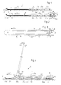
- control board 1 shows a control board 1 and in FIGS. 2 and 3 a driving board 3 of the device according to the invention.
- a connection of control and driving board 1 and 3 to a sliding or rolling scooter or to a rolling vehicle or sliding carriage as the device according to the invention is shown below.
- control and driving boards 1 and 3 are of the same design. Only on one of the boards 1 or 3 is a retractable braking device 4 arranged against the floor 2 .
- the braking device 4 is arranged here on the driving board 3 .
- Each board 1 or 3 here has two guide blades 7a to 7d (the guide blade 7b is not visible in the figures).
- the guide blades 7a and 7b are arranged on the control board 1 and the guide blades 7c and 7d are arranged on the travel board 3 .
- Both boards 1 and 3 have a sliding body 9 and 10 , which here consists, for example, of a carbon-reinforced material.
- the lower sliding surface 11 or 12 of each sliding body 9 or 10 is flat. In its front part in the direction of travel 14 , the control or driving board 1 or 3 is pulled upwards.
- the braking device 4 extends approximately over the entire width of the sliding surface 12 . It has a ground engaging element 13 .
- the engagement element 13 is designed here, for example, as a two-part plate. On one of the plate sides of the one plate 16a , the engaging element 13 is held pivotably in a pivot axis 15 and on the side opposite this side a bar 17 with claw-like elements 19 is formed, which are pressed into the bottom 2 for braking in the direction of the arrow 20 .
- the second plate 16b which is firmly connected to the first plate 16a , serves as an element for whirling up rasped-off floor parts.
- a clearance 21 is arranged upstream of the braking device 4 in the direction of travel 14 .
- the free space cross-section in particular its width b in the direction of travel 14, is selected to be large enough so that when the brakes are rubbed off, ground material can emerge correctly in the direction of the arrow 23 without causing the free space 21 to become blocked.
- the braking effect depends on the extension path of the "plate" 13 .
- the guide blades 7a to 7d are identical. They each consist of one plate each with the contour shown in FIGS. 1 and 2 . (Stainless) steel is the preferred material.
- the top and bottom 25a and 25b are ground as a driving edge according to the desired driving properties.
- Each guide blade 7a to 7d is screwed here to the sides of the sliding body 9 with screws 29 arranged in a line 27a or 27b .
- Line 27a and 27b is off-center to the height h of the guide blades.
- there is a greater or lesser protrusion beyond the relevant sliding surface 11 or 12 It is hereby possible to adapt to the penetration depth, caused by the tightness of the floor material on which gliding is to take place.
- FIGS. 4 to 6 show a device 30 , which can preferably be used to carry people, for locomotion on a floor surface 31 .
- the device according to the invention is designed here, for example, as a “sliding” roller 30 .
- the scooter 30 has a driving board 33 configured analogously to the driving board 3 and a control board 34 configured analogously to the control board 1 .
- the control and travel boards 33 and 34 also have guide blades 35a to 35d designed analogously to the guide blades 7a to 7d .
- the guide blades 35a to 35d are detachably arranged laterally to the supporting sliding surfaces 37a and 37b of the control and driving boards 33 and 34 .
- Driving and control board 33 and 34 are pivotally connected to each other for steering via a swivel joint 36 , on which a steering fork 44 engages.
- a braking device 39 configured analogously to the braking device 4 is also present here.
- the braking device 39 is also pivotable here on a pivot axis 40 and held in the rest position with a tension spring 41 .
- the actuation takes place via a cable 43 , which can be operated by means of a lever 45 arranged on a handlebar fork 44 .
- the material scraped away from the floor 31 during braking is ejected upwards through a space 49 arranged upstream in the direction of travel 47 of the braking device 39 .
- a guide plate 51 is attached to a footboard 50 assigned to the travel board 33 .
- the footboard 50 is firmly connected to the driving board 33 with support elements not explicitly shown here.
- Two foot straps 52a and 52b are arranged on the footboard 50 , into which the feet of a person using the sliding scooter 30 can be inserted. The two feet will be plugged in, especially on a descent gliding on snow, in order to achieve a driving behavior analogous to a surfboard.
- the steering fork 44 is held in the position shown in FIG. 4 by a fixing plate 53 .
- the fixing plate 53 is self-fixing, in particular held in the position shown in FIG. 4 by a spring (not shown here). If the fixing plate 53 is now folded away against its fixing holding force, the control board is pivoted against the steering fork 44 by means of a spring, also not shown. By unlocking the swivel joint 36 , the steering fork 44 can be folded into the position shown in FIG. 6 .
- the folded scooter is now easy to transport.
- the device according to the invention described above is a “sliding” roller 30 .
- This scooter can be transformed into a “rolling” scooter in just a few simple steps.
- wheels 55 which are mounted on a holding plate 57 , are pushed onto the guide blades 7a to 7d or 35a to 35d .
- Each holding plate 57 has upper and lower slots 59a and 59b , in which the guide blades 7a to 7d and 35a to 35d engage.
- the holding plate is now pushed on starting from the front or rear end of the guide blades 7a to 7d or 35a to 35d .
- Each holding plate 57 now has a detent mechanism (not shown) which is provided with a releasable compression spring and which engages over one of the heads of the screws 29 .
- Other detachable locking mechanisms can of course be used.
- the device according to the invention can also be designed as a carriage 63 , which can also be converted into a "soap box-like" vehicle.
- the steerable slide 63 shown in FIGS. 8 and 9 has a left and a right side by side pair, consisting of a driving and a control board 65a , 65b , 66a and 66b , which are analogous to the driving and control boards 1 , 3 , 33 and 34 are formed.
- Guide blades 67a to 67h are also present here.
- Control takes place via a steering fork 69 , which acts via a steering gear (not shown) on a steering rod 70 , which pivots the front control boards 66a or 66b via a steering lever 73a or 73b mounted in a bearing 71a or 71b to change the direction of travel.
- a braking device 74a or 74b is arranged at the rear end of each travel board 65a or 65b .
- the braking devices 74a and 74b can now be designed as described above or as shown in FIGS. 10 (unbraked state) and 11 (braked state).
- there is a two-plate arrangement 75 which can be pivoted against the floor and which is held pivotably by a pivot joint 76 .
- the plate part 77 of the arrangement 75 connected to the swivel joint 76 is connected via a knee joint lever 80 loaded with a tension spring 79 .
- a cable pull 83 which is guided to one of the two handle levers 84a and 84b on the steering fork 69 , now acts on the knee joint 81 .
- the knee joint lever 80 is stretched, as a result of which the braking device 74a or 74b is brought into engagement with the floor 85 .
- a strap 86 is attached to the sled driver and is connected to a securing part 87 shown in FIG .
- the securing part 87 has a base plate 90 provided with a slot 89 , on which a grip element 91 with a recess 92 for a shaft 93 of a handle 94 shown in FIGS. 12 and 13 is arranged.
- a cable 95 is inserted at the shaft end. The cable 95 is connected to the end of a lever of a double lever arrangement 99 loaded with a tension spring 97 .
- the lever 96 is pivotally held at its other lever end by a pivot bearing 100 .
- the second lever 101 of the double lever arrangement 99 engages approximately in the middle of the lever 96 .
- the cable pull 83 penetrates the lever 101 by means of a through hole. Immediately before the through hole, a sheath 102 is firmly connected to the cable 83 . If the braking device 74a or 74b is actuated with the relevant handle lever 84a or 84b , the sheathing 102 arranged on the cable pull 83 moves away from the lever 101 .
- the handle 94 is held in the securing part 87 only by the cable 95 . It is therefore easily swiveled away from the vertical for safety reasons
- the slide 63 has a raised seat 103 and on both sides directly above the attachment of the driving and control boards 65a and 65b and 66a and 66b a footrest 104a and 104b .
- Each footrest 104a and 104b has fields 105c to 105d with a rough covering in order to achieve a good foot sole holder that is secured against slipping.
- the steering rod (tie rod) 70 engages on both sides on a steering lever 73a and 73b , which, as can be seen in particular in FIG. 15 , is connected in a rotationally fixed manner via a bolt 107a or 107b to a control board 66a or 66b .
- the bolts 107a and 107b penetrate with a clearance fit in each case a holding cylinder 109a or 109b , which are each held on the carriage chassis 111 via a flange 109a or 109b .
- the holding cylinders 109a and 109b are made of a plastic with good sliding properties, such as Delrin.
- Each steering lever 73a and 73b is rotatably connected to the respective bolt 107a or 107b by lock nuts 112 .
- each bolt 107a or 107b is rotatably held in a cone 113a and 113b on the top and bottom of the holding cylinder 109a or 109b .
- the respective lower cone 113b sits on a block 114 connected to the control board 66a or 66b .
- each pin 107a or 107b is firmly connected to the respective control board 66a or 66b .
- a swivel joint can also be provided at the connection point between the bolt-block-control board, which permits a swivel movement perpendicular to the longitudinal axis of the control boards 66a and 66b . This results in a better driving behavior of the carriage 63 in uneven terrain.
- the carriage 63 can furthermore have a ski lift bracket attachment device 117 , as is shown schematically in FIG. 8 once in and once out.
- the ski lift bracket mounting device 117 essentially consists of a two-armed lever rod 120 that is pivotable about a horizontal axis 119 .
- One end of the lever rod 120 can be locked with a bolt 121 in such a way that the lever rod 120 is approximately vertical.
- the other lever arm has an end region 122 that is angled backwards.
- the ski lift bracket can be hooked into this end region 122 .
- the ski lift suspension device preferably has two rigidly connected to one another two-armed lever rods, which are at a mutual distance from each other are arranged that the ski lift bracket with its connected to the tow rope Middle element comes to lie between the two lever rods.
- the left and the Right seat brackets then each grip an angled end area of the lever rods on.
- the latch 121 can also be unlocked together with the emergency stop release.
- the guide blades 7a - 7d ; 35a - 35d and 67a - 67h have a row of holes 27a and 27b inserted through the screws 29 to fix the blades on the sides of the sliding bodies of the control and driving boards.
- a row of holes 27a and 27b inserted through the screws 29 to fix the blades on the sides of the sliding bodies of the control and driving boards.
- a screw fastening other types of fastening, such as, for example, latching in, can be used.
Landscapes
- Engineering & Computer Science (AREA)
- Chemical & Material Sciences (AREA)
- Combustion & Propulsion (AREA)
- Transportation (AREA)
- Mechanical Engineering (AREA)
- Motorcycle And Bicycle Frame (AREA)
- Toys (AREA)
- Lighting Device Outwards From Vehicle And Optical Signal (AREA)
- Soil Working Implements (AREA)
- Tires In General (AREA)
- Handcart (AREA)
Applications Claiming Priority (2)
| Application Number | Priority Date | Filing Date | Title |
|---|---|---|---|
| CH175899 | 1999-09-27 | ||
| CH175899 | 1999-09-27 |
Publications (3)
| Publication Number | Publication Date |
|---|---|
| EP1086877A2 true EP1086877A2 (fr) | 2001-03-28 |
| EP1086877A3 EP1086877A3 (fr) | 2001-05-23 |
| EP1086877B1 EP1086877B1 (fr) | 2005-02-23 |
Family
ID=4217887
Family Applications (1)
| Application Number | Title | Priority Date | Filing Date |
|---|---|---|---|
| EP00810896A Expired - Lifetime EP1086877B1 (fr) | 1999-09-27 | 2000-09-27 | Véhicule pour le transport de personnes |
Country Status (3)
| Country | Link |
|---|---|
| EP (1) | EP1086877B1 (fr) |
| AT (1) | ATE289555T1 (fr) |
| DE (1) | DE50009577D1 (fr) |
Cited By (2)
| Publication number | Priority date | Publication date | Assignee | Title |
|---|---|---|---|---|
| US7487974B2 (en) * | 2003-05-16 | 2009-02-10 | Arctic Cat Inc. | Staggered ski skag |
| FR2949742A1 (fr) * | 2009-09-10 | 2011-03-11 | Jean-Claude Chauveau | Dispositif de deplacement par glissement sur le sol |
Citations (4)
| Publication number | Priority date | Publication date | Assignee | Title |
|---|---|---|---|---|
| US2006328A (en) | 1934-07-25 | 1935-06-25 | Albert J Scholtes | Center bowing steering and braking sled runners |
| US3519284A (en) | 1967-09-27 | 1970-07-07 | Ryoji Toki | Sleigh |
| DE3006656A1 (de) | 1980-02-22 | 1981-09-17 | Robert Bosch Gmbh, 7000 Stuttgart | Dichtung |
| CH685616A5 (de) | 1992-03-11 | 1995-08-31 | Lemiteg Lebensmittel Und Freiz | Rodelschlitten mit Kufen. |
Family Cites Families (10)
| Publication number | Priority date | Publication date | Assignee | Title |
|---|---|---|---|---|
| US1394629A (en) * | 1920-02-09 | 1921-10-25 | Jr John Leicht | Sled |
| US2024423A (en) * | 1935-04-27 | 1935-12-17 | Brunetti Louis | Wheel attachment for sleds |
| US2513199A (en) * | 1947-03-18 | 1950-06-27 | Gerhard J Ohlhaver | Scooter |
| DE866614C (de) * | 1950-11-05 | 1953-02-12 | Hermann Wolf | Zusammenlegbarer und in eine Karre umwandelbarer Schlitten |
| US3779572A (en) * | 1971-09-24 | 1973-12-18 | S Cheney | Convertible snow vehicle trailer |
| DE2210784A1 (de) * | 1972-03-07 | 1973-09-13 | Hermann Dr Holzmann | Bremse fuer skibob |
| US3799565A (en) * | 1972-05-23 | 1974-03-26 | W Burtis | Recreation vehicle |
| US4152007A (en) * | 1977-04-22 | 1979-05-01 | Smith Jack E | Ski brake |
| JPH01141171A (ja) * | 1987-11-25 | 1989-06-02 | Sumitomo Rubber Ind Ltd | 雪上車両 |
| US5509683A (en) * | 1995-09-25 | 1996-04-23 | Daniel; Dorce L. | Brake assembly for snow skis and snow boards |
-
2000
- 2000-09-27 AT AT00810896T patent/ATE289555T1/de active
- 2000-09-27 EP EP00810896A patent/EP1086877B1/fr not_active Expired - Lifetime
- 2000-09-27 DE DE50009577T patent/DE50009577D1/de not_active Expired - Lifetime
Patent Citations (4)
| Publication number | Priority date | Publication date | Assignee | Title |
|---|---|---|---|---|
| US2006328A (en) | 1934-07-25 | 1935-06-25 | Albert J Scholtes | Center bowing steering and braking sled runners |
| US3519284A (en) | 1967-09-27 | 1970-07-07 | Ryoji Toki | Sleigh |
| DE3006656A1 (de) | 1980-02-22 | 1981-09-17 | Robert Bosch Gmbh, 7000 Stuttgart | Dichtung |
| CH685616A5 (de) | 1992-03-11 | 1995-08-31 | Lemiteg Lebensmittel Und Freiz | Rodelschlitten mit Kufen. |
Cited By (2)
| Publication number | Priority date | Publication date | Assignee | Title |
|---|---|---|---|---|
| US7487974B2 (en) * | 2003-05-16 | 2009-02-10 | Arctic Cat Inc. | Staggered ski skag |
| FR2949742A1 (fr) * | 2009-09-10 | 2011-03-11 | Jean-Claude Chauveau | Dispositif de deplacement par glissement sur le sol |
Also Published As
| Publication number | Publication date |
|---|---|
| DE50009577D1 (de) | 2005-03-31 |
| EP1086877B1 (fr) | 2005-02-23 |
| EP1086877A3 (fr) | 2001-05-23 |
| ATE289555T1 (de) | 2005-03-15 |
Similar Documents
| Publication | Publication Date | Title |
|---|---|---|
| CH683170A5 (de) | Schreitfahrzeug. | |
| DE2628242A1 (de) | Verbesserung fuer schlitten oder schlittenaehnliche fahrzeuge | |
| DE102012021613A1 (de) | Schwerlast-Transportfahrzeug zum Transport eines länglichen Objekts | |
| DE2107852A1 (de) | Zusammenlegbarer Skibob | |
| EP0564687B1 (fr) | Dispositif de remorquage | |
| DE3133636A1 (de) | Rangieranordnung an einem rollstuhl | |
| EP1086877B1 (fr) | Véhicule pour le transport de personnes | |
| EP1448073A1 (fr) | Dispositif de transport pour bagages ou analogues | |
| DE4223114C2 (de) | Sportgerät | |
| DE19546748A1 (de) | Rolltreppengängiger Transportwagen | |
| DE102011010909A1 (de) | Bewegliche Beinablagen zum Auf- und Abständern oder zur Sitzabsenkung eines kurvenneigbaren Zwei- oder Dreirades | |
| DE2622246C2 (de) | Maschine zum Verteilen von streubarem Material | |
| DE102007058434B3 (de) | Adapter zur Umrüstung eines Fahrgerätes für eine Krankentrage, Bahre oder einen Sarg für den Transport des Sarges und Fahrgerät mit einem derartigen Adapter | |
| DE102005039209B3 (de) | Lastkarren | |
| DE102012214930A1 (de) | Fahrzeug | |
| AT501968B1 (de) | Mitführhilfe | |
| EP3437704B1 (fr) | Patin à roulettes avec chassis en forme de boîte | |
| DE4004528A1 (de) | Bindungseinrichtung fuer einen langlaufskischuh | |
| DE2015120C3 (de) | Schlitten für Lasttransport, insbesondere zum Abtransport von Sammelgut aus Weinbergen od.dgl | |
| DE8206828U1 (de) | Geraet fuer die benutzung als ski-schlitten" | |
| DE247613C (fr) | ||
| DE3605231A1 (de) | Gleitvorrichtung fuer kinderwagen und vergleichbare radfahrzeuge | |
| AT9212U1 (de) | Schlitten mit bremseinrichtung | |
| DE202009008952U1 (de) | Sportrodel | |
| DE4133569A1 (de) | Spiel- und sportgeraet |
Legal Events
| Date | Code | Title | Description |
|---|---|---|---|
| PUAI | Public reference made under article 153(3) epc to a published international application that has entered the european phase |
Free format text: ORIGINAL CODE: 0009012 |
|
| AK | Designated contracting states |
Kind code of ref document: A2 Designated state(s): AT CH DE FR IT LI |
|
| AX | Request for extension of the european patent |
Free format text: AL;LT;LV;MK;RO;SI |
|
| PUAL | Search report despatched |
Free format text: ORIGINAL CODE: 0009013 |
|
| AK | Designated contracting states |
Kind code of ref document: A3 Designated state(s): AT BE CH CY DE DK ES FI FR GB GR IE IT LI LU MC NL PT SE |
|
| AX | Request for extension of the european patent |
Free format text: AL;LT;LV;MK;RO;SI |
|
| 17P | Request for examination filed |
Effective date: 20011004 |
|
| AKX | Designation fees paid |
Free format text: AT CH DE FR IT LI |
|
| 17Q | First examination report despatched |
Effective date: 20040227 |
|
| GRAP | Despatch of communication of intention to grant a patent |
Free format text: ORIGINAL CODE: EPIDOSNIGR1 |
|
| RTI1 | Title (correction) |
Free format text: VEHICLE ADAPTED FOR TRANSPORTING PEOPLE |
|
| GRAS | Grant fee paid |
Free format text: ORIGINAL CODE: EPIDOSNIGR3 |
|
| GRAA | (expected) grant |
Free format text: ORIGINAL CODE: 0009210 |
|
| AK | Designated contracting states |
Kind code of ref document: B1 Designated state(s): AT CH DE FR IT LI |
|
| REG | Reference to a national code |
Ref country code: CH Ref legal event code: EP |
|
| REG | Reference to a national code |
Ref country code: CH Ref legal event code: NV Representative=s name: KELLER & PARTNER PATENTANWAELTE AG |
|
| REF | Corresponds to: |
Ref document number: 50009577 Country of ref document: DE Date of ref document: 20050331 Kind code of ref document: P |
|
| PLBE | No opposition filed within time limit |
Free format text: ORIGINAL CODE: 0009261 |
|
| STAA | Information on the status of an ep patent application or granted ep patent |
Free format text: STATUS: NO OPPOSITION FILED WITHIN TIME LIMIT |
|
| 26N | No opposition filed |
Effective date: 20051124 |
|
| ET | Fr: translation filed | ||
| PG25 | Lapsed in a contracting state [announced via postgrant information from national office to epo] |
Ref country code: IT Free format text: LAPSE BECAUSE OF NON-PAYMENT OF DUE FEES Effective date: 20070927 |
|
| PGFP | Annual fee paid to national office [announced via postgrant information from national office to epo] |
Ref country code: DE Payment date: 20090929 Year of fee payment: 10 |
|
| REG | Reference to a national code |
Ref country code: FR Ref legal event code: ST Effective date: 20110531 |
|
| REG | Reference to a national code |
Ref country code: DE Ref legal event code: R119 Ref document number: 50009577 Country of ref document: DE Effective date: 20110401 |
|
| PG25 | Lapsed in a contracting state [announced via postgrant information from national office to epo] |
Ref country code: FR Free format text: LAPSE BECAUSE OF NON-PAYMENT OF DUE FEES Effective date: 20100930 Ref country code: DE Free format text: LAPSE BECAUSE OF NON-PAYMENT OF DUE FEES Effective date: 20110401 |
|
| PGFP | Annual fee paid to national office [announced via postgrant information from national office to epo] |
Ref country code: IT Payment date: 20090928 Year of fee payment: 10 |
|
| PGRI | Patent reinstated in contracting state [announced from national office to epo] |
Ref country code: IT Effective date: 20110616 |
|
| PGFP | Annual fee paid to national office [announced via postgrant information from national office to epo] |
Ref country code: FR Payment date: 20090908 Year of fee payment: 10 |
|
| PGFP | Annual fee paid to national office [announced via postgrant information from national office to epo] |
Ref country code: AT Payment date: 20130926 Year of fee payment: 14 Ref country code: CH Payment date: 20130821 Year of fee payment: 14 |
|
| PGRI | Patent reinstated in contracting state [announced from national office to epo] |
Ref country code: IT Effective date: 20110616 |
|
| REG | Reference to a national code |
Ref country code: CH Ref legal event code: PL |
|
| REG | Reference to a national code |
Ref country code: AT Ref legal event code: MM01 Ref document number: 289555 Country of ref document: AT Kind code of ref document: T Effective date: 20140927 |
|
| PG25 | Lapsed in a contracting state [announced via postgrant information from national office to epo] |
Ref country code: CH Free format text: LAPSE BECAUSE OF NON-PAYMENT OF DUE FEES Effective date: 20140930 Ref country code: LI Free format text: LAPSE BECAUSE OF NON-PAYMENT OF DUE FEES Effective date: 20140930 |
|
| PG25 | Lapsed in a contracting state [announced via postgrant information from national office to epo] |
Ref country code: AT Free format text: LAPSE BECAUSE OF NON-PAYMENT OF DUE FEES Effective date: 20140927 |