EP1086889A2 - Stabilisationsflosse - Google Patents
Stabilisationsflosse Download PDFInfo
- Publication number
- EP1086889A2 EP1086889A2 EP00120138A EP00120138A EP1086889A2 EP 1086889 A2 EP1086889 A2 EP 1086889A2 EP 00120138 A EP00120138 A EP 00120138A EP 00120138 A EP00120138 A EP 00120138A EP 1086889 A2 EP1086889 A2 EP 1086889A2
- Authority
- EP
- European Patent Office
- Prior art keywords
- fin
- plane
- wedges
- vertex
- transverse central
- Prior art date
- Legal status (The legal status is an assumption and is not a legal conclusion. Google has not performed a legal analysis and makes no representation as to the accuracy of the status listed.)
- Withdrawn
Links
- 239000003381 stabilizer Substances 0.000 title claims abstract description 14
- 241001212149 Cathetus Species 0.000 claims description 4
- 230000007423 decrease Effects 0.000 description 3
- 238000004519 manufacturing process Methods 0.000 description 3
- 238000000926 separation method Methods 0.000 description 3
- 238000005259 measurement Methods 0.000 description 2
- 230000004048 modification Effects 0.000 description 2
- 238000012986 modification Methods 0.000 description 2
- 230000006641 stabilisation Effects 0.000 description 2
- 238000011105 stabilization Methods 0.000 description 2
- UJCHIZDEQZMODR-BYPYZUCNSA-N (2r)-2-acetamido-3-sulfanylpropanamide Chemical compound CC(=O)N[C@@H](CS)C(N)=O UJCHIZDEQZMODR-BYPYZUCNSA-N 0.000 description 1
- 241001669680 Dormitator maculatus Species 0.000 description 1
- 238000013459 approach Methods 0.000 description 1
- 230000009286 beneficial effect Effects 0.000 description 1
- 230000015556 catabolic process Effects 0.000 description 1
- 238000006731 degradation reaction Methods 0.000 description 1
- 230000000670 limiting effect Effects 0.000 description 1
- 239000000463 material Substances 0.000 description 1
- 238000011144 upstream manufacturing Methods 0.000 description 1
Images



Classifications
-
- B—PERFORMING OPERATIONS; TRANSPORTING
- B63—SHIPS OR OTHER WATERBORNE VESSELS; RELATED EQUIPMENT
- B63B—SHIPS OR OTHER WATERBORNE VESSELS; EQUIPMENT FOR SHIPPING
- B63B1/00—Hydrodynamic or hydrostatic features of hulls or of hydrofoils
- B63B1/16—Hydrodynamic or hydrostatic features of hulls or of hydrofoils deriving additional lift from hydrodynamic forces
- B63B1/24—Hydrodynamic or hydrostatic features of hulls or of hydrofoils deriving additional lift from hydrodynamic forces of hydrofoil type
- B63B1/248—Shape, hydrodynamic features, construction of the foil
-
- B—PERFORMING OPERATIONS; TRANSPORTING
- B63—SHIPS OR OTHER WATERBORNE VESSELS; RELATED EQUIPMENT
- B63H—MARINE PROPULSION OR STEERING
- B63H25/00—Steering; Slowing-down otherwise than by use of propulsive elements; Dynamic anchoring, i.e. positioning vessels by means of main or auxiliary propulsive elements
- B63H25/06—Steering by rudders
- B63H25/38—Rudders
Definitions
- the present invention relates to a stabilizer fin, particularly for water-borne crafts.
- EP-0,571,401 discloses a hydrodynamic stabilizer fin, to be used in a submerged condition, which is constituted by a single element having an elongated body at the rear (pointed) end of which there is an element having a substantially wedge-shaped transverse cross-section and in which the vertex is blended with said rear end and the end is flat.
- a drawback of the conventional stabilizer fin is that it can be subject to vibration and also produces noise.
- vorticity-promoting devices which are constituted by elements protruding from the wing and that can be likened to rectangular mini-ailerons which have alternating inclinations with respect to the surface of the wing and are supported by small cylinders.
- the aim of the present invention is to solve the above noted problems, eliminating the drawbacks of the cited prior art, by providing a stabilizer fin, particularly for water-borne crafts, which allows to increase lift and reduce vibrations and noise.
- an object of the present invention is to provide a fin which is structurally simple and easy to manufacture.
- Another object is to provide a fin which also allows to achieve an improvement in terms of maximum obtainable lift.
- Another important object is to provide a stabilizer fin which has low manufacturing costs and can be manufactured with conventional machines and equipment.
- Another object is to provide a solution which can also be applied in conventional fins by virtue of interventions which have very low costs, so as to allow to increase their roll stabilization effectiveness.
- a stabilizer fin particularly for water-borne crafts, which comprises a tapering body with a symmetrical profile, characterized in that one or more wedge- or ramp-shaped elements are provided on the lateral surface or surfaces of the body and protrude therefrom.
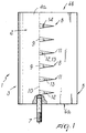
- 1 designates a stabilizer fin which is particularly used in water-borne crafts mainly in order to increase their lift.
- the fin comprises a body, designated by the reference numeral 2, which has a tapering shape with a symmetrical cross-section, for example of type known in the literature by the name NACA.
- the body 2 has a first rounded end 3 which protrudes so as to form a pair of first lateral surfaces 4a and 4b which are blended one another at a second pointed end 5.
- the body 2 is transversely provided with two second flat lateral surfaces 6a and 6b, and a shaft 7 for connection, for example, to the keel of a water-borne craft is associated with at least one of such surfaces.
- the stabilizer fin is characterized in that it has, at one or both of the first lateral surfaces 4a and 4b, one or more wedge- or ramp-shaped elements, designated by the reference numeral 8.
- the wedges or ramps 8 have an essentially triangular plan shape, in which the base 9 lies approximately at a transverse central plane 10 of the body 2 and the vertex 11 is directed toward the second pointed end 5.
- Each wedge or ramp 8 further has, in a sectional view taken along a plane 12 that passes through an altitude line that connects each base 9 to the vertex 11 and is perpendicular to a transverse central plane of the body 2, a triangular configuration in which one cathetus 13 lies at a plane which is tangent to the intersection of the planes 12 and 10.
- the cathetus 13 is part of the upper surface 14 of each wedge or ramp, while the vertex 11 thereof is spaced by a given extent from the adjacent first lateral surface of the body 2.
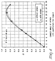
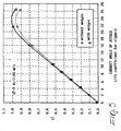
- Figures 4 to 9 are charts related to measurements taken on a specimen executed according to the teachings of the present invention and conducted in a cavitation tunnel.
- ⁇ designates the cavitation index
- C L designates the lift coefficient
- ⁇ designates the angle of attack.
- Figures 4 and 5 are charts in which the X-axis plots the angle of attack and the Y-axis plots the lift coefficient with a cavitation index of 2 and 3 and considering a test section velocity, designated by V C , equal to approximately 7 m/s, which corresponds to a Reynolds number (Rn) of 1.7x10 6 .
- a circle (o) designates the values that can be obtained from a fin without the wedges or ramps and a triangle ( ⁇ ) designates the values that can be found with the solution according to the present invention.
- laminar cavitation at the leading edge causes separation of the boundary layer ahead of the wedge, gradually canceling out its beneficial effects.
- Figures 6 and 7 plot the drag coefficient, designated as C D , considering a cavitation index ⁇ of 3 and 2 respectively.
- the boundary layer between two adjacent wedges or ramps becomes thinner and part of the boundary layer that had formed upstream along the cord is expelled in the external flow of the wedge or ramp.
- Figures 8 and 9 plot these ratios and therefore plot the trends of the efficiency of the fin as the angle of attack varies.
- the illustrated solution can be easily manufactured and obtained even on conventional fins, since the modification can be achieved rapidly and easily.
- the materials and the shapes that constitute the wedges or ramps, as well as their number, arrangement and spacing, can be the most pertinent according to specific requirements.
Landscapes
- Physics & Mathematics (AREA)
- Fluid Mechanics (AREA)
- Chemical & Material Sciences (AREA)
- Engineering & Computer Science (AREA)
- Combustion & Propulsion (AREA)
- Mechanical Engineering (AREA)
- Ocean & Marine Engineering (AREA)
- Electroluminescent Light Sources (AREA)
- Other Liquid Machine Or Engine Such As Wave Power Use (AREA)
- Non-Silver Salt Photosensitive Materials And Non-Silver Salt Photography (AREA)
- Moulds, Cores, Or Mandrels (AREA)
- Polishing Bodies And Polishing Tools (AREA)
Applications Claiming Priority (2)
| Application Number | Priority Date | Filing Date | Title |
|---|---|---|---|
| IT1999TV000102A IT1311861B1 (it) | 1999-09-22 | 1999-09-22 | Struttura di pinna stabilizzatrice |
| ITTV990102 | 1999-09-22 |
Publications (2)
| Publication Number | Publication Date |
|---|---|
| EP1086889A2 true EP1086889A2 (de) | 2001-03-28 |
| EP1086889A3 EP1086889A3 (de) | 2002-05-29 |
Family
ID=11420680
Family Applications (1)
| Application Number | Title | Priority Date | Filing Date |
|---|---|---|---|
| EP00120138A Withdrawn EP1086889A3 (de) | 1999-09-22 | 2000-09-20 | Stabilisationsflosse |
Country Status (2)
| Country | Link |
|---|---|
| EP (1) | EP1086889A3 (de) |
| IT (1) | IT1311861B1 (de) |
Cited By (3)
| Publication number | Priority date | Publication date | Assignee | Title |
|---|---|---|---|---|
| CN102975839A (zh) * | 2012-12-20 | 2013-03-20 | 刘文斌 | 一种波浪能推进装置及安装该装置的水上交通工具 |
| CN121425443A (zh) * | 2025-11-03 | 2026-01-30 | 中国科学院声学研究所 | 一种减阻翼型吊环和宽速域auv |
| CN121425443B (zh) * | 2025-11-03 | 2026-05-08 | 中国科学院声学研究所 | 一种减阻翼型吊环和宽速域auv |
Families Citing this family (1)
| Publication number | Priority date | Publication date | Assignee | Title |
|---|---|---|---|---|
| CN111332420B (zh) * | 2018-12-18 | 2022-04-15 | 英辉南方造船(广州番禺)有限公司 | 一种高速单体船航向稳定鳍及其安装方法 |
Citations (1)
| Publication number | Priority date | Publication date | Assignee | Title |
|---|---|---|---|---|
| EP0571401A1 (de) | 1991-01-04 | 1993-12-01 | Vickers Plc | Hydrodynamische flosse für wasserfahrzeuge. |
Family Cites Families (6)
| Publication number | Priority date | Publication date | Assignee | Title |
|---|---|---|---|---|
| US2099229A (en) * | 1936-01-15 | 1937-11-16 | Possenheim Louis | Fin equipped rudder |
| US2800291A (en) * | 1950-10-24 | 1957-07-23 | Stephens Arthur Veryan | Solid boundary surface for contact with a relatively moving fluid medium |
| US5386955A (en) * | 1986-05-22 | 1995-02-07 | Rolls-Royce Plc | Control of fluid flow |
| US4930729A (en) * | 1986-05-22 | 1990-06-05 | Rolls-Royce Plc | Control of fluid flow |
| US4825795A (en) * | 1987-03-19 | 1989-05-02 | Slemmons Arthur J | Sailing craft keel and rudder flow modifiers |
| IL115768A0 (en) * | 1995-10-25 | 1996-01-19 | Steinberg Gal | Propeller foil |
-
1999
- 1999-09-22 IT IT1999TV000102A patent/IT1311861B1/it active
-
2000
- 2000-09-20 EP EP00120138A patent/EP1086889A3/de not_active Withdrawn
Patent Citations (1)
| Publication number | Priority date | Publication date | Assignee | Title |
|---|---|---|---|---|
| EP0571401A1 (de) | 1991-01-04 | 1993-12-01 | Vickers Plc | Hydrodynamische flosse für wasserfahrzeuge. |
Cited By (3)
| Publication number | Priority date | Publication date | Assignee | Title |
|---|---|---|---|---|
| CN102975839A (zh) * | 2012-12-20 | 2013-03-20 | 刘文斌 | 一种波浪能推进装置及安装该装置的水上交通工具 |
| CN121425443A (zh) * | 2025-11-03 | 2026-01-30 | 中国科学院声学研究所 | 一种减阻翼型吊环和宽速域auv |
| CN121425443B (zh) * | 2025-11-03 | 2026-05-08 | 中国科学院声学研究所 | 一种减阻翼型吊环和宽速域auv |
Also Published As
| Publication number | Publication date |
|---|---|
| ITTV990102A1 (it) | 2001-03-22 |
| EP1086889A3 (de) | 2002-05-29 |
| IT1311861B1 (it) | 2002-03-19 |
Similar Documents
| Publication | Publication Date | Title |
|---|---|---|
| US6345791B1 (en) | Streamwise variable height riblets for reducing skin friction drag of surfaces | |
| JP5823667B2 (ja) | 特に航空機の翼のための翼端形状 | |
| US6431498B1 (en) | Scalloped wing leading edge | |
| US8366178B2 (en) | Vehicle and vehicle substructure | |
| CA2788210C (en) | Aircraft tail surface with a leading edge section of undulated shape | |
| RU2499732C2 (ru) | Аэродинамическая конструкция с неравномерно расположенными выступами для отклонения скачка уплотнения | |
| US20010030264A1 (en) | Method and apparatus for reducing trailing vortices in the wake of an aircraft | |
| WO1987001345A1 (en) | Foil | |
| JP4653831B2 (ja) | 空気入りタイヤ | |
| DE69504560T2 (de) | Schiffsrumpfform | |
| JP6563645B2 (ja) | 気流遮断デバイス | |
| US4409922A (en) | V-Shaped bottom for speedy motorboats having improved planing supporting skids | |
| US6606959B1 (en) | High speed drag reducing ventilation for marine vessel hulls | |
| KR20140003361A (ko) | 수상선박용 수중익 | |
| KR950010360B1 (ko) | 와이퍼블레이드 | |
| JP5240458B2 (ja) | 航空機用翼 | |
| US20160288632A1 (en) | Vehicle sunroof wind deflector | |
| EP1086889A2 (de) | Stabilisationsflosse | |
| EP2247497B1 (de) | Aerodynamische struktur mit asymmetrischem stossdämpfer | |
| US4660788A (en) | Supercritical wing | |
| JPH0310913A (ja) | 空気入りタイヤ | |
| GB2136739A (en) | A fin, rudder or keel | |
| US4913381A (en) | Aerodynamic components having leading edge devices | |
| JPH09136693A (ja) | 船舶用ビルジ渦エネルギー回収装置 | |
| CN217227900U (zh) | 一种螺旋桨和飞行器 |
Legal Events
| Date | Code | Title | Description |
|---|---|---|---|
| PUAI | Public reference made under article 153(3) epc to a published international application that has entered the european phase |
Free format text: ORIGINAL CODE: 0009012 |
|
| AK | Designated contracting states |
Kind code of ref document: A2 Designated state(s): AT BE CH CY DE DK ES FI FR GB GR IE IT LI LU MC NL PT SE |
|
| AX | Request for extension of the european patent |
Free format text: AL;LT;LV;MK;RO;SI |
|
| PUAL | Search report despatched |
Free format text: ORIGINAL CODE: 0009013 |
|
| AK | Designated contracting states |
Kind code of ref document: A3 Designated state(s): AT BE CH CY DE DK ES FI FR GB GR IE IT LI LU MC NL PT SE |
|
| AX | Request for extension of the european patent |
Free format text: AL;LT;LV;MK;RO;SI |
|
| RIC1 | Information provided on ipc code assigned before grant |
Free format text: 7B 63B 1/24 A, 7B 63B 39/06 B |
|
| 17P | Request for examination filed |
Effective date: 20021031 |
|
| AKX | Designation fees paid |
Designated state(s): AT BE CH CY DE DK ES FI FR GB GR IE IT LI LU MC NL PT SE |
|
| 17Q | First examination report despatched |
Effective date: 20030514 |
|
| STAA | Information on the status of an ep patent application or granted ep patent |
Free format text: STATUS: THE APPLICATION HAS BEEN WITHDRAWN |
|
| 18W | Application withdrawn |
Effective date: 20030918 |