EP1086923B1 - Vorrichtung zum Öffnen und Schliessen von Aufzugstürflügeln - Google Patents
Vorrichtung zum Öffnen und Schliessen von Aufzugstürflügeln Download PDFInfo
- Publication number
- EP1086923B1 EP1086923B1 EP00203327A EP00203327A EP1086923B1 EP 1086923 B1 EP1086923 B1 EP 1086923B1 EP 00203327 A EP00203327 A EP 00203327A EP 00203327 A EP00203327 A EP 00203327A EP 1086923 B1 EP1086923 B1 EP 1086923B1
- Authority
- EP
- European Patent Office
- Prior art keywords
- shutters
- opening
- coupling
- closing
- floor
- Prior art date
- Legal status (The legal status is an assumption and is not a legal conclusion. Google has not performed a legal analysis and makes no representation as to the accuracy of the status listed.)
- Expired - Lifetime
Links
- 230000008878 coupling Effects 0.000 claims abstract description 44
- 238000010168 coupling process Methods 0.000 claims abstract description 44
- 238000005859 coupling reaction Methods 0.000 claims abstract description 44
- 230000033001 locomotion Effects 0.000 claims abstract description 25
- 230000010355 oscillation Effects 0.000 description 4
- 230000009471 action Effects 0.000 description 3
- 230000008901 benefit Effects 0.000 description 3
- 238000012423 maintenance Methods 0.000 description 3
- 238000010276 construction Methods 0.000 description 2
- 230000007935 neutral effect Effects 0.000 description 2
- 230000001105 regulatory effect Effects 0.000 description 2
- 230000001133 acceleration Effects 0.000 description 1
- 230000006978 adaptation Effects 0.000 description 1
- 238000007792 addition Methods 0.000 description 1
- 230000005540 biological transmission Effects 0.000 description 1
- 238000009434 installation Methods 0.000 description 1
- 230000010354 integration Effects 0.000 description 1
- 230000007246 mechanism Effects 0.000 description 1
- 238000000034 method Methods 0.000 description 1
- 238000012986 modification Methods 0.000 description 1
- 230000004048 modification Effects 0.000 description 1
- 230000009467 reduction Effects 0.000 description 1
- 239000011435 rock Substances 0.000 description 1
- 238000006467 substitution reaction Methods 0.000 description 1
Images


Classifications
-
- B—PERFORMING OPERATIONS; TRANSPORTING
- B66—HOISTING; LIFTING; HAULING
- B66B—ELEVATORS; ESCALATORS OR MOVING WALKWAYS
- B66B13/00—Doors, gates, or other apparatus controlling access to, or exit from, cages or lift well landings
- B66B13/02—Door or gate operation
- B66B13/12—Arrangements for effecting simultaneous opening or closing of cage and landing doors
Definitions
- the present invention relates to a device for opening and closing lift door shutters.
- the opening and closing operation of the lift door shutters is a critical point in the lift operation. Indeed the devices actuating these functions must be not only reliable and safe, but must also be adapted to allow the whole lift system to operate under precise rules concerning the various operative parameters.
- Lifts are generally provided with central opening doors with two, four or six shutters or side opening doors with one, two or three shutters, while the known opening and closing devices for these shutters consist of rocking arms or belts. Although such devices solve said technical problem, nevertheless they have some drawbacks.
- the rocking arm devices have the advantageous feature of a particular mechanical structure with a motion similar to an electronic control, but are not suitable to actuate shutters with different opening and closing times, as it may be required by operative needs assigning a maximum time between start of deceleration and end of acceleration of the car in transit at a determined floor of the building, as well as a maximum speed of shutter closure to be strictly respected for safety reasons. This happens because the rocking arm devices are designed with a sinusoidal speed cycle that is always equal both in the opening and closing phase.
- the known belt devices are adapted to be operated with different door opening and closing speeds, but are provided with complex linkages to actuate one of the main components of the known devices, hereinafter referred to as retractable coupling, and of the corresponding shutters.
- belts are generally provided at their lacing point with a mechanical member which drives through a plurality of linkages said retractable coupling and counsequently opening and closing of the shutters.
- This belt device has also problems of maintenance and reliability of the belt, as said belt often works under twist with reduction of its average life.
- Another drawback of the known belt devices consists of the mismatching of the various linkages with consequent plays and a corresponding movement of the shutters with oscillations making the whole device not entirely reliable.
- US 5,246,089 discloses a door drive apparatus with locking mechanism for elevator doors comprising a latch device for coupling floor door shutters during closed and open settings.
- Actuation system is provided by enclosing a drive motor and a transmission unit commonly used for this class of application, whilst the opening and closing elevator door motion is controlled by a cam-based system such that a smooth starting and braking trend can be performed.
- Disadvantages of the above-mentioned apparatus are the same discussed in the previous part of the present description.
- the belt indeed, is constrained during its motion to a torsion angle at connection with the clamping element causing repeated maintenance operations due to the consequent fast wear of the same belt.
- the object of the present invention is to remove the above mentioned drawbacks of the state of the art devices.
- the device for opening and closing lift door shutters of the invention comprises support means operatively associated to the car shutters, means for locking and unlocking the latch and coupling the floor shutters, moving means operatively connected to said support means, and at least one belt, where said belt directly drives mechanical means operatively associated with said means for locking and unlocking the latch and coupling the floor shutters so as to allow the simultaneous opening and closing movement of both the car shutters and floor shutters.
- the device for opening and closing lift door shutters according to the invention is characterized by the features recited in Claim 1.
- the belt is not twisted in operation and its average life is increased because said belt is a toothed belt and said mechanical means comprise a coupling driving sector consisting of a plate provided at one end with a sector gear adapted to mesh with said toothed belt.
- Another advantage consists in obtaining a micrometric regulation of the neutral point of said means for locking and unlocking the latch and coupling the floor shutters because said coupling driving sector has a plurality of inner seats adapted to lodge a chain and means for its micrometric regulation, said micrometric regulation means comprising a rack travelling on a rod while keeping contact with said chain which is connected to said means for locking and unlocking the latch and coupling the floor shutters.
- a further advantage consists of the possibility to close the latch of the floor shutters in a smooth and silent way because the coupling driving sector has a pin on its vertical symmetry axis, said pin being positioned between said toothed sector and the opposite end of said coupling driving sector with a positioning length proportion of about 2:1.
- the device according to the invention advantageously avoids the presence of plays and oscillations, allowing that the car shutters are perfectly actuated by the moving means because said coupling driving sector has two holes arranged symmetrically in respect of its vertical symmetry axis, is connected to a plate so as to be able to rock around its vertical axis between two end positions by means of said pin and there is a lock unit comprising a rod pivoted on said plate, said rod having a protrusion at one end and a frustoconical member at the other end, adapted to be coupled with one of said holes, said lock unit being also provided with a shoulder on a plate fixed to said support means of the device, near one side end of said support means, said shoulder being adapted to cooperate with said protrusion.
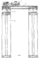
- the device 1 for opening and closing lift door shutters comprises support means on a lift car that will be referred to hereinafter as operator 2.
- Operator 2 generally consists of a frame on which a motor unit 3 is fixed, comprising an electric motor of any known type and not shown in the drawings, associated with a plurality of motion elements allowing to drive a toothed belt 5 which is kept positioned between two gear wheels, the one fixed to the motor unit 3 and the other to a plate arranged at the other longitudinal end of operator 2.
- An electronic control of known type (not shown) is associated to the motor unit 3 for regulating the speed of belt 4 in the stages of opening and closing the door shutters.
- the toothed belt 4 is also coupled to mechanical means fixed on a plate 6 that slides in respect of operator 2, by its fastening to a support 21 movable in respect of operators 2 as it will be better explained hereinafter.
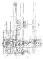
- Said mechanical means generally comprise a coupling driving sector 5 mainly consisting of a plate provided at one end with a toothed sector adapted to be coupled to said belt 4, a plurality of inner seats for containing a chain 7 and means for its micrometric adjustment, two holes 18 symmetrically arranged in respect of its vertical symmetry axis and a rocking pin 23 arranged on said symmetry axis.
- a coupling driving sector 5 mainly consisting of a plate provided at one end with a toothed sector adapted to be coupled to said belt 4, a plurality of inner seats for containing a chain 7 and means for its micrometric adjustment, two holes 18 symmetrically arranged in respect of its vertical symmetry axis and a rocking pin 23 arranged on said symmetry axis.
- said pin 23 is preferably, but not necessarily positioned with a length proportion 2:1 between said toothed sector and the opposite end of the coupling driving sector 5.
- Said adjustment means mainly consist of a rack 13 sliding on a rod 14, the position of said adjustment means being regulated by nuts or equivalent means, said rack 13 being in contact with said chain 7 so as to carry out a micrometric adjustment of the chain, through its movements on the rod 14.
- Said chain 7 is fixed at one end to said coupling driving sector 5 and is connected at the other end to a retractile coupling 8 normally used in the lift construction technique for locking and unlocking the latch of the shutters of the floor doors and for coupling these shutters to the car shutters during the opening and closing operations.
- the retractile coupling 8 is also fixed to a support plate 9 constrained to support 21 to which also plate 6 is constrained, and can slide together with the coupling driving sector 5.
- the retractile coupling 8 formed by a couple of sides 10 having at their ends rectilinear lengths bent toward the opposite side. Sides 10 are connected to one another by a couple of motion elements 11, of which one is driven by said chain 7 through a little gear wheel 22, while a return spring 12 is obliquely arranged between said sides 10 approximately at the central zone of the retractile coupling 8. In this way an adjustment of rack 13 is trasmitted to said motion elements 11 by the chain 7 so as to obtain a perfect adjustment of the neutral point of said retractile coupling 8.
- the coupling driving sector 5 is pivoted on said plate 6 by said pin 23 so as to be able to swing in respect of its vertical axis. Such a swinging motion brings sector 5 to two positions corresponding to an opening and closing action of the retractile coupling 8 as it will better explained hereinafter.
- a lock unit for said sector 5 is assembled on plate 6 at the side opposite to the coupling driving sector 5. More particularly said lock unit comprises a rod 15 constituted by a plurality of rectilinear segments connected to one another, said rod 15 being pivoted near its central part so as to swing in respect of plate 6 in direction of sector 5 and in the opposite direction.
- a protrusion 17 e.g. consisting of a bolt and nut group, while at the opposite end there is a frustoconical member adapted to cooperate with one of the holes 18 made in sector 5.
- a shoulder 19 being part of said lock unit but mounted on a plate fixed to operator 2 near one of its side ends, can cooperate with the protrusion 17, when the motion of plate 6 through belt 4 will bring these two elements 19 and 17 in mutual contact.
- Car shutters 20 are placed below the plate 9 on supports 21 sliding in respect of operator 2, one support being fixed to the group plate 6-plate 9 while the other support is connected to the first support by motion elements of known type, so that the car shutters 20 are connected to the motion of belt 4.
- the door shutters of each floor are provided with a latch adapted to be actuated by the retractable coupling 8 to allow the locking or unlocking action of said shutters and their motion driven by the contemporaneous movement of the car shutters 20.
- device 1 The operation of device 1 is carried out according to the controls given to the lift in the following manner.
- the electronic control actuates the motor and the motion is trasmitted to the toothed belt 4 connected thereto.
- Belt 4 drives the coupling driving sector 5 causing it to oscillate so as to actuate through chain 7 the retractile coupling 8 which grasps the latch of the floor door shutters, unlocks the latch and couples the floor shutters to the car shutters 20 constrained by the supports 21 to belt 4 as hereinbefore described.
- the inclined position of sector 5 due to said oscillation is constrained by the engagement of the frustoconical member 16 with hole 18 of said sector 5, because the movement of belt 4 caused the protrusion 17 to descend shoulder 19 and the consequent locking movement of said frustoconical member 17. In this way plays that could be existing are removed and the shutter do not oscillate mutually being perfectly controlled by the electronic control.
- the electronic control actuates in the opposite way the toothed belt 4 through the electric motor, starting with closure of the car shutters 20 and floor shutters that were mutually constrained in view of the action of the retractile coupling 8.
- protrusion 17 starts to ascend shoulder 19 and consequently the frustoconical member 16 does no more stop oscillation of sector 5 that swings in the opposite direction to its original position acting on the retractable coupling 8 disengaging the floor shutters by releasing their latch which returns to the closing position.
- pin 23 of the coupling driving sector 5 causes it to oscillate so as to allow to reduce the closure speed of the retractable coupling 8 to half of the translation speed of the toothed belt 4, so as to close the latch of the floor shutters in a smooth and noiseless way.
Landscapes
- Elevator Door Apparatuses (AREA)
- Power-Operated Mechanisms For Wings (AREA)
- Vehicle Step Arrangements And Article Storage (AREA)
- Extensible Doors And Revolving Doors (AREA)
- Types And Forms Of Lifts (AREA)
- Operating, Guiding And Securing Of Roll- Type Closing Members (AREA)
Claims (9)
- Eine Vorrichtung zum Öffnen und Schließen von Lifttürflügeln mit Haltemitteln, die operativ Kabinentüren (20) zugeordnet sind, Verriegelungs- und Entriegelungsmitteln für einen Kopplungsriegel (8) und Kopplungsmitteln für die Etagentürflügel, Bewegungsmitteln, die operativ mit den Haltemitteln und wenigstens einem Zahnriemen (4) verbunden sind, wobei der Zahnriemen (4) mechanische Mittel direkt antreibt, die operativ den Verriegelungs- und Entriegelungsmitteln für den Riegel und den Kopplungsmitteln für die Etagentürflügel zugeordnet sind, um die simultane Öffnungs- und Schließbewegung der Kabinentüren zusammen mit den Etagenflügeln zu ermöglichen, dadurch gekennzeichnet, dass die mechanischen Mittel einen Kopplungsantriebssektor (5) mit einer Platte, die an einem Ende einen Verzahnungssektor aufweist, der dazu ausgestaltet ist, mit dem Zahnriemen (4) gekoppelt zu werden, eine Vielzahl von inneren Sitzen mit einer Kette (7) und Mitteln zu deren mikrometrischer Einstellung, zwei horizontale Öffnungen (18), die relativ zu ihrer vertikalen Symmetrieachse symmetrisch angeordnet sind, und einen Stift (23) auf der Symmetrieachse aufweisen.
- Die Vorrichtung zum Öffnen und Schließen von Lifttürflügeln nach Anspruch 1, dadurch gekennzeichnet, dass der Kopplungsantriebsektor (5) durch den Stift (23) auf einer Platte (6) gehalten wird, so dass er relativ zu seiner vertikalen Achse zwischen zwei Endpositionen schwingen kann.
- Die Vorrichtung zum Öffnen und Schließen von Lifttürflügeln nach Anspruch 2, dadurch gekennzeichnet, dass der Stift (23) zwischen dem verzahnten Sektor und dem gegenüberliegenden Ende des Kopplungsantriebssektors (5) mit einer Längenproportion von 2:1 angeordnet ist.
- Die Vorrichtung zum Öffnen und Schließen von Lifttürflügeln nach Anspruch 2, dadurch gekennzeichnet, dass die Platte (6) durch Verbindung mit einem Träger (21) gleitend an den Haltemitteln der Vorrichtung (1) gehalten wird.
- Die Vorrichtung zum Öffnen und Schließen von Lifttürflügeln nach Anspruch 2, dadurch gekennzeichnet, dass eine Verriegelungseinheit vorgesehen ist, die eine Stange (15) aufweist, welche schwenkbar mit der Platte (6) verbunden ist und einen Vorsprung (17) an einem Ende und ein kegelstumpfförmiges Element (16) an dem anderen Ende aufweist, das mit einer der Öffnungen (18) gekoppelt werden kann, wobei die Verriegelungseinheit außerdem eine Schulter (19) aufweist, die an einer Platte angeordnet ist, welche mit den Haltemitteln der Vorrichtung nahe einem von ihren Seitenenden verbunden ist und dazu ausgestaltet ist mit dem Vorsprung (17) zusammen zu wirken.
- Die Vorrichtung zum Öffnen und Schließen von Lifttürflügeln nach Anspruch 2, dadurch gekennzeichnet, dass die Mittel für die mikrometrische Einstellung der Kette (7) eine Zahnstange (13) umfassen, die auf einer Stange (14) gleitet, wobei sie in Kontakt mit der Kette (7) steht.
- Die Vorrichtung zum Öffnen und Schließen von Lifttürflügeln nach Anspruch 2, dadurch gekennzeichnet, dass die Mittel zum Verriegeln und Entriegeln des Riegels und Koppeln der Etagentüren eine einziehbare Kupplung (8) umfassen, die über eine Platte (9) mit dem Träger (21) und über die Kette (7) mit dem Kopplungsantriebssektor (5) verbunden ist.
- Die Vorrichtung zum Öffnen und Schließen von Lifttürflügeln nach Anspruch 7, dadurch gekennzeichnet, dass die einziehbare Kupplung (8) ein Paar von Seiten (10) aufweist, die einander gegenüberliegen, wobei ihre Enden zu den gegenüberliegenden Seiten gebogen sind, wobei die Seiten über eine Feder (12) und ein Paar von Bewegungselementen (11) mit einem der Elemente verbunden ist, wobei ein Ende der Kette (7) fixiert wird, nachdem es durch ein Zahnrad (22) geführt wurde.
- Die Vorrichtung zum Öffnen und Schließen von Lifttürflügeln nach Anspruch 1, dadurch gekennzeichnet, dass die Bewegungsmittel (11) eine Motoreinheit (3) umfassen, die operativ elektronischen Steuermitteln zugeordnet ist.
Applications Claiming Priority (2)
| Application Number | Priority Date | Filing Date | Title |
|---|---|---|---|
| ITMI992000 | 1999-09-27 | ||
| IT1999MI002000A IT1313630B1 (it) | 1999-09-27 | 1999-09-27 | Dispositivo di apertura/chiusura per ante di ascensori. |
Publications (3)
| Publication Number | Publication Date |
|---|---|
| EP1086923A2 EP1086923A2 (de) | 2001-03-28 |
| EP1086923A3 EP1086923A3 (de) | 2002-07-31 |
| EP1086923B1 true EP1086923B1 (de) | 2007-01-03 |
Family
ID=11383663
Family Applications (1)
| Application Number | Title | Priority Date | Filing Date |
|---|---|---|---|
| EP00203327A Expired - Lifetime EP1086923B1 (de) | 1999-09-27 | 2000-09-25 | Vorrichtung zum Öffnen und Schliessen von Aufzugstürflügeln |
Country Status (5)
| Country | Link |
|---|---|
| EP (1) | EP1086923B1 (de) |
| AT (1) | ATE350329T1 (de) |
| DE (1) | DE60032698T2 (de) |
| ES (1) | ES2278575T3 (de) |
| IT (1) | IT1313630B1 (de) |
Families Citing this family (2)
| Publication number | Priority date | Publication date | Assignee | Title |
|---|---|---|---|---|
| EP2543618A1 (de) * | 2011-07-05 | 2013-01-09 | Prisma S.p.A. | Aufzugtürkopplungsvorrichtung |
| CN103159119B (zh) * | 2013-03-22 | 2014-11-19 | 苏州富士电梯有限公司 | 电梯层门锁辅助开门装置 |
Family Cites Families (3)
| Publication number | Priority date | Publication date | Assignee | Title |
|---|---|---|---|---|
| DE58901257D1 (de) * | 1988-03-18 | 1992-06-04 | Inventio Ag | Tuerantriebsvorrichtung mit verriegelungsmechanismus fuer aufzuege. |
| EP0513509B1 (de) * | 1991-05-14 | 1995-11-22 | Inventio Ag | Aufzug |
| JP2842513B2 (ja) * | 1994-11-21 | 1999-01-06 | 三菱電機株式会社 | エレベータドア装置 |
-
1999
- 1999-09-27 IT IT1999MI002000A patent/IT1313630B1/it active
-
2000
- 2000-09-25 EP EP00203327A patent/EP1086923B1/de not_active Expired - Lifetime
- 2000-09-25 ES ES00203327T patent/ES2278575T3/es not_active Expired - Lifetime
- 2000-09-25 AT AT00203327T patent/ATE350329T1/de not_active IP Right Cessation
- 2000-09-25 DE DE60032698T patent/DE60032698T2/de not_active Expired - Fee Related
Also Published As
| Publication number | Publication date |
|---|---|
| DE60032698T2 (de) | 2007-11-08 |
| DE60032698D1 (de) | 2007-02-15 |
| ITMI992000A1 (it) | 2001-03-27 |
| ES2278575T3 (es) | 2007-08-16 |
| IT1313630B1 (it) | 2002-09-09 |
| ITMI992000A0 (it) | 1999-09-27 |
| ATE350329T1 (de) | 2007-01-15 |
| EP1086923A3 (de) | 2002-07-31 |
| EP1086923A2 (de) | 2001-03-28 |
Similar Documents
| Publication | Publication Date | Title |
|---|---|---|
| US5538106A (en) | Rotationally stiff elevator car door coupling | |
| TWI397501B (zh) | 廂門鎖 | |
| JP3343229B2 (ja) | エレベータードア装置 | |
| US20060174540A1 (en) | Device for actuating and locking elevator doors comprising driving runners | |
| CN1099995C (zh) | 闭锁电梯厢门的装置及开闭厢门的方法 | |
| US5651428A (en) | Stationary actuator moving vane elevator car door coupling | |
| EP0731053B1 (de) | Aufzugstürsystem | |
| CN111348516A (zh) | 一种电梯安全装置触发与复位系统 | |
| US7097002B2 (en) | Elevator door drive device | |
| JP6388418B1 (ja) | エレベータ装置 | |
| JP2002179369A (ja) | エレベータドア開閉装置 | |
| EP0850189B1 (de) | Verfahren zur betätigung einer aufzugsschachttür und türkupplungsvorrichtung | |
| JPH04266392A (ja) | エレベータかごドアロック装置 | |
| EP1086923A2 (de) | Vorrichtung zum Öffnen und Schliessen von Aufzugstürflügeln | |
| CN111056413A (zh) | 电梯轿厢门联锁装置 | |
| KR100420041B1 (ko) | 엘리베이터의 도어 잠금장치 | |
| EP4617216B1 (de) | Vorrichtung zum betätigen und verriegeln von aufzugstüren | |
| GB587984A (en) | Improvements in door-operating mechanisms for lift doors and the like | |
| AU8664391A (en) | An arrangement in a two mast platform | |
| JP2005016138A (ja) | 可動体の駆動装置 | |
| CN211776615U (zh) | 电梯的轿厢门开关装置及电梯 | |
| KR200375112Y1 (ko) | 상승방지기능을 가지는 엘리베이터의 텐셔너 | |
| KR100369036B1 (ko) | 자동차의 윈도우글래스 비상열림장치 | |
| RU2263621C1 (ru) | Устройство для аварийного открытия перемещаемой электроприводом двери кабины лифта | |
| US559528A (en) | Automatic door opening or closing device for elevators |
Legal Events
| Date | Code | Title | Description |
|---|---|---|---|
| PUAI | Public reference made under article 153(3) epc to a published international application that has entered the european phase |
Free format text: ORIGINAL CODE: 0009012 |
|
| AK | Designated contracting states |
Kind code of ref document: A2 Designated state(s): AT BE CH CY DE DK ES FI FR GB GR IE IT LI LU MC NL PT SE |
|
| AX | Request for extension of the european patent |
Free format text: AL;LT;LV;MK;RO;SI |
|
| PUAL | Search report despatched |
Free format text: ORIGINAL CODE: 0009013 |
|
| AK | Designated contracting states |
Kind code of ref document: A3 Designated state(s): AT BE CH CY DE DK ES FI FR GB GR IE IT LI LU MC NL PT SE |
|
| AX | Request for extension of the european patent |
Free format text: AL;LT;LV;MK;RO;SI |
|
| AKX | Designation fees paid | ||
| REG | Reference to a national code |
Ref country code: DE Ref legal event code: 8566 |
|
| RBV | Designated contracting states (corrected) |
Designated state(s): AT BE CH CY DE DK ES FI FR GB GR IE IT LI LU MC NL PT SE |
|
| 17P | Request for examination filed |
Effective date: 20030203 |
|
| R17P | Request for examination filed (corrected) |
Effective date: 20030402 |
|
| GRAP | Despatch of communication of intention to grant a patent |
Free format text: ORIGINAL CODE: EPIDOSNIGR1 |
|
| GRAS | Grant fee paid |
Free format text: ORIGINAL CODE: EPIDOSNIGR3 |
|
| GRAA | (expected) grant |
Free format text: ORIGINAL CODE: 0009210 |
|
| AK | Designated contracting states |
Kind code of ref document: B1 Designated state(s): AT BE CH CY DE DK ES FI FR GB GR IE IT LI LU MC NL PT SE |
|
| PG25 | Lapsed in a contracting state [announced via postgrant information from national office to epo] |
Ref country code: CH Free format text: LAPSE BECAUSE OF FAILURE TO SUBMIT A TRANSLATION OF THE DESCRIPTION OR TO PAY THE FEE WITHIN THE PRESCRIBED TIME-LIMIT Effective date: 20070103 Ref country code: AT Free format text: LAPSE BECAUSE OF FAILURE TO SUBMIT A TRANSLATION OF THE DESCRIPTION OR TO PAY THE FEE WITHIN THE PRESCRIBED TIME-LIMIT Effective date: 20070103 Ref country code: LI Free format text: LAPSE BECAUSE OF FAILURE TO SUBMIT A TRANSLATION OF THE DESCRIPTION OR TO PAY THE FEE WITHIN THE PRESCRIBED TIME-LIMIT Effective date: 20070103 Ref country code: FI Free format text: LAPSE BECAUSE OF FAILURE TO SUBMIT A TRANSLATION OF THE DESCRIPTION OR TO PAY THE FEE WITHIN THE PRESCRIBED TIME-LIMIT Effective date: 20070103 Ref country code: NL Free format text: LAPSE BECAUSE OF FAILURE TO SUBMIT A TRANSLATION OF THE DESCRIPTION OR TO PAY THE FEE WITHIN THE PRESCRIBED TIME-LIMIT Effective date: 20070103 |
|
| REG | Reference to a national code |
Ref country code: GB Ref legal event code: FG4D |
|
| REF | Corresponds to: |
Ref document number: 60032698 Country of ref document: DE Date of ref document: 20070215 Kind code of ref document: P |
|
| PG25 | Lapsed in a contracting state [announced via postgrant information from national office to epo] |
Ref country code: SE Free format text: LAPSE BECAUSE OF FAILURE TO SUBMIT A TRANSLATION OF THE DESCRIPTION OR TO PAY THE FEE WITHIN THE PRESCRIBED TIME-LIMIT Effective date: 20070403 |
|
| PG25 | Lapsed in a contracting state [announced via postgrant information from national office to epo] |
Ref country code: PT Free format text: LAPSE BECAUSE OF FAILURE TO SUBMIT A TRANSLATION OF THE DESCRIPTION OR TO PAY THE FEE WITHIN THE PRESCRIBED TIME-LIMIT Effective date: 20070604 |
|
| NLV1 | Nl: lapsed or annulled due to failure to fulfill the requirements of art. 29p and 29m of the patents act | ||
| ET | Fr: translation filed | ||
| REG | Reference to a national code |
Ref country code: CH Ref legal event code: PL |
|
| REG | Reference to a national code |
Ref country code: ES Ref legal event code: FG2A Ref document number: 2278575 Country of ref document: ES Kind code of ref document: T3 |
|
| PLBE | No opposition filed within time limit |
Free format text: ORIGINAL CODE: 0009261 |
|
| STAA | Information on the status of an ep patent application or granted ep patent |
Free format text: STATUS: NO OPPOSITION FILED WITHIN TIME LIMIT |
|
| 26N | No opposition filed |
Effective date: 20071005 |
|
| PG25 | Lapsed in a contracting state [announced via postgrant information from national office to epo] |
Ref country code: BE Free format text: LAPSE BECAUSE OF FAILURE TO SUBMIT A TRANSLATION OF THE DESCRIPTION OR TO PAY THE FEE WITHIN THE PRESCRIBED TIME-LIMIT Effective date: 20070103 |
|
| PG25 | Lapsed in a contracting state [announced via postgrant information from national office to epo] |
Ref country code: MC Free format text: LAPSE BECAUSE OF NON-PAYMENT OF DUE FEES Effective date: 20070930 Ref country code: GR Free format text: LAPSE BECAUSE OF FAILURE TO SUBMIT A TRANSLATION OF THE DESCRIPTION OR TO PAY THE FEE WITHIN THE PRESCRIBED TIME-LIMIT Effective date: 20070404 |
|
| GBPC | Gb: european patent ceased through non-payment of renewal fee |
Effective date: 20070925 |
|
| PG25 | Lapsed in a contracting state [announced via postgrant information from national office to epo] |
Ref country code: IE Free format text: LAPSE BECAUSE OF NON-PAYMENT OF DUE FEES Effective date: 20070925 |
|
| PGFP | Annual fee paid to national office [announced via postgrant information from national office to epo] |
Ref country code: ES Payment date: 20080916 Year of fee payment: 9 |
|
| PG25 | Lapsed in a contracting state [announced via postgrant information from national office to epo] |
Ref country code: GB Free format text: LAPSE BECAUSE OF NON-PAYMENT OF DUE FEES Effective date: 20070925 |
|
| PGFP | Annual fee paid to national office [announced via postgrant information from national office to epo] |
Ref country code: FR Payment date: 20080917 Year of fee payment: 9 |
|
| PGFP | Annual fee paid to national office [announced via postgrant information from national office to epo] |
Ref country code: DE Payment date: 20081124 Year of fee payment: 9 |
|
| PGFP | Annual fee paid to national office [announced via postgrant information from national office to epo] |
Ref country code: IT Payment date: 20080930 Year of fee payment: 9 |
|
| PG25 | Lapsed in a contracting state [announced via postgrant information from national office to epo] |
Ref country code: CY Free format text: LAPSE BECAUSE OF FAILURE TO SUBMIT A TRANSLATION OF THE DESCRIPTION OR TO PAY THE FEE WITHIN THE PRESCRIBED TIME-LIMIT Effective date: 20070103 |
|
| PG25 | Lapsed in a contracting state [announced via postgrant information from national office to epo] |
Ref country code: LU Free format text: LAPSE BECAUSE OF NON-PAYMENT OF DUE FEES Effective date: 20070925 Ref country code: DK Free format text: LAPSE BECAUSE OF FAILURE TO SUBMIT A TRANSLATION OF THE DESCRIPTION OR TO PAY THE FEE WITHIN THE PRESCRIBED TIME-LIMIT Effective date: 20070403 |
|
| REG | Reference to a national code |
Ref country code: FR Ref legal event code: ST Effective date: 20100531 |
|
| PG25 | Lapsed in a contracting state [announced via postgrant information from national office to epo] |
Ref country code: FR Free format text: LAPSE BECAUSE OF NON-PAYMENT OF DUE FEES Effective date: 20090930 Ref country code: DE Free format text: LAPSE BECAUSE OF NON-PAYMENT OF DUE FEES Effective date: 20100401 |
|
| PG25 | Lapsed in a contracting state [announced via postgrant information from national office to epo] |
Ref country code: IT Free format text: LAPSE BECAUSE OF NON-PAYMENT OF DUE FEES Effective date: 20090925 |
|
| REG | Reference to a national code |
Ref country code: ES Ref legal event code: FD2A Effective date: 20110714 |
|
| PG25 | Lapsed in a contracting state [announced via postgrant information from national office to epo] |
Ref country code: ES Free format text: LAPSE BECAUSE OF NON-PAYMENT OF DUE FEES Effective date: 20110704 |
|
| PG25 | Lapsed in a contracting state [announced via postgrant information from national office to epo] |
Ref country code: ES Free format text: LAPSE BECAUSE OF NON-PAYMENT OF DUE FEES Effective date: 20090926 |