EP1087066B1 - Anordnung zur Befestigung eines Einbauelementes in einer Öffnung einer Trägerplatte - Google Patents
Anordnung zur Befestigung eines Einbauelementes in einer Öffnung einer Trägerplatte Download PDFInfo
- Publication number
- EP1087066B1 EP1087066B1 EP00402642A EP00402642A EP1087066B1 EP 1087066 B1 EP1087066 B1 EP 1087066B1 EP 00402642 A EP00402642 A EP 00402642A EP 00402642 A EP00402642 A EP 00402642A EP 1087066 B1 EP1087066 B1 EP 1087066B1
- Authority
- EP
- European Patent Office
- Prior art keywords
- built
- base body
- lug
- expanding
- fixing system
- Prior art date
- Legal status (The legal status is an assumption and is not a legal conclusion. Google has not performed a legal analysis and makes no representation as to the accuracy of the status listed.)
- Expired - Lifetime
Links
- 125000006850 spacer group Chemical group 0.000 claims description 9
- 230000000694 effects Effects 0.000 claims 1
- 230000000284 resting effect Effects 0.000 claims 1
- 238000004873 anchoring Methods 0.000 abstract description 7
- 230000037431 insertion Effects 0.000 abstract description 2
- 238000003780 insertion Methods 0.000 abstract description 2
- 210000000078 claw Anatomy 0.000 abstract 2
- 239000000463 material Substances 0.000 description 5
- 239000002184 metal Substances 0.000 description 3
- 238000005452 bending Methods 0.000 description 1
- 230000014759 maintenance of location Effects 0.000 description 1
- 230000003014 reinforcing effect Effects 0.000 description 1
- 230000000717 retained effect Effects 0.000 description 1
Images
Classifications
-
- E—FIXED CONSTRUCTIONS
- E03—WATER SUPPLY; SEWERAGE
- E03C—DOMESTIC PLUMBING INSTALLATIONS FOR FRESH WATER OR WASTE WATER; SINKS
- E03C1/00—Domestic plumbing installations for fresh water or waste water; Sinks
- E03C1/12—Plumbing installations for waste water; Basins or fountains connected thereto; Sinks
- E03C1/32—Holders or supports for basins
- E03C1/33—Fastening sinks or basins in an apertured support
- E03C1/335—Fastening sinks or basins in an apertured support the fastening means comprising a screw
-
- E—FIXED CONSTRUCTIONS
- E03—WATER SUPPLY; SEWERAGE
- E03C—DOMESTIC PLUMBING INSTALLATIONS FOR FRESH WATER OR WASTE WATER; SINKS
- E03C1/00—Domestic plumbing installations for fresh water or waste water; Sinks
- E03C1/12—Plumbing installations for waste water; Basins or fountains connected thereto; Sinks
- E03C1/32—Holders or supports for basins
- E03C1/33—Fastening sinks or basins in an apertured support
Definitions
- the invention relates to a fastening system according to the preamble of claim 1.
- screws are used as means capable of being anchored in the opening holes.
- This embodiment of the anchoring means complicates the mounting of the insert member in the slot opening.
- WO 9 739 202 discloses the use of laterally expandable members for attaching hooks to a support surface such as a wall or a ceiling.
- the fastening arrangement according to the invention is characterized in that the protruding anchoring elements and their receiving aperture formed in the insert element are oriented, in the position of use, substantially perpendicular to the plane the location opening of the support plate.
- the projecting elements that can be anchored in the blind holes are formed by lateral expansion elements inside the holes.
- an expansion element is made in the form of a cylindrical hollow pin provided on said base body.
- an expansion pin has in its part to introduce into the hole a number of segments radially spaced apart from each other.
- the segments of the cylindrical expansion stud have on their inner face means in the form of a cam configured so that a spacer rod during its axial insertion into the lug causes the spacing of the segments.
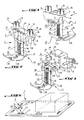
- Figure 1 is a perspective view of a retaining device according to the invention, in its working position.
- FIG. 2 is a perspective view of the fixing device according to FIG. 1, seen in the direction of the arrow II of this FIG.
- Figure 3 is a perspective view of the retainer according to Figure 2, but shows it in a position in which the staple portion is spaced apart.
- FIG. 4 is a side view of the retainer according to FIGS. 1 and 2, in its position, for fixing a flush-fitting element in a location opening of a support plate.
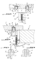
- Figure 5 is a sectional view along the line V-V of Figure 4, with an expansion rivet not yet deformed and a deformed rivet.
- Figures 7 and 8 are schematic views of an expansion rivet before and after the spacing operation.
- the reference numerals 1, 2 and 3 respectively denote a support plate 1, a flush-mounted element supported by its edge on the support plate 1 and a retaining device 3 according to the invention for fixing the embedded part 2 to the support plate 1.
- the slot opening in the plate 1, in which the insertable element 2 is to be mounted, has the reference 4.
- the device retaining 3 comprises a base body 6 advantageously made of plastic.
- the body comprises a substantially parallelepiped medial portion and side flanges 8 which, as well as reinforcing members 9 extending between the flanges and the middle portion.
- the front faces 10 of the fastening flanges 8 form the front or front face of the base body.
- the middle part 7 is made in the form of a hollow block which is open in the plane of its front face and is closed on its rear side by a bottom wall 12.
- a cylindrical hollow pin 14 protrudes from the front face 10 of each flange.
- the lugs can be made in the form of expansion rivets. To this end, each lug is divided in the example shown by two axial notches 15, 16 diametral and extending from the free end of the lug, into four segments 17 radially spaceable apart from each other.
- Each segment of lug or rivet 14 has on its inner face a cam in the form of a ramp 18 projecting progressively towards the axis of the lug, in the direction of the free end.
- Each rivet is associated with a spacer rod 20 which protrudes from the rear face of the corresponding flange and is displaceable by passing through a hole therein axially in the expansion rivet 14. During this movement, the The forward end of the rod slides on the ramp-shaped cams and pushes the ends of the rivet segments 14 radially outwardly against the wall of the rivet receiving hole.
- the expansion rivets 14 are made to be of material with the flanges 8.
- the spacer rods can also be of material with the flanges but are only connected thereto by thin breakable connecting bars 19.
- the parallelepiped central body is articulated at 23, at the rear face, a member in the form of a plate 22 which is pivotable between a position spaced from this rear face and a position in which it is applied against it, as this is shown in Figures 1 and 2.
- This plate is advantageously of material with the base body and the joints are formed for example by two flexible connecting bars 23.
- the wafer 22 carries an L-shaped clip portion 25 made of metal in the present example.
- a branch 26 of the staple portion is formed by two parallel bars whose ends are retained and movable, in the direction of the longitudinal direction, in the recesses 28 of the wafer 22. These recesses are in the vicinity of the ridge longitudinal portion of the wafer 22, which extends parallel to the longitudinal edge which carries the hinge 23.
- the second free branch 29 is intended to engage under the support plate in the working position of the retainer and door at the ends of the teeth curved upwardly, which can penetrate into the underside of the support plate.
- the junction zone 32 of the two branches 28, 29 is configured to serve as a support for the head 33 of a screw 34, which passes through the branch 29, extends between the two bars of the branch 26 and is screwed into a threaded hole 36 in the wafer 22 between the recesses 28.
- the threaded hole passes through the wafer.
- the recesses 28 and the threaded hole 36 are extended by the recesses 37 and 38 respectively in this body.
- the recesses 37 and 38 pass through the thickness thereof, as is clearly shown in FIG. 2.
- the zone in which the recesses 37 and 38 open into the front face of the base body protrudes perpendicularly from the front face and serves for precise positioning of the base body on the underside of the insert. It can still be seen in the figure that the plate 22 bears, on its side facing the base body, elements in the form of hooks. 44 which are lockable in corresponding recesses 45 in the bottom wall of the base body.
- FIG. 5 shows how a retaining device 3 according to the invention is fixed on the insert element 2.
- the retaining device is placed on a bracket 41 under the insert element, by inserting the expansion rivets 14 into holes corresponding one-eyed 43 practiced in the console.
- the spacer rods 20 are pushed axially into the rivets, by a blow on their free end, and separate the segments of the rivets 17 so that the outer surfaces thereof are pressed. against the internal walls of the holes.
- the blow on the rods causes the breaking of the thin links 19 by which the rods are connected to the fastening flanges 8.
- the base body and the wafer of the retainer are made of plastic and the metal staple part. It is of course possible in the context of the invention to make the whole in the same material, for example metal or plastic material.
- the axes of the rivets and rivet receiving holes may have some lateral offset to increase the pre-assembly and assembly forces and that the tightening of the retainer by the screw will cause additional bending. of the base body (reduction of the axis offset), which increases the holding force.
Landscapes
- Engineering & Computer Science (AREA)
- Water Supply & Treatment (AREA)
- Health & Medical Sciences (AREA)
- Life Sciences & Earth Sciences (AREA)
- Hydrology & Water Resources (AREA)
- Public Health (AREA)
- Environmental & Geological Engineering (AREA)
- Connection Of Plates (AREA)
- Insertion Pins And Rivets (AREA)
- Wire Bonding (AREA)
- Dowels (AREA)
- Packages (AREA)
- Lead Frames For Integrated Circuits (AREA)
- Structures Or Materials For Encapsulating Or Coating Semiconductor Devices Or Solid State Devices (AREA)
Claims (8)
- Befestigungssystem für ein Einbauelement (2), mindestens eine Rückhaltevorrichtung (3) umfassend, wobei das Einbauelement (2) in die Öffnung zur Platzierung (4) einer Trägerplatte (1) montierbar ist, und sich mit seinem freien Rand auf der Oberseite dieser abstützt und an der Trägerplatte (1) durch mindestens eines der besagten Rückhalteelemente (3) befestigt werden kann, wobei das besagte Rückhalteelement (3) einen Basiskörper (6) umfasst, der starr auf dem Einbauelement (2) montierbar ist, und einen Abschnitt (22, 25), der mit dem Basiskörper (6) verbunden werden kann und unter der Unterseite der Trägerplatte (1) zur Abstützung gelangt, wobei der Abschnitt (22, 25), der unter der Unterseite der Trägerplatte zur Abstützung gelangt, an den Basiskörper (6) angelenkt ist und in eine Stellung schwenken kann, in der das Einbauelement (2) gemeinsam mit dem besagten Rückhalteelement (3) in die Aufnahmeöffnung (4) eingesetzt werden kann, wobei der Basiskörper (6) hervorstehende Verankerungselemente (14) umfasst, die in die in das Einbauelement (2) eingearbeiteten Öffnungen (43) eingeführt werden können, wobei diese hervorstehenden Verankerungselemente (14) von einem Organ (17) gebildet werden, das sich seitlich in die Öffnung (43) ausdehnt, dadurch gekennzeichnet, dass die hervorstehenden Verankerungselemente (14) und ihre in das Einbauelement (2) eingearbeiteten Öffnungen in Nutzungsstellung etwa senkrecht zur Ebene der Öffnung (4) zur Platzierung der Trägerplatte (1) ausgerichtet sind.
- Befestigungssystem nach Anspruch 1, dadurch gekennzeichnet, dass das Organ zur seitlichen Ausdehnung (14, 17) in Form eines hohlen zylindrischen Zapfens realisiert ist, das sich vorzugsweise aus dem Werkstoff des besagten Sasiskörper (6) entwickelt.
- Befestigungssystem nach Anspruch 2, dadurch gekennzeichnet, dass der Ausdehnungszapfen (14) radiale Abstandssegmente (17) umfasst, und dadurch, dass mit dem Ausdehnungszapfen eine Abstandsstange (20) verbunden ist, die axial in den Ausdehnungszapfen verschiebbar ist, um die Ausdehnung des Ausdehnungszapfens durch Beabstandung der Segmente hervorzurufen.
- Befestigungssystem nach Anspruch 3, dadurch gekennzeichnet, dass die Segmente zur radialen Beabstandung (17) des Ausdehnungszapfens auf den Innenseiten rampenförmige Vorsprünge umfassen, so dass im Zusammenwirken mit der Abstandsstange (20) die Beabstandungswirkung beim Einführen der Stange in den Zapfen hervorgerufen wird.
- Befestigungssystem nach einem der Ansprüche 3 oder 4, dadurch gekennzeichnet, dass die Zapfen zur seitlichen Ausdehnung (14) über die Vorderseite (10) von Befestigungsflanschen (8) des Basiskörpers (6) der Rückhaltevorrichtung (3) überstehen, und dadurch, dass die Abstandsstangen (20) über die Rückseite der Befestigungsflansche (8) überstehen, wobei sie axial mit den Zapfen (14) ausgerichtet sind und in die Zapfen (14) durch eine Öffnung, welche die Flansche (8) durchquert, eingeführt werden können.
- Befestigungssystem nach Anspruch 4, dadurch gekennzeichnet, dass sich die Zapfen zur seitlichen Ausdehnung (14) aus dem Material der Befestigungsflansche (8) entwickeln.
- Befestigungssystem nach Anspruch 6, dadurch gekennzeichnet, dass die Abstandsstangen (20) mit den Befestigungsflanschen (8) durch zerbrechbare Verbindungsstege (19) verbunden sind.
- Befestigungssystem nach Anspruch 6, dadurch gekennzeichnet, dass die verbindungsstege (19) mit den Flanschen (8) und den Abstandsstangen (20) aus einem Stück gefertigt sind.
Applications Claiming Priority (2)
| Application Number | Priority Date | Filing Date | Title |
|---|---|---|---|
| FR9911956A FR2798971B1 (fr) | 1999-09-24 | 1999-09-24 | Agencement de fixation d'un element encastrable dans une ouverture d'emplacement d'une plaque de support |
| FR9911956 | 1999-09-24 |
Publications (2)
| Publication Number | Publication Date |
|---|---|
| EP1087066A1 EP1087066A1 (de) | 2001-03-28 |
| EP1087066B1 true EP1087066B1 (de) | 2006-11-02 |
Family
ID=9550216
Family Applications (1)
| Application Number | Title | Priority Date | Filing Date |
|---|---|---|---|
| EP00402642A Expired - Lifetime EP1087066B1 (de) | 1999-09-24 | 2000-09-22 | Anordnung zur Befestigung eines Einbauelementes in einer Öffnung einer Trägerplatte |
Country Status (5)
| Country | Link |
|---|---|
| EP (1) | EP1087066B1 (de) |
| AT (1) | ATE344354T1 (de) |
| DE (1) | DE60031617T2 (de) |
| ES (1) | ES2275479T3 (de) |
| FR (1) | FR2798971B1 (de) |
Families Citing this family (7)
| Publication number | Priority date | Publication date | Assignee | Title |
|---|---|---|---|---|
| CN1556803A (zh) | 2002-05-07 | 2004-12-22 | LG��ѧ��ʽ���� | 用于电致发光的新有机化合物和使用该化合物的有机电致发光器件 |
| US20160096484A1 (en) * | 2014-10-07 | 2016-04-07 | Continental Automotive Systems, Inc. | Integrated fastener for plastic components |
| US10053847B2 (en) * | 2016-04-12 | 2018-08-21 | Ningbo Afa Kitchen And Bath Co., Ltd. | Kitchen mounting part |
| US10184236B2 (en) * | 2016-04-12 | 2019-01-22 | Ningbo Afa Kitchen And Bath Co., Ltd. | Kitchen mounting part |
| WO2019066753A2 (en) * | 2017-09-26 | 2019-04-04 | Di̇renç Metal Ve Metal Bağlanti Elem. Tas. Üreti̇m Ve Pazarlama Li̇mi̇ted Şi̇rketi̇ | FASTENING LEG FOR SINK |
| IT202100001490A1 (it) * | 2021-01-26 | 2022-07-26 | S&C Sistemi E Composito S R L | Dispositivo per il fissaggio di un lavello |
| IT202200021264A1 (it) * | 2022-10-14 | 2024-04-14 | Marcolini Giuseppe S R L | Gancio di fissaggio di lavelli o similari a piani di base |
Family Cites Families (6)
| Publication number | Priority date | Publication date | Assignee | Title |
|---|---|---|---|---|
| EP0029079A1 (de) * | 1979-11-16 | 1981-05-27 | Mecano-Simmonds GmbH | Befestigungsvorrichtung eines Geräteeinsatzes, insbesondere für Küchen-Arbeitsplatten |
| GB9400125D0 (en) * | 1994-01-06 | 1994-03-02 | Springfast Ltd | Improvements relating to fasteners |
| DE4439906C1 (de) * | 1994-11-08 | 1995-11-30 | Blanco Gmbh & Co Kg | Einrichtung zum Befestigen einer Einbauspüle |
| DE19530365C1 (de) * | 1995-08-18 | 1996-10-02 | Mecano Rapid Gmbh | Geräteeinsatz und Befestigungsvorrichtung |
| AU2669697A (en) * | 1996-04-16 | 1997-11-07 | Fairbairn Reads Trust Company Limited As Trustees Of The Brookhaven Trust | Wall anchoring apparatus |
| DE19802456A1 (de) * | 1998-01-23 | 1999-08-05 | Blanco Gmbh & Co Kg | Vorrichtung zum Befestigen eines Einbaugeräts, wie einer Einbauspüle, in einem Trägerplattenausschnitt |
-
1999
- 1999-09-24 FR FR9911956A patent/FR2798971B1/fr not_active Expired - Fee Related
-
2000
- 2000-09-22 ES ES00402642T patent/ES2275479T3/es not_active Expired - Lifetime
- 2000-09-22 DE DE60031617T patent/DE60031617T2/de not_active Expired - Lifetime
- 2000-09-22 EP EP00402642A patent/EP1087066B1/de not_active Expired - Lifetime
- 2000-09-22 AT AT00402642T patent/ATE344354T1/de not_active IP Right Cessation
Also Published As
| Publication number | Publication date |
|---|---|
| FR2798971B1 (fr) | 2001-11-23 |
| ATE344354T1 (de) | 2006-11-15 |
| FR2798971A1 (fr) | 2001-03-30 |
| EP1087066A1 (de) | 2001-03-28 |
| ES2275479T3 (es) | 2007-06-16 |
| DE60031617T2 (de) | 2007-12-13 |
| DE60031617D1 (de) | 2006-12-14 |
Similar Documents
| Publication | Publication Date | Title |
|---|---|---|
| FR2613454A1 (fr) | Accouplement tubulaire pour solidariser deux tubes coaxiaux, ou pour verrouiller un tube a demeure | |
| FR2698922A1 (fr) | Organe de fixation à riveter. | |
| EP2636815B1 (de) | Bügel zum Befestigen eines Handlaufs eines Geländers auf einem Pfosten | |
| FR2626062A1 (fr) | Systeme de verrouillage et de deverrouillage d'une lampe sur un porte-lampe, plus particulierement pour un dispositif d'eclairage ou de signalisation notamment de vehicule automobile | |
| EP1087066B1 (de) | Anordnung zur Befestigung eines Einbauelementes in einer Öffnung einer Trägerplatte | |
| EP1135621B1 (de) | Klemmbefestigung für kabel, rohre oder dergleichen | |
| EP1087075A1 (de) | Permanente Verankerungsvorrichtung | |
| EP1391361A1 (de) | Verbindungsvorrichtung für eine Betätigungsstange eines Bremskraftverstärkers | |
| FR2974878A1 (fr) | Collier de serrage a charniere | |
| FR2766905A1 (fr) | Profile a rainure(s) pour la mise en place d'au moins un accessoire | |
| EP1336763B1 (de) | Befestigungsmittel mit Klammer | |
| FR2813850A1 (fr) | Ensemble de pieces de robe de carrosserie pour un vehicule avec element de fixation | |
| EP2811222B1 (de) | Einbauleuchte | |
| CA2515573A1 (fr) | Dispositif de fixation a pince | |
| FR2764010A1 (fr) | Dispositif en materiau thermoplastique elastique destine au montage d'une platine support d'un accessoire sur une plaque | |
| EP2006553A1 (de) | Anordnung zum Befestigen eines Teils auf einem anderen | |
| FR2796427A1 (fr) | Dispositif de premontage d'un ecrou pour ensemble de fixation du type vis-ecrou | |
| FR2763657A1 (fr) | Dispositif de fixation d'un element a un support mince | |
| EP0864763B1 (de) | Lösbare Befestigungsvorrichtung insbesondere für ein Karosseriebauteil | |
| EP4086466B1 (de) | Befestigungsvorrichtung | |
| FR2799805A1 (fr) | Dispositif d'ancrage dit permanent | |
| EP0713040A1 (de) | Schelle mit integriertem Dübel zur Wandbefestigung eines Rohres | |
| EP2251554B1 (de) | Vorrichtung zur Befestigung zwischen einer Handkurbelstange eines Rollladens und einem Drehorgan am Ausgang des Rollladenkastens oder an der Handkurbel | |
| FR2883340A1 (fr) | Dispositif de fixation d'un anneau d'arrimage sur un element porteur et support le comportant | |
| EP1498305A1 (de) | Befestigungsvorrichtung des Hintersitzkissens eines Kraftfahrzeuges. |
Legal Events
| Date | Code | Title | Description |
|---|---|---|---|
| PUAI | Public reference made under article 153(3) epc to a published international application that has entered the european phase |
Free format text: ORIGINAL CODE: 0009012 |
|
| AK | Designated contracting states |
Kind code of ref document: A1 Designated state(s): AT BE CH CY DE DK ES FI FR GB GR IE IT LI LU MC NL PT SE |
|
| AX | Request for extension of the european patent |
Free format text: AL;LT;LV;MK;RO;SI |
|
| 17P | Request for examination filed |
Effective date: 20010801 |
|
| AKX | Designation fees paid |
Free format text: AT BE CH CY DE DK ES FI FR GB GR IE IT LI LU MC NL PT SE |
|
| 17Q | First examination report despatched |
Effective date: 20040206 |
|
| RAP1 | Party data changed (applicant data changed or rights of an application transferred) |
Owner name: SCHOCK GMBH Owner name: LISI AUTOMOTIVE RAPID |
|
| RAP1 | Party data changed (applicant data changed or rights of an application transferred) |
Owner name: LISI AUTOMOTIVE RAPID Owner name: SCHOCK & CO. GMBH |
|
| GRAP | Despatch of communication of intention to grant a patent |
Free format text: ORIGINAL CODE: EPIDOSNIGR1 |
|
| GRAS | Grant fee paid |
Free format text: ORIGINAL CODE: EPIDOSNIGR3 |
|
| GRAA | (expected) grant |
Free format text: ORIGINAL CODE: 0009210 |
|
| AK | Designated contracting states |
Kind code of ref document: B1 Designated state(s): AT BE CH CY DE DK ES FI FR GB GR IE IT LI LU MC NL PT SE |
|
| PG25 | Lapsed in a contracting state [announced via postgrant information from national office to epo] |
Ref country code: AT Free format text: LAPSE BECAUSE OF FAILURE TO SUBMIT A TRANSLATION OF THE DESCRIPTION OR TO PAY THE FEE WITHIN THE PRESCRIBED TIME-LIMIT Effective date: 20061102 Ref country code: FI Free format text: LAPSE BECAUSE OF FAILURE TO SUBMIT A TRANSLATION OF THE DESCRIPTION OR TO PAY THE FEE WITHIN THE PRESCRIBED TIME-LIMIT Effective date: 20061102 Ref country code: IE Free format text: LAPSE BECAUSE OF FAILURE TO SUBMIT A TRANSLATION OF THE DESCRIPTION OR TO PAY THE FEE WITHIN THE PRESCRIBED TIME-LIMIT Effective date: 20061102 Ref country code: NL Free format text: LAPSE BECAUSE OF FAILURE TO SUBMIT A TRANSLATION OF THE DESCRIPTION OR TO PAY THE FEE WITHIN THE PRESCRIBED TIME-LIMIT Effective date: 20061102 |
|
| REG | Reference to a national code |
Ref country code: GB Ref legal event code: FG4D Free format text: NOT ENGLISH |
|
| REG | Reference to a national code |
Ref country code: IE Ref legal event code: FG4D Free format text: LANGUAGE OF EP DOCUMENT: FRENCH |
|
| REG | Reference to a national code |
Ref country code: CH Ref legal event code: EP |
|
| REF | Corresponds to: |
Ref document number: 60031617 Country of ref document: DE Date of ref document: 20061214 Kind code of ref document: P |
|
| PG25 | Lapsed in a contracting state [announced via postgrant information from national office to epo] |
Ref country code: SE Free format text: LAPSE BECAUSE OF FAILURE TO SUBMIT A TRANSLATION OF THE DESCRIPTION OR TO PAY THE FEE WITHIN THE PRESCRIBED TIME-LIMIT Effective date: 20070202 Ref country code: DK Free format text: LAPSE BECAUSE OF FAILURE TO SUBMIT A TRANSLATION OF THE DESCRIPTION OR TO PAY THE FEE WITHIN THE PRESCRIBED TIME-LIMIT Effective date: 20070202 |
|
| GBT | Gb: translation of ep patent filed (gb section 77(6)(a)/1977) |
Effective date: 20070122 |
|
| PG25 | Lapsed in a contracting state [announced via postgrant information from national office to epo] |
Ref country code: PT Free format text: LAPSE BECAUSE OF FAILURE TO SUBMIT A TRANSLATION OF THE DESCRIPTION OR TO PAY THE FEE WITHIN THE PRESCRIBED TIME-LIMIT Effective date: 20070402 |
|
| NLV1 | Nl: lapsed or annulled due to failure to fulfill the requirements of art. 29p and 29m of the patents act | ||
| REG | Reference to a national code |
Ref country code: ES Ref legal event code: FG2A Ref document number: 2275479 Country of ref document: ES Kind code of ref document: T3 |
|
| REG | Reference to a national code |
Ref country code: IE Ref legal event code: FD4D |
|
| PLBE | No opposition filed within time limit |
Free format text: ORIGINAL CODE: 0009261 |
|
| STAA | Information on the status of an ep patent application or granted ep patent |
Free format text: STATUS: NO OPPOSITION FILED WITHIN TIME LIMIT |
|
| 26N | No opposition filed |
Effective date: 20070803 |
|
| BERE | Be: lapsed |
Owner name: SCHOCK & CO. G.M.B.H. Effective date: 20070930 Owner name: LISI AUTOMOTIVE RAPID Effective date: 20070930 |
|
| PG25 | Lapsed in a contracting state [announced via postgrant information from national office to epo] |
Ref country code: GR Free format text: LAPSE BECAUSE OF FAILURE TO SUBMIT A TRANSLATION OF THE DESCRIPTION OR TO PAY THE FEE WITHIN THE PRESCRIBED TIME-LIMIT Effective date: 20070203 Ref country code: MC Free format text: LAPSE BECAUSE OF NON-PAYMENT OF DUE FEES Effective date: 20070930 |
|
| REG | Reference to a national code |
Ref country code: CH Ref legal event code: PL |
|
| PG25 | Lapsed in a contracting state [announced via postgrant information from national office to epo] |
Ref country code: CH Free format text: LAPSE BECAUSE OF NON-PAYMENT OF DUE FEES Effective date: 20070930 Ref country code: LI Free format text: LAPSE BECAUSE OF NON-PAYMENT OF DUE FEES Effective date: 20070930 |
|
| PG25 | Lapsed in a contracting state [announced via postgrant information from national office to epo] |
Ref country code: BE Free format text: LAPSE BECAUSE OF NON-PAYMENT OF DUE FEES Effective date: 20070930 |
|
| REG | Reference to a national code |
Ref country code: FR Ref legal event code: ST Effective date: 20080531 |
|
| PG25 | Lapsed in a contracting state [announced via postgrant information from national office to epo] |
Ref country code: FR Free format text: LAPSE BECAUSE OF NON-PAYMENT OF DUE FEES Effective date: 20071001 |
|
| PG25 | Lapsed in a contracting state [announced via postgrant information from national office to epo] |
Ref country code: CY Free format text: LAPSE BECAUSE OF FAILURE TO SUBMIT A TRANSLATION OF THE DESCRIPTION OR TO PAY THE FEE WITHIN THE PRESCRIBED TIME-LIMIT Effective date: 20061102 Ref country code: LU Free format text: LAPSE BECAUSE OF NON-PAYMENT OF DUE FEES Effective date: 20070922 |
|
| PGFP | Annual fee paid to national office [announced via postgrant information from national office to epo] |
Ref country code: IT Payment date: 20190925 Year of fee payment: 20 |
|
| PGFP | Annual fee paid to national office [announced via postgrant information from national office to epo] |
Ref country code: GB Payment date: 20190930 Year of fee payment: 20 |
|
| PGFP | Annual fee paid to national office [announced via postgrant information from national office to epo] |
Ref country code: DE Payment date: 20191129 Year of fee payment: 20 |
|
| PGFP | Annual fee paid to national office [announced via postgrant information from national office to epo] |
Ref country code: ES Payment date: 20191021 Year of fee payment: 20 |
|
| REG | Reference to a national code |
Ref country code: DE Ref legal event code: R071 Ref document number: 60031617 Country of ref document: DE |
|
| REG | Reference to a national code |
Ref country code: GB Ref legal event code: PE20 Expiry date: 20200921 |
|
| PG25 | Lapsed in a contracting state [announced via postgrant information from national office to epo] |
Ref country code: GB Free format text: LAPSE BECAUSE OF EXPIRATION OF PROTECTION Effective date: 20200921 |
|
| REG | Reference to a national code |
Ref country code: ES Ref legal event code: FD2A Effective date: 20210129 |
|
| PG25 | Lapsed in a contracting state [announced via postgrant information from national office to epo] |
Ref country code: ES Free format text: LAPSE BECAUSE OF EXPIRATION OF PROTECTION Effective date: 20200923 |