EP1087088A2 - Vorrichtung zur Ruhestromüberwachung einer sicherheitskritischen Einrichtung - Google Patents
Vorrichtung zur Ruhestromüberwachung einer sicherheitskritischen Einrichtung Download PDFInfo
- Publication number
- EP1087088A2 EP1087088A2 EP00118981A EP00118981A EP1087088A2 EP 1087088 A2 EP1087088 A2 EP 1087088A2 EP 00118981 A EP00118981 A EP 00118981A EP 00118981 A EP00118981 A EP 00118981A EP 1087088 A2 EP1087088 A2 EP 1087088A2
- Authority
- EP
- European Patent Office
- Prior art keywords
- voltage
- tactile sensor
- circuit
- current
- electrical termination
- Prior art date
- Legal status (The legal status is an assumption and is not a legal conclusion. Google has not performed a legal analysis and makes no representation as to the accuracy of the status listed.)
- Granted
Links
- 238000012544 monitoring process Methods 0.000 title claims abstract description 16
- 230000003068 static effect Effects 0.000 title 1
- 238000000034 method Methods 0.000 claims abstract description 4
- 238000011156 evaluation Methods 0.000 claims description 14
- 230000006378 damage Effects 0.000 abstract description 10
- 239000000463 material Substances 0.000 abstract description 9
- 238000011161 development Methods 0.000 description 6
- 238000009434 installation Methods 0.000 description 3
- 239000003990 capacitor Substances 0.000 description 2
- 238000001514 detection method Methods 0.000 description 2
- 229910000831 Steel Inorganic materials 0.000 description 1
- 238000013459 approach Methods 0.000 description 1
- 230000004888 barrier function Effects 0.000 description 1
- 230000006735 deficit Effects 0.000 description 1
- 238000013461 design Methods 0.000 description 1
- 230000007613 environmental effect Effects 0.000 description 1
- 238000005259 measurement Methods 0.000 description 1
- 230000002265 prevention Effects 0.000 description 1
- 230000001681 protective effect Effects 0.000 description 1
- 239000010959 steel Substances 0.000 description 1
- 238000012546 transfer Methods 0.000 description 1
- 230000001960 triggered effect Effects 0.000 description 1
Images

Classifications
-
- F—MECHANICAL ENGINEERING; LIGHTING; HEATING; WEAPONS; BLASTING
- F16—ENGINEERING ELEMENTS AND UNITS; GENERAL MEASURES FOR PRODUCING AND MAINTAINING EFFECTIVE FUNCTIONING OF MACHINES OR INSTALLATIONS; THERMAL INSULATION IN GENERAL
- F16P—SAFETY DEVICES IN GENERAL; SAFETY DEVICES FOR PRESSES
- F16P3/00—Safety devices acting in conjunction with the control or operation of a machine; Control arrangements requiring the simultaneous use of two or more parts of the body
- F16P3/12—Safety devices acting in conjunction with the control or operation of a machine; Control arrangements requiring the simultaneous use of two or more parts of the body with means, e.g. feelers, which in case of the presence of a body part of a person in or near the danger zone influence the control or operation of the machine
-
- E—FIXED CONSTRUCTIONS
- E05—LOCKS; KEYS; WINDOW OR DOOR FITTINGS; SAFES
- E05F—DEVICES FOR MOVING WINGS INTO OPEN OR CLOSED POSITION; CHECKS FOR WINGS; WING FITTINGS NOT OTHERWISE PROVIDED FOR, CONCERNED WITH THE FUNCTIONING OF THE WING
- E05F15/00—Power-operated mechanisms for wings
- E05F15/40—Safety devices, e.g. detection of obstructions or end positions
- E05F15/42—Detection using safety edges
- E05F15/44—Detection using safety edges responsive to changes in electrical conductivity
-
- E—FIXED CONSTRUCTIONS
- E05—LOCKS; KEYS; WINDOW OR DOOR FITTINGS; SAFES
- E05F—DEVICES FOR MOVING WINGS INTO OPEN OR CLOSED POSITION; CHECKS FOR WINGS; WING FITTINGS NOT OTHERWISE PROVIDED FOR, CONCERNED WITH THE FUNCTIONING OF THE WING
- E05F15/00—Power-operated mechanisms for wings
-
- E—FIXED CONSTRUCTIONS
- E05—LOCKS; KEYS; WINDOW OR DOOR FITTINGS; SAFES
- E05Y—INDEXING SCHEME ASSOCIATED WITH SUBCLASSES E05D AND E05F, RELATING TO CONSTRUCTION ELEMENTS, ELECTRIC CONTROL, POWER SUPPLY, POWER SIGNAL OR TRANSMISSION, USER INTERFACES, MOUNTING OR COUPLING, DETAILS, ACCESSORIES, AUXILIARY OPERATIONS NOT OTHERWISE PROVIDED FOR, APPLICATION THEREOF
- E05Y2400/00—Electronic control; Electrical power; Power supply; Power or signal transmission; User interfaces
- E05Y2400/80—User interfaces
- E05Y2400/81—Feedback to user, e.g. tactile
- E05Y2400/818—Visual
- E05Y2400/822—Light emitters, e.g. light emitting diodes [LED]
-
- H—ELECTRICITY
- H02—GENERATION; CONVERSION OR DISTRIBUTION OF ELECTRIC POWER
- H02H—EMERGENCY PROTECTIVE CIRCUIT ARRANGEMENTS
- H02H5/00—Emergency protective circuit arrangements for automatic disconnection directly responsive to an undesired change from normal non-electric working conditions with or without subsequent reconnection
- H02H5/10—Emergency protective circuit arrangements for automatic disconnection directly responsive to an undesired change from normal non-electric working conditions with or without subsequent reconnection responsive to mechanical injury, e.g. rupture of line, breakage of earth connection
Definitions
- the invention relates to a device for quiescent current monitoring a safety critical device according to the characteristics of The preamble of claim 1.
- Such devices for quiescent current monitoring on safety-critical Facilities are well known.
- moving elements such as sliding gates
- security-critical situations occur when closing, if for example a person between the sliding gate and one fixed element could be pinched.
- moving elements based on tactile sensors, the presence of obstacles (people, vehicles or the like) capture and drive after such capture switch off automatically immediately to endanger the To avoid obstacles.
- the tactile sensor points next to the switching device an electrical termination to detect the obstacle on, this electrical termination in a closed circuit lies.
- Quiescent current which, if no obstacle was detected, a constant Has value. Should there be a sudden short circuit or an open circuit occur, this is done by changing the constant quiescent current detected.
- the quiescent current also changes when the Switch short-circuits the electrical termination, so that through this known change in size of the quiescent current when detected of the obstacle a sound process can be triggered.
- a disadvantage is that the current flows through the electrical termination there is a voltage due to of environmental influences at the installation location of the electrical termination prevail, to material destruction on the components involved and their connections and other impairments in the Signal acquisition leads. This not only leads to damage or even to the failure of the tactile sensor, but also to one Frequently required replacement of the sensor, which is undesirable is.
- Such safety-critical devices with the tactile sensor to detect obstacles are usually in one Voltage range operated below the so-called small protective voltage (42 volts).
- Small protective voltage 42 volts
- Established in the power supply are power supplies with 12 volts or 24 volts, so that due to this high Stress values also clear material destruction phenomena are detectable, which lead to the disadvantages already described, that are particularly critical to safety.
- the invention is therefore based on the object of a device for Quiescent current monitoring of a safety-critical device to provide, with the damage or simple means Failures of the tactile sensor can be avoided.
- means for generating the in the closed circuit flowing current provided such that at the electrical At the end there is a maximum voltage of one volt.
- the electrical dimensions are dimensioned Components such that at the electrical termination Voltage in the range of 0.4 volts to 0.8 volts is present. It has pointed out that this voltage range is particularly advantageous is because of the upper limit of material destruction, that occur slightly in the range just above a volt could be excluded even more effectively.
- the lower limit of 0.4 volts has the advantage that for the evaluation whether the tactile Sensor was activated or not, still a sufficiently high one Voltage is available which leads to a correspondingly high level Current in the circuit of calm, which is separated from the current that flows, if the switch is closed after being operated by an obstacle was differentiated.
- the means for generating the in the quiescent current flowing as a voltage source educated.
- this voltage source can by default Voltage considering the size of the electrical termination (in the case of a resistor as an electrical termination, the Resistance value) the current flowing in the closed circuit and at the same time the voltage at the electrical termination limited to the maximum size of one volt. So that is So a simple compliance with the maximum limit for the Given voltage at the electrical termination.
- the means for generating the in the quiescent current flowing as a current source which such a current in the electrical termination of the impress tactile sensor from which the voltage of maximum one volt results.
- the maximum voltage of one volt (or a constant voltage below one volt Value) by appropriate dimensioning of the embossed Current and the value (resistance value) of the electrical termination (Resistance) are observed.
- Both the voltage source and the current source can be used for Example short-circuit proof by means of simple and known per se Operational amplifier circuits can be realized.
- AC voltage sources or alternating current sources are used and the electrical termination is a complex termination that is composed of a real part and an imaginary part.
- Conceivable are also such terminations that a coil (imaginary part) or comprise a capacitor (imaginary part).
- imaging part imaging part
- capacitor imaging part
- both Coils and capacitors are not purely imaginary parts have described, these also include a resistance as a real part.
- the tactile sensor is on an electronic Evaluation unit connected to at least one Has threshold switch and a switching stage. This leaves realize a compact evaluation unit, which in addition to the acquisition of an obstacle using the tactile sensor Evaluation using the threshold switch and triggering a switching operation by means of a switching stage.
- the means (voltage source or Current source) arranged in or outside the electrical evaluation unit.
- This allows the installation location of the means for generating the in the closed circuit current flowing freely chosen and the existing design conditions are adjusted.
- the electronic evaluation unit is generally used as the installation location for the funds selected because a power supply (mains connection) is available here stands and to the movable element on which the tactile Sensor arranged, no energy transfer must take place.
- the voltage on the electrical Connection can be detected and displayed. So there is a visible control given that the voltage is below one volt and at the same time a statement is possible as to whether the tactile sensor is actuated was or not.
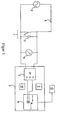
- FIG. 1 shows a device for monitoring the quiescent current safety-critical device or for a safety-critical Facility.
- a safety-critical device it is, for example, sliding gates of fences of areas, slat gates of factory buildings, safety mats or similar. These are preferred areas of application of the invention, but is not limited to this.
- This device has a tactile sensor 1, the one Switch 2, which closes when the tactile sensor 1 is actuated, and comprises a resistor 3 (ohmic resistance).
- the switch 2 can for example consist of two parallel wires, braids or the like, which, for example, in one rubber-like hose assembled into a so-called safety edge are.
- This safety edge is for example on the End face of a sliding gate arranged, when closing the Sliding gates by means of an electric drive motor and opening on an obstacle (for example person) or on Reaching the end position of the sliding gate switch 2 closes. The same applies to the entry of a safety mat by a Person or their leaving.
- a voltage source 5 is provided.
- Current limiting can also be a series resistor 6, but it doesn't have to be.
- the quiescent circuit thus forms the voltage source 5 and the tactile sensor 1 and possibly the series resistor 6. If the series resistor 6 is present, the two resistors form 3 and 6 a voltage divider so that the voltage of the Voltage source 5 as a function of the voltage divider ratio must be chosen that a constant or largely constant voltage of set to a maximum of one volt.
- the use of the voltage divider consisting of resistors 3 and 6 has the advantage that the Voltage across the resistor 3 very precisely due to the Voltage divider ratio by dimensioning the resistors can be set and adhered to. So there is no need to use a very accurate voltage source 5. Possibly the series resistor 6 can also be changed Resistance to be formed with the switch 2 open Voltage across the resistor 3 very precisely with the help of the To be able to adjust voltmeter 4. Another advantage of Voltage divider can be seen in the fact that fluctuations in the Voltage of the voltage source 5 is not or not significantly on the Impact voltage across resistor 3.
- the tactile sensor 1 is connected to an electronic evaluation unit 7, the voltage of resistor 3 initially a threshold switch 8 is supplied. Furthermore, the electronic evaluation unit 7 a power supply 9 (with one Mains voltage of a mains connection, for example 220 volts AC voltage, is converted into a DC voltage supply for the evaluation unit 7) and a display unit 10 with which for example operation, error and output signal of the threshold switch 8 and other sizes can be displayed. About that In addition, the evaluation unit 7 can comprise further elements that are necessary for the operation, but to describe the Quiescent current monitoring is unnecessary and therefore not shown.
- the output signal of the threshold switch 8, for example is designed as a Schmitt trigger, a switching stage 11 is supplied.
- the threshold switch 8 operates in dependence on the input signal in such a way that, for example with switch 2 open no output signal and thus the Switching stage 11 is not controlled. If the switch 2 by detection of an obstacle, the threshold switch 8 an output signal to the switching stage 11, which is a switching operation triggers.
- the switching stage 11 for example a relay, as in Figure 1 hinted at
- an actuator 12 is connected, each switched on or off after use.
- the actuator 12 is an electric motor with which the sliding gate is opened or closed. When closing this electric motor is switched on, the electric motor can be switched off immediately when using the tactile Sensor 1 on the sliding gate an obstacle or the end position of the sliding gate was detected.
- Figure 2 shows a device for quiescent current monitoring with a Current source
- the current source 5 shown in Figure 1 and the Series resistor 6 are replaced by a current source 13, the one impresses constant current in the resistor 3.
- This stream is like that dimensioned that depending on the value of the resistance 3 with the voltmeter 4 a maximum voltage of one Volts, preferably a voltage from the voltage range of 0.4 to 0.8 volts is displayed. Should be the size of the embossed Current can be of importance, this can be done with an ammeter 14 recorded and displayed.
- Figures 1 and 2 is a simple embodiment of devices shown for quiescent current monitoring. To increase the Security is conceivable, one element or several elements redundant, that is, preferably double.
- tactile sensors should act on such sensors, in particular on touch or approach react.
- a touch sensitive Area such as a safety mat, a light barrier or (in general) another recording body to record a physical size which is present when approaching or Touch or (generally) generates a signal in a corresponding manner
- the switch 2 which is also designed, for example, as a relay can be operated.
Landscapes
- Engineering & Computer Science (AREA)
- General Engineering & Computer Science (AREA)
- Mechanical Engineering (AREA)
- Geophysics And Detection Of Objects (AREA)
- Testing Of Devices, Machine Parts, Or Other Structures Thereof (AREA)
- Protection Of Static Devices (AREA)
- Selective Calling Equipment (AREA)
- Power-Operated Mechanisms For Wings (AREA)
Abstract
Description
- Figur 1:
- eine Vorrichtung zur Ruhestromüberwachung mit einer Spannungsquelle und
- Figur 2:
- eine Vorrichtung zur Ruhestromüberwachung mit einer Stromquelle.
- 1.
- Taktiler Sensor
- 2.
- Schalter
- 3.
- Widerstand
- 4.
- Spannungsmesser
- 5.
- Spannungsquelle
- 6.
- Vorwiderstand
- 7.
- Elektronische Auswerteeinheit
- 8.
- Schwellwertschalter
- 9.
- Stromversorgung
- 10.
- Anzeigeeinheit
- 11.
- Schaltstufe
- 12.
- Aktuator
- 13.
- Stromquelle
- 14.
- Strommesser
Claims (7)
- Vorrichtung zur Ruhestromüberwachung einer sicherheitskritischen Einrichtung mit einem taktilen Sensor (1), der einen elektrischen Abschluß (3) aufweist, wobei der in dem Ruhestromkreis fließende Strom durch Betätigung des taktilen Sensors (1) veränderbar ist und diese Veränderung einen Schaltvorgang auslöst,
gekennzeichnet durch Mittel zur Erzeugung des in dem Ruhestromkreis fließenden Stromes derart, daß an dem elektrischen Abschluß (3) eine Spannung von maximal einem Volt anliegt. - Vorrichtung nach Anspruch 1,
dadurch gekennzeichnet, daß an dem elektrischen Abschluß (3) eine Spannung im Bereich von 0,4 Volt bis 0,8 Volt anliegt. - Vorrichtung nach Anspruch 1 oder 2,
dadurch gekennzeichnet, daß die Mittel zur Erzeugung des in dem Ruhestromkreis fließenden Stromes als Spannungsquelle (5) ausgebildet sind. - Vorrichtung nach Anspruch 1 oder 2,
dadurch gekennzeichnet, daß die Mittel zur Erzeugung des in dem Ruhestromkreis fließenden Stromes als Stromquelle (13) ausgebildet sind, die einen solchen Strom in den elektrischen Abschluß (3) des taktilen Sensors (1) einprägen, aus dem die Spannung von maximal einem Volt resultiert. - Vorrichtung nach einem der vorhergehenden Ansprüche,
dadurch gekennzeichnet, daß der taktile Sensor (1) an einer elektronischen Auswerteeinheit (7) angeschlossen ist, die zumindest einen Schwellwertschalter (8) sowie eine Schaltstufe (11) aufweist. - Vorrichtung nach Anspruch 5,
dadurch gekennzeichnet, daß die Mittel zur Erzeugung des in dem Ruhestromkreis fließenden Stromes in oder außerhalb der elektrischen Auswerteeinheit (7) angeordnet sind. - Vorrichtung nach einem der vorhergehenden Ansprüche,
dadurch gekennzeichnet, daß die Spannung an dem elektrischen Abschluß (3) erfaßbar und anzeigbar ist.
Applications Claiming Priority (2)
| Application Number | Priority Date | Filing Date | Title |
|---|---|---|---|
| DE19946039A DE19946039A1 (de) | 1999-09-25 | 1999-09-25 | Vorrichtung zur Ruhestromüberwachung einer sicherheitskritischen Einrichtung |
| DE19946039 | 1999-09-25 |
Publications (3)
| Publication Number | Publication Date |
|---|---|
| EP1087088A2 true EP1087088A2 (de) | 2001-03-28 |
| EP1087088A3 EP1087088A3 (de) | 2007-03-21 |
| EP1087088B1 EP1087088B1 (de) | 2008-03-26 |
Family
ID=7923313
Family Applications (1)
| Application Number | Title | Priority Date | Filing Date |
|---|---|---|---|
| EP00118981A Expired - Lifetime EP1087088B1 (de) | 1999-09-25 | 2000-09-01 | Vorrichtung zur Ruhestromüberwachung einer sicherheitskritischen Einrichtung |
Country Status (4)
| Country | Link |
|---|---|
| EP (1) | EP1087088B1 (de) |
| AT (1) | ATE390534T1 (de) |
| DE (2) | DE19946039A1 (de) |
| ES (1) | ES2304338T3 (de) |
Cited By (1)
| Publication number | Priority date | Publication date | Assignee | Title |
|---|---|---|---|---|
| EP1146528A3 (de) * | 2000-04-14 | 2004-04-28 | Karlheinz Beckhausen | Elektrisches Kontaktmatte mit Vorrichtung zur Ruhestromüberwachung |
Family Cites Families (4)
| Publication number | Priority date | Publication date | Assignee | Title |
|---|---|---|---|---|
| DE3527405A1 (de) * | 1985-07-31 | 1987-02-12 | Bosch Gmbh Robert | Vorrichtung zum schutz von personen gegen einklemmen in motorisch verschliessbaren oeffnungen in kraftfahrzeugen |
| DE8710266U1 (de) * | 1987-07-27 | 1987-12-03 | Karosseriewerke Weinsberg Gmbh, 7102 Weinsberg | Kindersicherung für Schiebe-Hebefenster von Kraftfahrzeugen |
| FR2642894B1 (fr) * | 1989-02-08 | 1993-11-26 | Jaeger | Systeme detecteur d'obstacle muni de moyens d'autotest |
| DE4337059A1 (de) * | 1993-10-29 | 1995-05-04 | Klemens Schlachter | Anordnung zur Notabschaltung eines motorischen Antriebes zum Schließen von Dreh- und/oder Kippfenstern |
-
1999
- 1999-09-25 DE DE19946039A patent/DE19946039A1/de not_active Withdrawn
-
2000
- 2000-09-01 EP EP00118981A patent/EP1087088B1/de not_active Expired - Lifetime
- 2000-09-01 ES ES00118981T patent/ES2304338T3/es not_active Expired - Lifetime
- 2000-09-01 DE DE50015055T patent/DE50015055D1/de not_active Expired - Lifetime
- 2000-09-01 AT AT00118981T patent/ATE390534T1/de active
Cited By (1)
| Publication number | Priority date | Publication date | Assignee | Title |
|---|---|---|---|---|
| EP1146528A3 (de) * | 2000-04-14 | 2004-04-28 | Karlheinz Beckhausen | Elektrisches Kontaktmatte mit Vorrichtung zur Ruhestromüberwachung |
Also Published As
| Publication number | Publication date |
|---|---|
| ES2304338T3 (es) | 2008-10-16 |
| DE19946039A1 (de) | 2001-03-29 |
| EP1087088A3 (de) | 2007-03-21 |
| ATE390534T1 (de) | 2008-04-15 |
| EP1087088B1 (de) | 2008-03-26 |
| DE50015055D1 (de) | 2008-05-08 |
Similar Documents
| Publication | Publication Date | Title |
|---|---|---|
| EP2760774B1 (de) | Vorrichtung und verfahren zum überwachen von schachttüren | |
| DE3003877A1 (de) | Einklemmsicherungseinrichtung fuer automatisch betaetigbare tueren oder fenster, insbesondere an fahrzeugen | |
| WO2014114669A2 (de) | Kapazitiver näherungssensor | |
| DE69211573T2 (de) | Verdrahtungsfehlerdetektor für einen Türbetätiger | |
| DE19540620A1 (de) | Überwachung der Bewegung eines antreibbaren, ein- oder mehrteiligen Tür- oder Torblattes | |
| DE102013221138A1 (de) | Verfahren und Vorrichtung zur Überwachung eines Rückleiterkabels eines Bahngleises | |
| DE102017201955A1 (de) | Bremsvorrichtung | |
| DE1907587A1 (de) | Verfahren und Vorrichtung zur Unterdrueckung von falschem Alarm in einem elektrischen Schutzsystem | |
| DE102020111807B9 (de) | Elektrische Schaltungsanordnung und Verfahren zur Funktionsprüfung eines Überwachungsgeräts für ein elektrisches Stromversorgungssystem | |
| DE3809960C2 (de) | ||
| EP2136343B1 (de) | Leitungsüberwachung von Rauchschaltern | |
| EP3361620B1 (de) | Bremsvorrichtung | |
| EP1087088A2 (de) | Vorrichtung zur Ruhestromüberwachung einer sicherheitskritischen Einrichtung | |
| EP0468361B1 (de) | Begrenzung der Schliesskraft an der Schliesskante eines beweglichen Elementes | |
| EP3361621A1 (de) | Bremsvorrichtung | |
| DE69503823T2 (de) | Kraftfahrzeugfensterheber mit Einklemmschutz und verringerter Anzahl von Anschlussdrähten | |
| DE102008018642A1 (de) | Überwachungsschaltung und Verfahren zum Prüfen der Schaltung | |
| DE2747614C2 (de) | Schutzvorrichtung, insbesondere zum Schutz beim Arbeiten in Bereichen stark schwankender Lichtintensität, mit einer Testschaltung | |
| DE102013112815A1 (de) | Sicherheitssteuerung | |
| EP1128516B2 (de) | Verfahren zur Erzeugung eines Klemmschutzsignals und Klemmschutzvorrichtung | |
| DE19545254C2 (de) | Anordnung zur dauerhaft betriebssicheren Anschaltung eines Kontaktsatzes einer elektromechanischen Schaltkontakteinrichtung | |
| EP0054581A1 (de) | Antrieb zum Betätigen von Türen oder Toren | |
| DE2659470B2 (de) | Scharfschalteeinrichtung für eine Einbruch-Meldeanlage | |
| EP2456073B1 (de) | Vieradriger Sicherheits-Hall-Schalter | |
| DE4302035A1 (de) | Antriebssteuerung |
Legal Events
| Date | Code | Title | Description |
|---|---|---|---|
| PUAI | Public reference made under article 153(3) epc to a published international application that has entered the european phase |
Free format text: ORIGINAL CODE: 0009012 |
|
| AK | Designated contracting states |
Kind code of ref document: A2 Designated state(s): AT BE CH CY DE DK ES FI FR GB GR IE IT LI LU MC NL PT SE |
|
| AX | Request for extension of the european patent |
Free format text: AL;LT;LV;MK;RO;SI |
|
| PUAL | Search report despatched |
Free format text: ORIGINAL CODE: 0009013 |
|
| AK | Designated contracting states |
Kind code of ref document: A3 Designated state(s): AT BE CH CY DE DK ES FI FR GB GR IE IT LI LU MC NL PT SE |
|
| AX | Request for extension of the european patent |
Extension state: AL LT LV MK RO SI |
|
| 17P | Request for examination filed |
Effective date: 20070508 |
|
| GRAP | Despatch of communication of intention to grant a patent |
Free format text: ORIGINAL CODE: EPIDOSNIGR1 |
|
| AKX | Designation fees paid |
Designated state(s): AT BE CH CY DE DK ES FI FR GB GR IE IT LI LU MC NL PT SE |
|
| GRAS | Grant fee paid |
Free format text: ORIGINAL CODE: EPIDOSNIGR3 |
|
| GRAA | (expected) grant |
Free format text: ORIGINAL CODE: 0009210 |
|
| AK | Designated contracting states |
Kind code of ref document: B1 Designated state(s): AT BE CH CY DE DK ES FI FR GB GR IE IT LI LU MC NL PT SE |
|
| REG | Reference to a national code |
Ref country code: GB Ref legal event code: FG4D Free format text: NOT ENGLISH |
|
| REG | Reference to a national code |
Ref country code: CH Ref legal event code: EP Ref country code: IE Ref legal event code: FG4D Free format text: LANGUAGE OF EP DOCUMENT: GERMAN |
|
| REF | Corresponds to: |
Ref document number: 50015055 Country of ref document: DE Date of ref document: 20080508 Kind code of ref document: P |
|
| REG | Reference to a national code |
Ref country code: SE Ref legal event code: TRGR |
|
| PG25 | Lapsed in a contracting state [announced via postgrant information from national office to epo] |
Ref country code: FI Free format text: LAPSE BECAUSE OF FAILURE TO SUBMIT A TRANSLATION OF THE DESCRIPTION OR TO PAY THE FEE WITHIN THE PRESCRIBED TIME-LIMIT Effective date: 20080326 |
|
| REG | Reference to a national code |
Ref country code: CH Ref legal event code: NV Representative=s name: R. A. EGLI & CO. PATENTANWAELTE |
|
| NLV1 | Nl: lapsed or annulled due to failure to fulfill the requirements of art. 29p and 29m of the patents act | ||
| REG | Reference to a national code |
Ref country code: ES Ref legal event code: FG2A Ref document number: 2304338 Country of ref document: ES Kind code of ref document: T3 |
|
| REG | Reference to a national code |
Ref country code: IE Ref legal event code: FD4D |
|
| PG25 | Lapsed in a contracting state [announced via postgrant information from national office to epo] |
Ref country code: PT Free format text: LAPSE BECAUSE OF FAILURE TO SUBMIT A TRANSLATION OF THE DESCRIPTION OR TO PAY THE FEE WITHIN THE PRESCRIBED TIME-LIMIT Effective date: 20080901 |
|
| PG25 | Lapsed in a contracting state [announced via postgrant information from national office to epo] |
Ref country code: NL Free format text: LAPSE BECAUSE OF FAILURE TO SUBMIT A TRANSLATION OF THE DESCRIPTION OR TO PAY THE FEE WITHIN THE PRESCRIBED TIME-LIMIT Effective date: 20080326 |
|
| ET | Fr: translation filed | ||
| PG25 | Lapsed in a contracting state [announced via postgrant information from national office to epo] |
Ref country code: DK Free format text: LAPSE BECAUSE OF FAILURE TO SUBMIT A TRANSLATION OF THE DESCRIPTION OR TO PAY THE FEE WITHIN THE PRESCRIBED TIME-LIMIT Effective date: 20080326 Ref country code: IE Free format text: LAPSE BECAUSE OF FAILURE TO SUBMIT A TRANSLATION OF THE DESCRIPTION OR TO PAY THE FEE WITHIN THE PRESCRIBED TIME-LIMIT Effective date: 20080326 |
|
| PLBE | No opposition filed within time limit |
Free format text: ORIGINAL CODE: 0009261 |
|
| STAA | Information on the status of an ep patent application or granted ep patent |
Free format text: STATUS: NO OPPOSITION FILED WITHIN TIME LIMIT |
|
| 26N | No opposition filed |
Effective date: 20081230 |
|
| BERE | Be: lapsed |
Owner name: BECKHAUSEN, KARLHEINZ Effective date: 20080930 |
|
| PG25 | Lapsed in a contracting state [announced via postgrant information from national office to epo] |
Ref country code: MC Free format text: LAPSE BECAUSE OF NON-PAYMENT OF DUE FEES Effective date: 20080930 |
|
| PG25 | Lapsed in a contracting state [announced via postgrant information from national office to epo] |
Ref country code: BE Free format text: LAPSE BECAUSE OF NON-PAYMENT OF DUE FEES Effective date: 20080930 |
|
| PG25 | Lapsed in a contracting state [announced via postgrant information from national office to epo] |
Ref country code: CY Free format text: LAPSE BECAUSE OF FAILURE TO SUBMIT A TRANSLATION OF THE DESCRIPTION OR TO PAY THE FEE WITHIN THE PRESCRIBED TIME-LIMIT Effective date: 20080326 |
|
| PG25 | Lapsed in a contracting state [announced via postgrant information from national office to epo] |
Ref country code: LU Free format text: LAPSE BECAUSE OF NON-PAYMENT OF DUE FEES Effective date: 20080901 |
|
| REG | Reference to a national code |
Ref country code: GB Ref legal event code: 732E Free format text: REGISTERED BETWEEN 20100826 AND 20100901 |
|
| PG25 | Lapsed in a contracting state [announced via postgrant information from national office to epo] |
Ref country code: GR Free format text: LAPSE BECAUSE OF FAILURE TO SUBMIT A TRANSLATION OF THE DESCRIPTION OR TO PAY THE FEE WITHIN THE PRESCRIBED TIME-LIMIT Effective date: 20080627 |
|
| REG | Reference to a national code |
Ref country code: CH Ref legal event code: PUE Owner name: GELBAU GMBH & CO. KG Free format text: BECKHAUSEN, KARLHEINZ#LANDGRAFENSTRASSE 109#50931 KOELN (DE) -TRANSFER TO- GELBAU GMBH & CO. KG#GRANDKAULE 8-10#53859 NIEDERKASSEL (DE) |
|
| REG | Reference to a national code |
Ref country code: FR Ref legal event code: TP |
|
| REG | Reference to a national code |
Ref country code: FR Ref legal event code: PLFP Year of fee payment: 17 |
|
| REG | Reference to a national code |
Ref country code: FR Ref legal event code: PLFP Year of fee payment: 18 |
|
| PGFP | Annual fee paid to national office [announced via postgrant information from national office to epo] |
Ref country code: IT Payment date: 20170929 Year of fee payment: 18 Ref country code: DE Payment date: 20170810 Year of fee payment: 18 Ref country code: FR Payment date: 20170925 Year of fee payment: 18 |
|
| PGFP | Annual fee paid to national office [announced via postgrant information from national office to epo] |
Ref country code: SE Payment date: 20170918 Year of fee payment: 18 Ref country code: AT Payment date: 20170905 Year of fee payment: 18 |
|
| REG | Reference to a national code |
Ref country code: DE Ref legal event code: R082 Ref document number: 50015055 Country of ref document: DE Representative=s name: CARSTENSEN & CARSTENSEN PATENTANWAELTE PARTG M, DE |
|
| PGFP | Annual fee paid to national office [announced via postgrant information from national office to epo] |
Ref country code: CH Payment date: 20171227 Year of fee payment: 18 Ref country code: ES Payment date: 20171002 Year of fee payment: 18 Ref country code: GB Payment date: 20171002 Year of fee payment: 18 |
|
| REG | Reference to a national code |
Ref country code: DE Ref legal event code: R119 Ref document number: 50015055 Country of ref document: DE |
|
| REG | Reference to a national code |
Ref country code: SE Ref legal event code: EUG Ref country code: CH Ref legal event code: PL |
|
| REG | Reference to a national code |
Ref country code: AT Ref legal event code: MM01 Ref document number: 390534 Country of ref document: AT Kind code of ref document: T Effective date: 20180901 |
|
| GBPC | Gb: european patent ceased through non-payment of renewal fee |
Effective date: 20180901 |
|
| PG25 | Lapsed in a contracting state [announced via postgrant information from national office to epo] |
Ref country code: SE Free format text: LAPSE BECAUSE OF NON-PAYMENT OF DUE FEES Effective date: 20180902 |
|
| PG25 | Lapsed in a contracting state [announced via postgrant information from national office to epo] |
Ref country code: DE Free format text: LAPSE BECAUSE OF NON-PAYMENT OF DUE FEES Effective date: 20190402 Ref country code: IT Free format text: LAPSE BECAUSE OF NON-PAYMENT OF DUE FEES Effective date: 20180901 |
|
| PG25 | Lapsed in a contracting state [announced via postgrant information from national office to epo] |
Ref country code: LI Free format text: LAPSE BECAUSE OF NON-PAYMENT OF DUE FEES Effective date: 20180930 Ref country code: FR Free format text: LAPSE BECAUSE OF NON-PAYMENT OF DUE FEES Effective date: 20180930 Ref country code: CH Free format text: LAPSE BECAUSE OF NON-PAYMENT OF DUE FEES Effective date: 20180930 |
|
| PG25 | Lapsed in a contracting state [announced via postgrant information from national office to epo] |
Ref country code: AT Free format text: LAPSE BECAUSE OF NON-PAYMENT OF DUE FEES Effective date: 20180901 Ref country code: GB Free format text: LAPSE BECAUSE OF NON-PAYMENT OF DUE FEES Effective date: 20180901 |
|
| REG | Reference to a national code |
Ref country code: ES Ref legal event code: FD2A Effective date: 20191129 |
|
| PG25 | Lapsed in a contracting state [announced via postgrant information from national office to epo] |
Ref country code: ES Free format text: LAPSE BECAUSE OF NON-PAYMENT OF DUE FEES Effective date: 20180902 |