EP1087143A2 - Pompe submersible - Google Patents
Pompe submersible Download PDFInfo
- Publication number
- EP1087143A2 EP1087143A2 EP00120160A EP00120160A EP1087143A2 EP 1087143 A2 EP1087143 A2 EP 1087143A2 EP 00120160 A EP00120160 A EP 00120160A EP 00120160 A EP00120160 A EP 00120160A EP 1087143 A2 EP1087143 A2 EP 1087143A2
- Authority
- EP
- European Patent Office
- Prior art keywords
- submersible pump
- housing
- pump
- drive motors
- liquid
- Prior art date
- Legal status (The legal status is an assumption and is not a legal conclusion. Google has not performed a legal analysis and makes no representation as to the accuracy of the status listed.)
- Granted
Links
- 239000007788 liquid Substances 0.000 claims description 21
- 239000012530 fluid Substances 0.000 description 2
- 238000010276 construction Methods 0.000 description 1
- 230000004048 modification Effects 0.000 description 1
- 238000012986 modification Methods 0.000 description 1
- 238000005086 pumping Methods 0.000 description 1
- 125000006850 spacer group Chemical group 0.000 description 1
- XLYOFNOQVPJJNP-UHFFFAOYSA-N water Substances O XLYOFNOQVPJJNP-UHFFFAOYSA-N 0.000 description 1
Images

Classifications
-
- F—MECHANICAL ENGINEERING; LIGHTING; HEATING; WEAPONS; BLASTING
- F04—POSITIVE - DISPLACEMENT MACHINES FOR LIQUIDS; PUMPS FOR LIQUIDS OR ELASTIC FLUIDS
- F04D—NON-POSITIVE-DISPLACEMENT PUMPS
- F04D1/00—Radial-flow pumps, e.g. centrifugal pumps; Helico-centrifugal pumps
- F04D1/06—Multi-stage pumps
-
- F—MECHANICAL ENGINEERING; LIGHTING; HEATING; WEAPONS; BLASTING
- F04—POSITIVE - DISPLACEMENT MACHINES FOR LIQUIDS; PUMPS FOR LIQUIDS OR ELASTIC FLUIDS
- F04D—NON-POSITIVE-DISPLACEMENT PUMPS
- F04D13/00—Pumping installations or systems
- F04D13/02—Units comprising pumps and their driving means
- F04D13/06—Units comprising pumps and their driving means the pump being electrically driven
- F04D13/08—Units comprising pumps and their driving means the pump being electrically driven for submerged use
- F04D13/086—Units comprising pumps and their driving means the pump being electrically driven for submerged use the pump and drive motor are both submerged
-
- H—ELECTRICITY
- H02—GENERATION; CONVERSION OR DISTRIBUTION OF ELECTRIC POWER
- H02K—DYNAMO-ELECTRIC MACHINES
- H02K7/00—Arrangements for handling mechanical energy structurally associated with dynamo-electric machines, e.g. structural association with mechanical driving motors or auxiliary dynamo-electric machines
- H02K7/14—Structural association with mechanical loads, e.g. with hand-held machine tools or fans
-
- F—MECHANICAL ENGINEERING; LIGHTING; HEATING; WEAPONS; BLASTING
- F05—INDEXING SCHEMES RELATING TO ENGINES OR PUMPS IN VARIOUS SUBCLASSES OF CLASSES F01-F04
- F05D—INDEXING SCHEME FOR ASPECTS RELATING TO NON-POSITIVE-DISPLACEMENT MACHINES OR ENGINES, GAS-TURBINES OR JET-PROPULSION PLANTS
- F05D2250/00—Geometry
- F05D2250/30—Arrangement of components
- F05D2250/31—Arrangement of components according to the direction of their main axis or their axis of rotation
- F05D2250/312—Arrangement of components according to the direction of their main axis or their axis of rotation the axes being parallel to each other
Definitions
- the present invention relates to an electrically operated submersible pump with a Casing.
- Submersible pumps of this type are known in a large number of embodiments.
- the known submersible pumps each have a pump stage consisting of a Drive motor and an impeller operated with it to convey liquids on.
- Such submersible pumps are used in particular in supply and Water systems for caravans, motorhomes, boats or other, correspondingly small dimensioned fittings.
- a disadvantage of the known submersible pumps is that often not the safe one and reliable pumping of fluids required pressure can be built up can. Especially in cases where the liquid reservoir with the submersible pump is far from the liquid outlet, d. H. the valve is removed, it occurs in this area Problems, since the submersible pumps are not of any size in these application areas can be dimensioned.
- each pump stage has a drive motor which drives a respective impeller and the Drive motors are arranged side by side within the housing.
- the drive motors are offset arranged side by side. This makes it possible to transport the volume of the Fluid to vary since the two pump stages or the two Drive motors within the housing have different spaces for the liquid create.
- the submersible pump has a Intake opening for a liquid in the area of the first pump stage and one Liquid outlet at the end of the housing opposite the suction opening on.
- the drive motors are designed to be switchable independently of one another. That’s it possible, both pump stages simultaneously or separately, depending on the corresponding Requirements to operate.
- FIG. 1 shows an electrically operated submersible pump 10 with a housing 12.
- two, communicating, i.e. H. in Liquid-connected pump stages 14, 16 are formed.
- Each Pump stage 14, 16 has a drive motor 18, 20, each of which has a Shaft drives a corresponding impeller 22, 24.
- the Drive motors 18, 20 arranged side by side and offset within the housing 12 are.
- the first pump stage 14 is arranged above one in the housing base 40 Suction opening 26 arranged. About the suction opening 26 is to be transported Liquid is sucked in and into the space 36 below the drive motors 18, 20 promoted. The delivery pressure exerted by the two pump stages 14, 16 increases the Total pressure or total delivery pressure of the system. The one to be transported Liquid then rises via a liquid channel 30 to one in the housing cover 42 trained liquid outlet 28. It can be seen that the liquid channel between the pump stages 14, 16 is formed. He is lateral in the embodiment moved backwards.
- the submersible pump is usually operated with 12 V D.C ..
- the drive motors 18, 20 are therefore connected to a corresponding one via electrical lines 32, 34 Energy source connected.
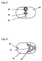
- Figure 2 shows a plan view of the submersible pump 10. It can be seen that in the cover 42 liquid outlet 28, a cable duct 46 and a vent opening 44 are formed.
- Figure 3 shows a schematic view of the submersible pump 10 from below. You can see that spacers 38 are arranged on the outside of the housing base (cf. also FIG 1). The arrangement of the suction opening 26 can also be seen.
Landscapes
- Engineering & Computer Science (AREA)
- Mechanical Engineering (AREA)
- General Engineering & Computer Science (AREA)
- Power Engineering (AREA)
- Structures Of Non-Positive Displacement Pumps (AREA)
- Control Of Non-Positive-Displacement Pumps (AREA)
Applications Claiming Priority (2)
| Application Number | Priority Date | Filing Date | Title |
|---|---|---|---|
| DE29916897U DE29916897U1 (de) | 1999-09-24 | 1999-09-24 | Tauchpumpe |
| DE29916897U | 1999-09-24 |
Publications (3)
| Publication Number | Publication Date |
|---|---|
| EP1087143A2 true EP1087143A2 (fr) | 2001-03-28 |
| EP1087143A3 EP1087143A3 (fr) | 2001-04-18 |
| EP1087143B1 EP1087143B1 (fr) | 2004-12-01 |
Family
ID=8079431
Family Applications (1)
| Application Number | Title | Priority Date | Filing Date |
|---|---|---|---|
| EP00120160A Revoked EP1087143B1 (fr) | 1999-09-24 | 2000-09-21 | Pompe submersible |
Country Status (2)
| Country | Link |
|---|---|
| EP (1) | EP1087143B1 (fr) |
| DE (2) | DE29916897U1 (fr) |
Cited By (1)
| Publication number | Priority date | Publication date | Assignee | Title |
|---|---|---|---|---|
| CN110685929A (zh) * | 2019-11-14 | 2020-01-14 | 合肥恒大江海泵业股份有限公司 | 一种矿用潜水电泵 |
Families Citing this family (2)
| Publication number | Priority date | Publication date | Assignee | Title |
|---|---|---|---|---|
| DE10039117C2 (de) * | 2000-08-07 | 2003-04-30 | Comet Pumpen Systemtechnik Gmb | Tauchpumpenanordnung |
| DE102012204212B4 (de) * | 2012-03-16 | 2024-02-29 | Mahle International Gmbh | Pumpenmodul mit einem Gehäuse |
Family Cites Families (5)
| Publication number | Priority date | Publication date | Assignee | Title |
|---|---|---|---|---|
| FR2019894A1 (fr) * | 1968-10-04 | 1970-07-10 | Ercole Marelli Et C | |
| DE1808411C3 (de) * | 1968-11-12 | 1973-08-16 | Jochen Dipl Ing Oplaender | Pumpenaggregat aus zwei in einem gehaeuse angeordneten kreiselpumpen |
| DD136759A1 (de) | 1978-05-29 | 1979-07-25 | Hans Spengler | Hochdruckkreiselpumpenaggregat |
| DE2824523A1 (de) | 1978-06-03 | 1979-12-06 | Coleman Co | Zweistufige kreiselpumpe |
| DE4239071C2 (de) | 1992-11-20 | 1997-01-30 | Grundfos As | Tauchpumpenaggregat |
-
1999
- 1999-09-24 DE DE29916897U patent/DE29916897U1/de not_active Expired - Lifetime
-
2000
- 2000-09-21 EP EP00120160A patent/EP1087143B1/fr not_active Revoked
- 2000-09-21 DE DE50008816T patent/DE50008816D1/de not_active Revoked
Cited By (1)
| Publication number | Priority date | Publication date | Assignee | Title |
|---|---|---|---|---|
| CN110685929A (zh) * | 2019-11-14 | 2020-01-14 | 合肥恒大江海泵业股份有限公司 | 一种矿用潜水电泵 |
Also Published As
| Publication number | Publication date |
|---|---|
| DE29916897U1 (de) | 2000-01-20 |
| EP1087143B1 (fr) | 2004-12-01 |
| EP1087143A3 (fr) | 2001-04-18 |
| DE50008816D1 (de) | 2005-01-20 |
Similar Documents
| Publication | Publication Date | Title |
|---|---|---|
| DE3800336C2 (fr) | ||
| DE3820003A1 (de) | Tauchpumpenaggregat | |
| DE102019115778A1 (de) | Pumpe, insbesondere Pumpe für einen Flüssigkeitskreislauf in einem Fahrzeug | |
| DE102018125040A1 (de) | Pumpe, insbesondere für einen Flüssigkeitskreislauf in einem Fahrzeug | |
| DE2249510A1 (de) | Fluessigkeitspumpenaggregat, insbesondere fuer den einsatz in geschirrspuelmaschinen | |
| EP1087143B1 (fr) | Pompe submersible | |
| EP1862674B1 (fr) | Pompe centrifuge | |
| DE102013101164A1 (de) | Schraubenspindelpumpe | |
| EP2721301A1 (fr) | Pompe submersible et procédé d'assemblage d'une pompe submersible | |
| DE69520262T2 (de) | Mehrstufige elektrische Kreiselpumpe | |
| DE102007036238A1 (de) | Flüssigkeitspumpe | |
| DE19905435B4 (de) | Tauchpumpe | |
| DE4415566C2 (de) | Seitenkanalpumpe | |
| EP0171656B1 (fr) | Compresseur à anneau liquide | |
| DE3623096A1 (de) | Selbstansaugende pumpe | |
| DE102018122305A1 (de) | Pumpenaggregat zur Bereitstellung eines Hydraulikdrucks zur Betätigung eines Aktors im Antriebsstrang eines Kraftfahrzeugs | |
| EP1249611B1 (fr) | Pompe avec clapet de non-retour | |
| DE3429137A1 (de) | Turbomolekularpumpe | |
| EP1666726A2 (fr) | Système modulaire pour pompes à fluides | |
| EP3945218B1 (fr) | Pompe centrifuge | |
| EP1006282A2 (fr) | Ensemble motopompe autoamorçante | |
| DE4140731C2 (de) | Waschanlage, insbesondere für Scheiben eines Kraftfahrzeugs | |
| DE323817C (de) | Mehrstufige Kreiselpumpe | |
| DE3314651C2 (de) | Vakuumpumpe | |
| DE102018125037A1 (de) | Pumpe, insbesondere für einen Flüssigkeitskreislauf in einem Fahrzeug |
Legal Events
| Date | Code | Title | Description |
|---|---|---|---|
| PUAI | Public reference made under article 153(3) epc to a published international application that has entered the european phase |
Free format text: ORIGINAL CODE: 0009012 |
|
| PUAL | Search report despatched |
Free format text: ORIGINAL CODE: 0009013 |
|
| AK | Designated contracting states |
Kind code of ref document: A2 Designated state(s): DE FR GB IT NL |
|
| AX | Request for extension of the european patent |
Free format text: AL;LT;LV;MK;RO;SI |
|
| AK | Designated contracting states |
Kind code of ref document: A3 Designated state(s): AT BE CH CY DE DK ES FI FR GB GR IE IT LI LU MC NL PT SE |
|
| AX | Request for extension of the european patent |
Free format text: AL;LT;LV;MK;RO;SI |
|
| 17P | Request for examination filed |
Effective date: 20011005 |
|
| AKX | Designation fees paid |
Free format text: DE FR GB IT NL |
|
| 17Q | First examination report despatched |
Effective date: 20030129 |
|
| GRAP | Despatch of communication of intention to grant a patent |
Free format text: ORIGINAL CODE: EPIDOSNIGR1 |
|
| GRAS | Grant fee paid |
Free format text: ORIGINAL CODE: EPIDOSNIGR3 |
|
| GRAA | (expected) grant |
Free format text: ORIGINAL CODE: 0009210 |
|
| AK | Designated contracting states |
Kind code of ref document: B1 Designated state(s): DE FR GB IT NL |
|
| REG | Reference to a national code |
Ref country code: GB Ref legal event code: FG4D Free format text: NOT ENGLISH |
|
| REF | Corresponds to: |
Ref document number: 50008816 Country of ref document: DE Date of ref document: 20050120 Kind code of ref document: P |
|
| GBT | Gb: translation of ep patent filed (gb section 77(6)(a)/1977) |
Effective date: 20050407 |
|
| PLBI | Opposition filed |
Free format text: ORIGINAL CODE: 0009260 |
|
| PLAX | Notice of opposition and request to file observation + time limit sent |
Free format text: ORIGINAL CODE: EPIDOSNOBS2 |
|
| 26 | Opposition filed |
Opponent name: COMET-PUMPEN SYSTEMTECHNIK GMBH & CO. KG Effective date: 20050829 |
|
| ET | Fr: translation filed | ||
| NLR1 | Nl: opposition has been filed with the epo |
Opponent name: COMET-PUMPEN SYSTEMTECHNIK GMBH & CO. KG |
|
| PLBB | Reply of patent proprietor to notice(s) of opposition received |
Free format text: ORIGINAL CODE: EPIDOSNOBS3 |
|
| PLCK | Communication despatched that opposition was rejected |
Free format text: ORIGINAL CODE: EPIDOSNREJ1 |
|
| PLAG | Information modified related to despatch of communication that opposition is rejected |
Free format text: ORIGINAL CODE: EPIDOSCREJ1 |
|
| PLAG | Information modified related to despatch of communication that opposition is rejected |
Free format text: ORIGINAL CODE: EPIDOSCREJ1 |
|
| APBM | Appeal reference recorded |
Free format text: ORIGINAL CODE: EPIDOSNREFNO |
|
| APBP | Date of receipt of notice of appeal recorded |
Free format text: ORIGINAL CODE: EPIDOSNNOA2O |
|
| APAH | Appeal reference modified |
Free format text: ORIGINAL CODE: EPIDOSCREFNO |
|
| APBQ | Date of receipt of statement of grounds of appeal recorded |
Free format text: ORIGINAL CODE: EPIDOSNNOA3O |
|
| PGFP | Annual fee paid to national office [announced via postgrant information from national office to epo] |
Ref country code: NL Payment date: 20090921 Year of fee payment: 10 Ref country code: GB Payment date: 20090922 Year of fee payment: 10 |
|
| PGFP | Annual fee paid to national office [announced via postgrant information from national office to epo] |
Ref country code: DE Payment date: 20090930 Year of fee payment: 10 |
|
| APBU | Appeal procedure closed |
Free format text: ORIGINAL CODE: EPIDOSNNOA9O |
|
| PGFP | Annual fee paid to national office [announced via postgrant information from national office to epo] |
Ref country code: IT Payment date: 20090924 Year of fee payment: 10 |
|
| RDAF | Communication despatched that patent is revoked |
Free format text: ORIGINAL CODE: EPIDOSNREV1 |
|
| RDAG | Patent revoked |
Free format text: ORIGINAL CODE: 0009271 |
|
| STAA | Information on the status of an ep patent application or granted ep patent |
Free format text: STATUS: PATENT REVOKED |
|
| 27W | Patent revoked |
Effective date: 20100318 |
|
| GBPR | Gb: patent revoked under art. 102 of the ep convention designating the uk as contracting state |
Effective date: 20100318 |
|
| PGFP | Annual fee paid to national office [announced via postgrant information from national office to epo] |
Ref country code: FR Payment date: 20091007 Year of fee payment: 10 |