EP1087155B1 - Vorrichtung zur Steuerung einer Getriebebaueinheit - Google Patents
Vorrichtung zur Steuerung einer Getriebebaueinheit Download PDFInfo
- Publication number
- EP1087155B1 EP1087155B1 EP00120499A EP00120499A EP1087155B1 EP 1087155 B1 EP1087155 B1 EP 1087155B1 EP 00120499 A EP00120499 A EP 00120499A EP 00120499 A EP00120499 A EP 00120499A EP 1087155 B1 EP1087155 B1 EP 1087155B1
- Authority
- EP
- European Patent Office
- Prior art keywords
- control device
- transmission module
- transmission
- preselector
- triggering
- Prior art date
- Legal status (The legal status is an assumption and is not a legal conclusion. Google has not performed a legal analysis and makes no representation as to the accuracy of the status listed.)
- Expired - Lifetime
Links
- 230000005540 biological transmission Effects 0.000 title claims description 70
- 230000008878 coupling Effects 0.000 claims description 18
- 238000010168 coupling process Methods 0.000 claims description 18
- 238000005859 coupling reaction Methods 0.000 claims description 18
- 238000001514 detection method Methods 0.000 claims description 15
- 238000012545 processing Methods 0.000 claims description 7
- 238000000034 method Methods 0.000 claims description 5
- 230000008569 process Effects 0.000 claims description 5
- 230000003287 optical effect Effects 0.000 claims description 3
- 238000013461 design Methods 0.000 description 6
- 230000008901 benefit Effects 0.000 description 4
- 238000013519 translation Methods 0.000 description 4
- 230000008859 change Effects 0.000 description 3
- 238000006243 chemical reaction Methods 0.000 description 3
- 238000004891 communication Methods 0.000 description 2
- 230000007547 defect Effects 0.000 description 2
- 238000011161 development Methods 0.000 description 2
- 230000007935 neutral effect Effects 0.000 description 2
- 238000012546 transfer Methods 0.000 description 2
- 230000015572 biosynthetic process Effects 0.000 description 1
- 238000005315 distribution function Methods 0.000 description 1
- 230000000694 effects Effects 0.000 description 1
- 230000010354 integration Effects 0.000 description 1
- 230000035515 penetration Effects 0.000 description 1
- 230000009467 reduction Effects 0.000 description 1
Images
Classifications
-
- F—MECHANICAL ENGINEERING; LIGHTING; HEATING; WEAPONS; BLASTING
- F16—ENGINEERING ELEMENTS AND UNITS; GENERAL MEASURES FOR PRODUCING AND MAINTAINING EFFECTIVE FUNCTIONING OF MACHINES OR INSTALLATIONS; THERMAL INSULATION IN GENERAL
- F16H—GEARING
- F16H59/00—Control inputs to control units of change-speed- or reversing-gearings for conveying rotary motion
- F16H59/02—Selector apparatus
- F16H59/08—Range selector apparatus
- F16H59/12—Range selector apparatus comprising push button devices
Definitions
- the invention relates to a device for controlling a gear unit, in particular for electronic control, specifically with the features from the preamble of claim 1.
- a certain predefinable Translation range from a theoretically possible Total translation range can be covered. This is done by Subdivision of the driving states into different under driving states, whereby corresponding actuators for this to choose from are provided.
- These underrun states are characterized in that in Driving state “forward drive” and / or “reverse drive” actually only on certain range of what is theoretically possible Transmission range of the gear unit by part of theoretically possible gear steps is covered.
- the automatic transmission module six gears then there is Possibility for the driver to specify whether everyone is in the "Forward” driving state six gears should be used, or whether only a certain number of the lower gears to be run.
- the control of the gear unit in particular individual Components for optimizing the transmission behavior or others Tasks can also depend on a number of other tasks Input variables take place.
- Input variables take place.
- the functioning of individual components in the Drivetrain at least indirectly descriptive variables for control the gear unit.
- Generated signals can, for example, via a higher-level Vehicle control generated and fed to the transmission control.
- the electronic transmission control device therefore has a variety of Inputs and outputs, which with the appropriate actuators and Sensors for realizing the individual driving conditions are coupled.
- the pre-selection device alone for specifying a driver request a variety of electrical for a given driving condition
- Connections to the electronic transmission control are required and the electronic transmission control device not necessarily in the area of Gear assembly is arranged are usually a variety of long Connection lines between the gear unit and the provide electronic transmission control device.
- an automatic transmission for motor vehicles known to which an electronic transmission control unit is assigned. Further an electrical gear selection element is provided, which in spatial Distance to the transmission control unit is arranged and for example via a Can bus can be connected to the gearbox control unit.
- the electrical Gear selection element is in a switch block, for example, in one Integrated steering wheel and includes a control panel and a selector control unit. This serves to generate corresponding signals from the actuation of the Control unit.
- the output of the selector control unit communicates with the transmission control unit. In this version, it is above the Selector lever predetermined signal at a control device in immediate spatial proximity processed.
- the coupling with the gearbox control unit can be via Can bus or a separate line.
- the invention is therefore based on the object of a device for control to further develop a gear unit of the type mentioned at the beginning, that the disadvantages mentioned are avoided.
- the control device should more inexpensive to provide and easy to retrofit and replace his.
- the device for electrical control has a Gear unit an electronic assigned to the gear unit Control device, usually a control unit for the gear unit and a preselection device for specifying a driver request for a specific one Driving state, with the preselection device a second control device is directly assigned. Between the first electronic control device and second electronic control device is at least one electrical coupling intended.
- the second electrical control device is used for recording and processing using electrical signals generated by the preselector and forwarding to the electronic control device of the Transmission unit. All that is needed to pass on the individual signals is one serial transmission means, for example in the form of a CAN bus or one Optical waveguide.
- control device Under control device, the whole is generally made up Control device, actuators and detection devices and the Connection lines understood this while control device in the Usually the structural component includes the control unit.
- the options mentioned under b) and c) represent two particular features preferred versions, since these in addition to a minimum Components and required line connections very short Line connections between the preselection device and the control device require.
- the second electronic control device comprises preferably at least one microprocessor.
- the individual input variables are then from the second electronic Control device processed and the output of the second Control device passed on to the first control device, which the Actuating variables to control or act on the actuators of the forms individual gear elements.
- the Actuating variables to control or act on the actuators of the forms individual gear elements are then from the second electronic Control device processed and the output of the second Control device passed on to the first control device, which the Actuating variables to control or act on the actuators of the forms individual gear elements.
- the Actuating variables to control or act on the actuators of the forms individual gear elements are then from the second electronic Control device processed and the output of the second Control device passed on to the first control device, which the Actuating variables to control or act on the actuators of the forms individual gear elements.
- the option of Formation of some of the manipulated variables already in the second control device are also be formed of some of the manipulated variables already in the second control device.
- the solution according to the invention is for any arrangement Gear unit and the gear electronics suitable for each other.
- she offers the advantage that the transmission electronics regardless of the arrangement of the Gear unit in the vehicle compared to the vehicle electronics always in Gearbox proximity, preferably integrated in the gearbox housing can.
- the second electronic control device Most of the required vehicle signals, which are usually other electronic via a common interface Control devices can be fed to the first control device They are usually provided to bridge a larger one spatial distance required wiring between the second and the number of the first control device is kept low.
- Another major advantage is that when integrating the first Transmission control device in the transmission module only a few electrical Lines must be led into the gear unit, that is, that the component expenditure for the electronics to be integrated is kept low and the number of implementing agencies required is also minimal is.
- the coupling between the second electronic control device and the individual detection devices for detecting the to control the Gearbox unit specifiable setpoints at least indirectly Descriptive sizes and / or the required actual values for Description of how individual elements of the drive system work and / or the operating conditions of the environment can be varied be carried out. This also applies to the implementation respectively Generation of the in the second electronic control device processing electrical signals.
- the actuators can, for example, as buttons, switches (Toggle or slide switch) and lever.
- This Actuators are either individually or together Detection means for recording the functional positions of the individual Actuators and / or the actuation of an actuating element generally assigned.
- Detection means are then designed such that an actuation of a any or special actuating element, for example by a mechanical size, e.g. a path, angle or force can be characterized which causes the sensor to respond.
- the actuation at least indirectly to use descriptive variables, for example in the form of pulses, optical or acoustic signals.
- the one designed according to the invention is Device for controlling a gear unit with a parent Driving control coupled to the vehicle.
- the invention can Device can be integrated in the higher-level driving control.
- Another Possibility is that the coupling with the parent Driving control by linking one of the two electronic ones Control devices with the higher-level driving control. Conceivable it is also based on a general coupling with the parent To do without driving control and only the individual determined sizes one shared by a variety of control devices To provide communication interface in the form of a CAN bus. In this Case there is a possibility that certain sizes are no longer generally direct made available to the individual control devices at their inputs must be, but this from a higher-level Can bus can be read out, which the current data either directly from the Receiving means or other control devices.
- the solution according to the invention is for any kind of automatic Gear units regardless of the type of implementation of the speed / torque conversion used.
- This can be hydrodynamic, mechanically, hydrostatically or electrically.
- Another second Control device is provided, which the signals of the vehicle side Boundary conditions and / or the driver's request at least indirectly descriptive sizes processed and the transmission control device processed and / or determined from them available.
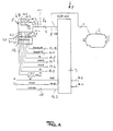
- FIG. 1 illustrates in a schematically simplified Representation of the basic structure and the functioning of an invention designed device 1 for the electronic control of a Gear unit 2, comprising an electronic control device 3 for the gear unit 2 and a preselection device 4 for specifying a Driver request for a specific driving condition to control the Gear unit 2 by controlling in particular the switching elements and / or the hydrodynamic power transmission or Conversion devices of the gear unit 2.
- the preselection device 4 forms a second control device 5 of the Device 1 for controlling a gear unit 2.
- Die Preselection device 4 and the second control device 5 are functional summarized and form an ECU. This means that at least includes a microprocessor. This second control device 5 takes over a so-called collection and distribution function.
- the one in a conventional System of a transmission control of this self-processed Input signals and generated output signals are now according to the invention at least in part via the second control device read or output.
- the transfer to the real one Transmission control that is, the control device of the transmission assembly 2 takes place via an electrical coupling 6, which is preferably at least one serial transmission means 7 comprises.
- This can take the form, for example a so-called CAN bus 8, which at least a line for coupling the individual electronic control devices 3 and 5 includes.
- This line 8 serves primarily for communication of the individual control devices, first control device 3 and second Control device 5 with each other.
- the vehicle CAN bus can be used as an option Find use.
- the second control device takes over her Inputs 9.1 to 9.n different input variables and converts them into a form readable for the first control device 3 and sends it Message on the CAN bus, or line 8. It can also further outputs, not shown here, are provided, via which the second control device 5 can interact with other systems. Input variables are recorded, in one, for the first control device Readable form converted, and as a message via the serial Transmission means 7 (preferably implemented as a CAN bus). Conversely, manipulated variables from the transmitted the first control device to the second control device, there decoded and the corresponding outputs controlled. For realization an emergency function if the CAN bus fails and / or Plausibility check there is the possibility of using an additional Transmission means, which, for. B.
- the preselection device 4 directly as the second Control device 5 is executed includes the second electronic Control device 5 at least one microprocessor 10, the at least the, the actuation of the individual actuating elements 11.1 to 11.n the Preselection 4 at least indirectly describing sizes Processing to be fed. Between the actuators 11.1 to 11.n and the microprocessor 10 thus consist at least of the electrical ones Couplings 12.1 to 12.n.
- the Preselection device 4 for example, with a key switch device at least three predeterminable driving conditions, "idle”, “reverse travel” and “Forward travel”, with the total range of the theoretically possible transmission range of the gear unit 2 is exploited.
- the pushbutton switch therefore has an electrical coupling 12.1 to 12.3 with the microprocessor. These also form inputs 9.1 to 9.3.
- the second electronic control device 5 is on the vehicle side additional signals can be supplied for processing. These are via the inputs 9.4 to 9.10 fed to the second electronic control device 5. there run in a device 13, which is referred to as an electronics compartment electrical connections to other components of the vehicle together. However, these connections are not absolutely necessary.
- signals are connected which the Functional state of individual drive components or the Ambient conditions of individual components in the drive train describe at least indirectly. These are used by appropriate Detection elements supplied.
- the inputs 9.4 to 9.10 are for this purpose corresponding detection means 14.4 to 14.n at least indirectly coupled.
- the detection means are used, for example, for detection at least one, the functional state (for example driving, Braking mode) and / or the mode of operation of a hydrodynamic retarder at least indirectly describing the functional state of a Parking brake device at least indirectly descriptive size and / or one, the mode of operation and / or the operating state of a Drive component at least indirectly descriptive size.
- the first control device 3 can be in close proximity to the Gear unit 2 may be arranged. However, this is preferably done Arrangement in the gear housing 2. In this case, only the implementation the implementation and supply of the electrical coupling 6, in particular a line or the pair of lines 8 through a housing Gear unit 2 and a passage of the other lines to Realization of an electrical connection between the inputs 16.2 to 16.n and the corresponding recording means for recording the to processing sizes and the Can-Bus as well as the power supply 16.5 and 16.6 required.
- the first control device 3 is arranged spatial proximity to the gear unit 2 are only the individual electrical connections between the first electronic Control device 3 and the actuators for actuating the individual Switching elements for realizing a change in the driving state and the Control device 3 and the transmission sensors in the transmission module 2 required.
- the inventive design of a device for controlling a Gear unit is not based on a concrete design limited. It is only essential to the invention that in addition to the actual electronic control device for controlling the individual Gear elements of the gear unit a further second control device is provided which is otherwise used to control the gear unit imperative sizes and processes and the result the first electronic control device to a minimum Line strands, preferably only one line, for example, too a pair of leads.
- the preselection device is preferably used Specification of a specific driver request to change the driving state designed as a second control device. This offers the advantage of spatial assignment of the vehicle electronics and the Preselector to each other, regardless of the arrangement of the Gear unit in the vehicle.
Landscapes
- Engineering & Computer Science (AREA)
- General Engineering & Computer Science (AREA)
- Mechanical Engineering (AREA)
- Control Of Transmission Device (AREA)
Description
- 1
- Vorrichtung zur Steuerung einer Getriebebaueinheit
- 2
- Getriebebaueinheit
- 3
- Erste Steuereinrichtung zur Ansteuerung der Getriebebaueinheit
- 4
- Vorwahleinrichtung zur Vorgabe eines Fahrerwunsches zur Änderung eines Fahrzustandes
- 5
- Zweite Steuereinrichtung
- 6
- Elektrische Kopplung
- 7
- Serielle Übertragungsmittel
- 8
- Leitung, Leitungspaar
- 9.1-9.n
- Eingänge
- 10
- Mikroprozessor
- 11.1-11.n
- Betätigungselemente
- 12.1-12.n
- Elektrische Kopplung zwischen den Betätigungselementen und dem Mikroprozessor
- 13
- Elektronikfach
- 14.1-14.n
- Erfassungsmittel
- 15
- Can-Bus
- 16.1-16.n
- Eingänge und Ausgänge der ersten Steuereinrichtung
Claims (10)
- Vorrichtung zur elektrischen Steuerung einer Getriebebaueinheit (2)
mit einer ersten elektronischen Steuereinrichtung (3) für die Ansteuerung der Getriebeelemente der Getriebebaueinheit (2)
mit einer Vorwahleinrichtung (4) zur Vorgabe eines Fahrerwunsches für einen der nachfolgend genannten Fahrzustände zur Ansteuerung der Getriebebaueinheit: (2)mit einer zweiten Steuereinrichtung (5), welche der Vorwahleinrichtung (4) unmittelbar zugeordnet ist und wenigstens die mittels der Vorwahleinrichtung vorgegebenen Größen zur Ansteuerung der Getriebebaueinheit (2) verarbeitet;"Leerlauf""Rückwärtsfahrt""Vorwärtsfahrt"
die zweite Steuereinrichtung (5) weist wenigstens einen Ausgang auf, welcher mit einem Eingang (16.1) zu der ersten Steuereinrichtung (3) elektrisch gekoppelt ist;
die Vorwahleinrichtung (4) und die zweite elektronische Steuereinrichtung (5) bilden eine bauliche Einheit; dadurch gekennzeichnet, daß
der zweiten elektronischen Steuereinrichtung (5) fahrzeugseitig weitere Signale zur Verarbeitung zuführbar sind, welche den Funktionszustand einzelner Antriebskomponenten beziehungsweise die Umgebungsbedingungen einzelner Komponenten im Antriebsstrang wenigstens mittelbar beschreiben. - Getriebebaueinheit nach Anspruch 1, dadurch gekennzeichnet, daß die zweite Steuereinrichtung (5) von der Vorwahleinrichtung (4) gebildet wird.
- Vorrichtung nach einem der Ansprüche 1 oder 2, dadurch gekennzeichnet, daß die elektrische Kopplung zwischen dem Ausgang der zweiten elektrischen Steuereinrichtung (5) und dem ersten Eingang (16.1) der ersten elektrischen Steuereinrichtung (3) wenigstens ein serielles Übertragungsmittel umfaßt.
- Vorrichtung nach Anspruch 3, dadurch gekennzeichnet, daß das serielle Übertragungsmittel weinigstens eine Leitung oder ein Leitungspaar (8) in Form eines Can-Buses umfaßt.
- Vorrichtung nach Anspruch 3, dadurch gekennzeichnet, daß die elektrische Kopplung wenigstens einen Lichtwellenleiter umfaßt
- Vorrichtung nach einem der Ansprüche 1 bis 5, dadurch gekennzeichnet, daß die erste Steuereinrichtung in der Getriebebaueinheit(2) integriert ist
- Vorrichtung nach einem der Ansprüche 1 bis 5, dadurch gekennzeichnet, daß die erste Steuereinrichtung (3) in unmittelbarer räumlicher Nähe der Getriebebaueinheit (2) angeordnet ist.
- Vorrichtung nach einem der Ansprüche 1 bis 7, dadurch gekennzeichnet, daß die zweite Steuereinrichtung eine Vielzahl von weiteren Eingängen (9.4 bis 9.n) aufweist, welche mit Erfassungsmitteln zur wenigstens mittelbaren Erfassung der Betriebsweise und/oder des Funktionszustandes von Antriebskomponenten des Antriebsstranges und/oder Erfassungsmitteln zur Erfassung der Umgebungsbedingungen und oder Erfassungsmittel zur Erfassung des Fahrerwunsches der Antriebskomponenten gekoppelt sind.
- Vorrichtung nach einem der Ansprüche 1 bis 8, dadurch gekennzeichnet, daß die Vorwahleinrichtung weitere Mittel zur Vorgabe wenigstens eines der nachfolgend genannten Fahrzustände zur Ansteuerung der Getriebebaueinheit (2) umfaßt:"Vorwärtsfahrt" unter Ausnutzung wenigstens eines Teilbereiches des mittels der theoretisch möglichen Gangstufung überstreichbaren Gesamtbetriebsbereiches der Getriebebaueinheit und/oder"Sperrung der theoretisch möglichen Gangstufen".
- Vorrichtung nach Anspruch 8 dadurch gekennzeichnet, daß an einem Ausgang der zweiten Steuereinrichtung wenigstens ein Signal zur Ansteuerung der Gebtriebebaueinheit zur Realisierung eines Notfahrbetriebes und/oder Plausibilitätsprüfung erzeugbar ist.
Applications Claiming Priority (2)
| Application Number | Priority Date | Filing Date | Title |
|---|---|---|---|
| DE19945352A DE19945352A1 (de) | 1999-09-22 | 1999-09-22 | Vorrichtung zur Steuerung einer Getriebebaueinheit |
| DE19945352 | 1999-09-22 |
Publications (3)
| Publication Number | Publication Date |
|---|---|
| EP1087155A2 EP1087155A2 (de) | 2001-03-28 |
| EP1087155A3 EP1087155A3 (de) | 2002-08-14 |
| EP1087155B1 true EP1087155B1 (de) | 2004-08-11 |
Family
ID=7922865
Family Applications (1)
| Application Number | Title | Priority Date | Filing Date |
|---|---|---|---|
| EP00120499A Expired - Lifetime EP1087155B1 (de) | 1999-09-22 | 2000-09-20 | Vorrichtung zur Steuerung einer Getriebebaueinheit |
Country Status (2)
| Country | Link |
|---|---|
| EP (1) | EP1087155B1 (de) |
| DE (2) | DE19945352A1 (de) |
Families Citing this family (1)
| Publication number | Priority date | Publication date | Assignee | Title |
|---|---|---|---|---|
| CN115654117B (zh) * | 2022-09-29 | 2024-04-26 | 重庆金康赛力斯新能源汽车设计院有限公司 | 挡位切换控制方法、装置、计算机设备和存储介质 |
Family Cites Families (6)
| Publication number | Priority date | Publication date | Assignee | Title |
|---|---|---|---|---|
| JPS62299435A (ja) * | 1986-06-19 | 1987-12-26 | Isuzu Motors Ltd | 異常検出装置付き車両の制御装置 |
| WO1995005951A1 (de) * | 1993-08-26 | 1995-03-02 | Siemens Aktiengesellschaft | Steuerung für ein kraftfahrzeug |
| JPH08320064A (ja) * | 1995-05-25 | 1996-12-03 | Aisin Aw Co Ltd | 位置検出装置 |
| DE19736931C2 (de) * | 1997-08-25 | 2003-05-08 | Zf Sachs Ag | Antriebsanordnung |
| JPH11141664A (ja) * | 1997-11-06 | 1999-05-25 | Hitachi Ltd | 自動変速機用制御装置 |
| DE19810479A1 (de) * | 1998-03-11 | 1999-09-16 | Bayerische Motoren Werke Ag | Automatikgetriebe in Kraftfahrzeugen |
-
1999
- 1999-09-22 DE DE19945352A patent/DE19945352A1/de not_active Ceased
-
2000
- 2000-09-20 EP EP00120499A patent/EP1087155B1/de not_active Expired - Lifetime
- 2000-09-20 DE DE50007356T patent/DE50007356D1/de not_active Expired - Lifetime
Also Published As
| Publication number | Publication date |
|---|---|
| DE50007356D1 (de) | 2004-09-16 |
| EP1087155A2 (de) | 2001-03-28 |
| DE19945352A1 (de) | 2001-04-19 |
| EP1087155A3 (de) | 2002-08-14 |
Similar Documents
| Publication | Publication Date | Title |
|---|---|---|
| DE4392671C2 (de) | Kommunikationssystem für Kraftfahrzeuge | |
| EP0807772B1 (de) | Verfahren zum Betreiben eines Fahrzeugs mit mehreren Antriebsmaschinen | |
| DE102012113126B4 (de) | Elektronische Schaltvorrichtung eines Fahrzeugs | |
| DE10351968A1 (de) | Schaltsystem für ein Fahrzeug | |
| DE102004009469A1 (de) | Redundantes Bremssteuerungssystem für ein Fahrzeug | |
| WO2006061238A1 (de) | Elektromechanische feststell-bremsanlage und elektronisches system zum betreiben derselben | |
| EP1781499B1 (de) | Nutzfahrzeug mit mehreren jeweils von mindestens einem elektronischen steuergerät gesteuerten elektrischen einrichtungen | |
| DD297737A5 (de) | Verkabelungssystem fuer fahrzeuge | |
| DE10008455A1 (de) | Vorrichtung zur Durchführung von Steuerungs- oder Regelungsfunktionen und Verfahren zur Steuerung oder Regelung bei einem Fahrzeug | |
| DE19963782B4 (de) | Steuerung für ein Fahrzeug mit einer Getriebesteuerung | |
| DE19622529A1 (de) | Ansteuereinrichtung | |
| WO2008003429A1 (de) | Schnittstellenvorrichtung | |
| DE102004056123A1 (de) | Nutzfahrzeug | |
| EP1087155B1 (de) | Vorrichtung zur Steuerung einer Getriebebaueinheit | |
| EP1254328B1 (de) | Getriebe mit zentraler kupplungsausrückung | |
| DE19948969A1 (de) | Steuervorrichtung für einen aus Motor und Getriebe bestehenden Fahrzeugantriebsstrang | |
| DE102008029891B4 (de) | Kraftfahrzeug mit Shift-By-Wire-System | |
| DE60312569T2 (de) | Schaltungsarchitektur eines gangschalters für ein automatisches getriebe | |
| EP1054192A1 (de) | Getriebebaueinheit und Vorrichtung zur elektronischen Steuerung einer Getriebebaueinheit | |
| DE10044892B4 (de) | Verfahren zum Betrieb einer multifunktionalen Anzeigeeinrichtung | |
| EP3394478A1 (de) | Schaltwähl- und parksperren-system | |
| WO2011127890A1 (de) | Vorrichtung zur betätigung von kraftfahrzeugkomponenten | |
| WO2003029040A1 (de) | Modul für aktuatoren in einem fahrzeug | |
| DE10004020A1 (de) | Fahrzeugverkabelung | |
| WO2001098689A1 (de) | Elektronische getriebesteuerung |
Legal Events
| Date | Code | Title | Description |
|---|---|---|---|
| PUAI | Public reference made under article 153(3) epc to a published international application that has entered the european phase |
Free format text: ORIGINAL CODE: 0009012 |
|
| AK | Designated contracting states |
Kind code of ref document: A2 Designated state(s): AT BE CH CY DE DK ES FI FR GB GR IE IT LI LU MC NL PT SE |
|
| AX | Request for extension of the european patent |
Free format text: AL;LT;LV;MK;RO;SI |
|
| PUAL | Search report despatched |
Free format text: ORIGINAL CODE: 0009013 |
|
| AK | Designated contracting states |
Kind code of ref document: A3 Designated state(s): AT BE CH CY DE DK ES FI FR GB GR IE IT LI LU MC NL PT SE |
|
| AX | Request for extension of the european patent |
Free format text: AL;LT;LV;MK;RO;SI |
|
| 17P | Request for examination filed |
Effective date: 20020715 |
|
| 17Q | First examination report despatched |
Effective date: 20020924 |
|
| AKX | Designation fees paid |
Designated state(s): DE FR IT |
|
| GRAP | Despatch of communication of intention to grant a patent |
Free format text: ORIGINAL CODE: EPIDOSNIGR1 |
|
| GRAS | Grant fee paid |
Free format text: ORIGINAL CODE: EPIDOSNIGR3 |
|
| GRAA | (expected) grant |
Free format text: ORIGINAL CODE: 0009210 |
|
| AK | Designated contracting states |
Kind code of ref document: B1 Designated state(s): DE FR IT |
|
| PG25 | Lapsed in a contracting state [announced via postgrant information from national office to epo] |
Ref country code: IT Free format text: LAPSE BECAUSE OF FAILURE TO SUBMIT A TRANSLATION OF THE DESCRIPTION OR TO PAY THE FEE WITHIN THE PRESCRIBED TIME-LIMIT;WARNING: LAPSES OF ITALIAN PATENTS WITH EFFECTIVE DATE BEFORE 2007 MAY HAVE OCCURRED AT ANY TIME BEFORE 2007. THE CORRECT EFFECTIVE DATE MAY BE DIFFERENT FROM THE ONE RECORDED. Effective date: 20040811 Ref country code: FR Free format text: LAPSE BECAUSE OF FAILURE TO SUBMIT A TRANSLATION OF THE DESCRIPTION OR TO PAY THE FEE WITHIN THE PRESCRIBED TIME-LIMIT Effective date: 20040811 |
|
| REG | Reference to a national code |
Ref country code: IE Ref legal event code: FG4D Free format text: GERMAN |
|
| REF | Corresponds to: |
Ref document number: 50007356 Country of ref document: DE Date of ref document: 20040916 Kind code of ref document: P |
|
| REG | Reference to a national code |
Ref country code: IE Ref legal event code: FD4D |
|
| PLBE | No opposition filed within time limit |
Free format text: ORIGINAL CODE: 0009261 |
|
| STAA | Information on the status of an ep patent application or granted ep patent |
Free format text: STATUS: NO OPPOSITION FILED WITHIN TIME LIMIT |
|
| 26N | No opposition filed |
Effective date: 20050512 |
|
| EN | Fr: translation not filed | ||
| EN | Fr: translation not filed | ||
| PGFP | Annual fee paid to national office [announced via postgrant information from national office to epo] |
Ref country code: DE Payment date: 20180920 Year of fee payment: 19 |
|
| REG | Reference to a national code |
Ref country code: DE Ref legal event code: R119 Ref document number: 50007356 Country of ref document: DE |
|
| PG25 | Lapsed in a contracting state [announced via postgrant information from national office to epo] |
Ref country code: DE Free format text: LAPSE BECAUSE OF NON-PAYMENT OF DUE FEES Effective date: 20200401 |