EP1087334B1 - Mehrwegelektronisches Siegel mittels eines passiven Transponders - Google Patents
Mehrwegelektronisches Siegel mittels eines passiven Transponders Download PDFInfo
- Publication number
- EP1087334B1 EP1087334B1 EP99402256A EP99402256A EP1087334B1 EP 1087334 B1 EP1087334 B1 EP 1087334B1 EP 99402256 A EP99402256 A EP 99402256A EP 99402256 A EP99402256 A EP 99402256A EP 1087334 B1 EP1087334 B1 EP 1087334B1
- Authority
- EP
- European Patent Office
- Prior art keywords
- capsules
- seal
- electronic
- capsule
- transponder
- Prior art date
- Legal status (The legal status is an assumption and is not a legal conclusion. Google has not performed a legal analysis and makes no representation as to the accuracy of the status listed.)
- Expired - Lifetime
Links
Images

Classifications
-
- G—PHYSICS
- G09—EDUCATION; CRYPTOGRAPHY; DISPLAY; ADVERTISING; SEALS
- G09F—DISPLAYING; ADVERTISING; SIGNS; LABELS OR NAME-PLATES; SEALS
- G09F3/00—Labels, tag tickets, or similar identification or indication means; Seals; Postage or like stamps
- G09F3/02—Forms or constructions
- G09F3/03—Forms or constructions of security seals
- G09F3/0305—Forms or constructions of security seals characterised by the type of seal used
- G09F3/0347—Forms or constructions of security seals characterised by the type of seal used having padlock-type sealing means
-
- G—PHYSICS
- G09—EDUCATION; CRYPTOGRAPHY; DISPLAY; ADVERTISING; SEALS
- G09F—DISPLAYING; ADVERTISING; SIGNS; LABELS OR NAME-PLATES; SEALS
- G09F3/00—Labels, tag tickets, or similar identification or indication means; Seals; Postage or like stamps
- G09F3/02—Forms or constructions
- G09F3/03—Forms or constructions of security seals
- G09F3/0305—Forms or constructions of security seals characterised by the type of seal used
- G09F3/0323—Forms or constructions of security seals characterised by the type of seal used having clamp-like sealing means
-
- G—PHYSICS
- G09—EDUCATION; CRYPTOGRAPHY; DISPLAY; ADVERTISING; SEALS
- G09F—DISPLAYING; ADVERTISING; SIGNS; LABELS OR NAME-PLATES; SEALS
- G09F3/00—Labels, tag tickets, or similar identification or indication means; Seals; Postage or like stamps
- G09F3/02—Forms or constructions
- G09F3/03—Forms or constructions of security seals
- G09F3/0305—Forms or constructions of security seals characterised by the type of seal used
- G09F3/0329—Forms or constructions of security seals characterised by the type of seal used having electronic sealing means
-
- G—PHYSICS
- G09—EDUCATION; CRYPTOGRAPHY; DISPLAY; ADVERTISING; SEALS
- G09F—DISPLAYING; ADVERTISING; SIGNS; LABELS OR NAME-PLATES; SEALS
- G09F3/00—Labels, tag tickets, or similar identification or indication means; Seals; Postage or like stamps
- G09F3/02—Forms or constructions
- G09F3/03—Forms or constructions of security seals
- G09F3/0305—Forms or constructions of security seals characterised by the type of seal used
- G09F3/0329—Forms or constructions of security seals characterised by the type of seal used having electronic sealing means
- G09F3/0335—Forms or constructions of security seals characterised by the type of seal used having electronic sealing means using RFID tags
-
- G—PHYSICS
- G09—EDUCATION; CRYPTOGRAPHY; DISPLAY; ADVERTISING; SEALS
- G09F—DISPLAYING; ADVERTISING; SIGNS; LABELS OR NAME-PLATES; SEALS
- G09F3/00—Labels, tag tickets, or similar identification or indication means; Seals; Postage or like stamps
- G09F3/02—Forms or constructions
- G09F3/03—Forms or constructions of security seals
- G09F3/0305—Forms or constructions of security seals characterised by the type of seal used
- G09F3/0347—Forms or constructions of security seals characterised by the type of seal used having padlock-type sealing means
- G09F3/0352—Forms or constructions of security seals characterised by the type of seal used having padlock-type sealing means using cable lock
-
- G—PHYSICS
- G09—EDUCATION; CRYPTOGRAPHY; DISPLAY; ADVERTISING; SEALS
- G09F—DISPLAYING; ADVERTISING; SIGNS; LABELS OR NAME-PLATES; SEALS
- G09F3/00—Labels, tag tickets, or similar identification or indication means; Seals; Postage or like stamps
- G09F3/02—Forms or constructions
- G09F3/03—Forms or constructions of security seals
- G09F3/0305—Forms or constructions of security seals characterised by the type of seal used
- G09F3/0364—Forms or constructions of security seals characterised by the type of seal used having rotary sealing means
Definitions
- the invention relates to a sealed system, or to be used as a seal, for marking objects to be identified over time.
- Seals of this type are used for example to control the routing and / or storage of products or materials.
- An application concerns in particular nuclear materials, which require a follow-up in security and / or important controls.
- seal There is a model of seal, called “sealed type E”, or type “Copper-Brass”, which is used in large numbers (of the order of 20 000 pieces per year) by the General Directorate XVII of Energy ( Euratom Safeguards) of Luxembourg and also by the International Atomic Energy Agency of Vienna (IAEA).
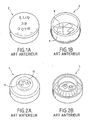
- This commercial seal is simple and inexpensive. It is composed of two capsules, one in copper and the other in brass.
- Figures 1A and 1B show the copper part 2 in external view (Figure 1A) and internal ( Figure 1B).
- Figures 2A and 2B show the brass part 4 in external view ( Figure 2A) and internal ( Figure 2B).
- the identity of this seal is obtained by means of a drop of tin 6 placed inside the capsules, then randomly scratched in order to obtain a single drawing.
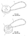
- One of the capsules, which is snapped on the other, in order to close the seal during its use contains 2 orifices 10, 12 making it possible to pass the two ends of a metallic wire, or non-metallic, multi-stranded or not , which will link together the elements that will have to be sealed. For example, in the case of the condemnation of a door or a cabinet, this wire goes into handles. The two ends of the wire are then tied together, inside the brass cap 4, and the seal is closed.
- FIGS. 3A and 3B view on the brass side.
- the seal is used, and its identity is controlled, as follows.
- the identity of the two capsules is photographed and stored numerically in a database. It is an archiving step. An identification number, engraved on the capsule containing the identity, is also archived as the number of the seal, correlated with the two identities.
- the identification number is correlated with data such as: date of installation, place ...
- Such a seal is of low cost, and its implementation is simple. However, its control presents a certain difficulty, as well as a high cost.
- the cost of such a seal, including the control of its identity, is of the order of 140 Euros.
- the identification technique is also not very easy: it is necessary in particular to photograph the identities and correlate them to the external number of the seal. All these long operations require manipulations that can be sources of errors.
- the document EP 0 825 554 A1 describes an electronic seal intended to be fixed on an object to be sealed.
- the seal includes an electrical circuit that is broken when the seal is broken.
- a seal comprising two capsules that can snap into each other and having attachment means for housing an electronic component in its interior is described in the international patent application WO 97/38193 .
- the document US5,008,661 describes an electronic remote identification and searchable system for chemicals transported by truck, train or other means of transport.
- the system comprises a transponder carrying information relating to the chemical substance, fixed on the means of transport, and a reader able to remotely read the information contained in the transponder.
- the invention aims to overcome these disadvantages.
- the invention is defined in the claims and in particular in the independent claims 1, 18 and 22.
- the invention seeks to solve these problems by proposing a seal, for connecting together elements to be sealed, comprising a first and second capsules to be sealed, as well as electronic means, to be disposed in at least one of the capsules, being able to contain a seal identification and remotely searchable.
- Closing means make it possible to close the two capsules together.
- the closure means comprise at least one male part situated at the periphery of one of the two capsules, and at least one female part located on the periphery of the other capsule, these two parts being adapted to snap into each other
- means make it possible to control whether the seal has been opened, or not, after closure.
- These means are preferably means of irreversible closure, or single use; their opening is impossible without destroying them or damaging them or marking them, at least partially.
- the seal can not be opened without destruction or without damage or marking, at least partially, closure means.
- the capsules are provided with mechanical indicators of rupture or deformation.
- the identities in tin, which are in the capsules, are replaced by electronic identities, or "codes", also placed inside the capsules.
- the identity of the seal can be read by active reading means.
- the electronic means are preferably passive, thus requiring no power device or battery, which reduces the size in the capsule where it is installed.
- the electronic means may be of the passive electronic transponder type, containing a digital code.
- plastic capsules improves efficiency and reading distance.
- a material having plastic deformation characteristics is used. Indeed, an attempt to open a seal made of such a material is most often translated by the deformation of one part or another of the seal, including its closure means. Such a deformation is easily visible on a material with plastic deformation, leaving at least one mark.
- a particularly suitable material is based on ABS, at least 25%.
- the information data can then be stored and / or transferred to a computer for storage and / or analysis.
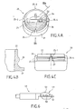
- Figures 4A-4C and 5A-5D show various views of two capsules 20, 30 of a seal according to the invention.
- the two capsules 20, 30 are of approximately cylindrical shape and include means for closing the seal during use. They are for example designed to fit with each other or to snap one on the other, and are then provided with a system, or means, snap or interlocking , or means for clipping together (closure clipping).
- the assembly In the closed position, the assembly is also sealed, and can not be opened without there being destruction or deformation or marking, at least partially, of the seal.
- Each capsule may have a location 24, 34 to introduce an electronic identification device 23, 33.
- a seal according to the invention may also operate with a single electronic identification device, in which case a single location is provided to mount a such a device, in only one of the two capsules.
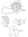
- the closure or latching means essentially comprise one or more tenons 25-1, 25-2, 25-3, 25-4 located on the periphery of the one of the capsules (FIG. 4A), and one or the corresponding mortise (s) 35-1, 35-2, 35-3, 35-4 located on the periphery of the other capsule ( Figure 5A).
- each stud 25 - i male part of the latching system
- a mortise 35 - i female part of the latching system
- One of the two caps 20 comprises for example a base 21 of approximately cylindrical shape, at one end of which the pins 25-1, 25-2, 25-3, 25-4 can be arranged.
- the same capsule may further comprise a ring 22 also substantially cylindrical shape, of outside diameter less than the outside diameter of the base 21.
- a rib 26 On the periphery of this ring 22, and therefore recessed relative to the outer surface of the base 21 and relative to the studs 25-1, 25-2 , 25-3, 25-4, is formed a rib 26 of approximately trapezoidal section.
- the other capsule 30 has a wall 31 also of approximately cylindrical shape. On the inner periphery of this wall is formed a groove 36 of approximately trapezoidal section, which corresponds to the rib 26 of the first capsule 20.
- the rib 26 may have another shape. It may be for example of approximately triangular section.
- the groove 36 then has a corresponding triangular shape in the example just given.
- a substantially cylindrical ring 38 may also be formed inside this capsule 30. As illustrated in FIG. 5B, this ring extends, in a direction parallel to the cylindrical axis of symmetry of the capsule, at least as far as 'at the height of the throat 36.
- the tenons are introduced into the mortises, and the ring 22 is inserted between the two cylindrical walls 31 and 38. By pressure, the tenons are completely inserted into the mortises. mortises, and the rib 26 is inserted into the groove 36.
- the tenons can only be removed from the mortise by forcing the latching system. It is the same for the rib 26 which can be extracted from the throat 36 only by forcing.
- the latching means of the device according to the invention and in particular the combination of the tenons and mortises, on the one hand, and the rib 26 and the groove 36, on the other hand, constitute breaking or deformation in the event of an attempt to open the seal. Such an attempt results in fact in marks, and / or scratches and / or breakage of the latching means, and therefore, in the mode of proposed embodiment, tenons, and / or mortises and / or rib and / or throat.
- each stud has the shape of a triangular point or arrow, with a narrowed base 27.
- the corresponding female or mortise part (FIG. 5D) has a triangular arrow or point shape corresponding, with lips 37 - 1 and 37 - 2 projecting, located at the base. These lips cooperate with the narrowed base 27 of the tenon so that the male part (pin) is introduced into the female part (mortise), without the possibility of being extracted, if not by force.
- FIG. 6 An electronic device that can be used in the seal according to the invention is shown in FIG. 6. It is a passive electronic transponder containing a numerical code.
- a transponder is a device that transmits the information it has in memory when activated by a transceiver. Possibly, it can store new information.
- a transponder can be of the HDX type (half duplex: the information is transmitted once the transceiver has stopped transmitting the activation field) or FDX (duplex: the information is transmitted during the period of time). activation by the transceiver).
- Transponders that can be used, and their method of interrogation, are described in International Standard ISO 11785: 1996 (F) and its Appendices.
- such a device comprises antenna means, comprising for example a portion 48 consisting of a ferrite core and a coil wound around this core, and an electronic portion 49, incorporating storage means 50 and a 51.
- Connecting son 52 connect the two parts 48, 49. An attempt to open the seal causes a rupture of these son or the ferrite, or the antenna coil, which is a means of monitoring additional seal. During a subsequent interrogation of the transponder, the malfunction of the device will be immediately noted.
- Such a transponder is for example described in the document EP480530 .
- An example of a passive transponder that can be used is a model of Texas Instruments (Tiris), injectable, 23 mm long and 3.8 mm in diameter. It is coated, without its glass tube, in one or each of the capsules 20, 30, which provides a certain mechanical integrity of the identifier.
- This transponder, "Half Duplex" (HDX) contains a unique code, programmed in the factory, of 64 bits. Due to the structure of the code used, 274,877,906,944 combinations of numerical codes are possible.
- transponder Tiris was chosen for the first prototypes.
- the seal according to the invention can be installed in the same manner as the seal of the prior art described above in connection with FIGS. 3A and 3B.
- Means are in particular provided for attaching the seal to an external device, inside the seal, or for connecting together elements to be sealed.
- Two orifices 32 may be provided for this purpose in one or other of the two capsules 20, 30.
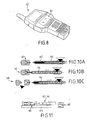
- a wire 40 may be tied inside the capsules, through the two orifices (Figure 5A, 7A). The seal can then be closed manually, by simple pressure (Figure 7B), the wire node being contained and sealed in the seal.
- the means for fixing the seal to an external device are such that the seal can not be detached without opening it, or without destroying, at least in part, these fastening means or their integrity (here: without cutting thread).
- the identity of the seal can be read for example by means of a portable reader 42 (FIG. 8).
- a portable reader 42 (FIG. 8).
- Such a reader may also comprise, for example, a display screen 44, and / or storage means of the interrogated data.
- the reader activates the radio frequency (RF) transponder, for example at a frequency of 134.2 kHz.
- RF radio frequency
- each interrogated transponder is thus returned to the reader 42, and displayed on its LCD screen 44, and / or stored in its memory, or transferred in real time, via a serial interface, to a laptop.
- Software may make it possible to correlate the seal identification number (the transponder code) with various data such as, for example, the location, and / or the name of the inspector who installed the seal, and / or the date.
- two portable readers are used.
- the first is a Diehl DHP 102 reader (electric field 104 dB ⁇ V / M at 3 meters), connected to a small computer "Palmtop" Psion Workabout.
- the second is a Gesimpex Gesreader IIS reader containing memory and software, and equipped with a keyboard for manual data entry, with the same frequency and the same electric field as the Diehl.
- the latter player is also equipped with an internal antenna and can receive an external stick antenna for particular uses.
- the transponders are activated (at a frequency of 134.2 kHz) using the radio frequency module that can be connected to the end of the "Palmtop".
- the system thus developed allows the identity of the seal to be read at a distance varying from contact up to 30 cm (depending on the reader used), which is sufficient for most uses.
- Each transponder has its own code, the two codes (C 1 , C 2 ) corresponding and corresponding to a single seal, identified for example by a number.
- a database collects information on the seal numbers, as well as the corresponding code pairs (C 1 , C 2 ). If a person opens the seal and replaces one of the transponders (for example that of code C 1 ), by another transponder of code C ' 1 , the new state (C' 1 , C 2 ) of the pair of codes does not will not match a code pair listed in the database. This results in finer monitoring of the seal.
- a seal comprising two transponders operates optimally when the two transponders, or their axes of maximum sensitivity, are arranged perpendicularly to one another.
- seals whose closing means are arranged asymmetrically on the capsules, or else in other words, which define a position of single closure of both capsules.
- Figure 4C shows an embodiment in which one of the studs 25 - 1 (shown in broken lines) is larger than the others.
- the corresponding female part, in the capsule 30, also has a larger size than that of the other female parts. Thus a single closed position is defined.
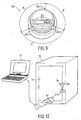
- FIG. 9 Another embodiment of a capsule 120 is shown in FIG. 9.
- Three tenons, 125-1, 125-2, 125-3, are arranged at an unequal distance from one another (the angles A and B are respectively 125 ° and 110 °), the three corresponding mortises being arranged in the same manner on the other capsule.
- a single closing position is defined.
- four tenons are arranged with different angles between them.
- the first and second tenons are separated by an angle A ', as are the second tenon and the third tenon, while the third and fourth tenon are separated by an angle B' ( ⁇ A ') and that the fourth and the first tenon are separated by an angle C '(C' ⁇ B 'and C' ⁇ A ').
- a ' 90 °
- B' 85 °
- C ' 95 °.
- the angles are chosen so that at least two or three of the four angles are different from each other.
- the seal according to the invention may be made of brass or copper, but it is preferably made of a plastic material, so that any attempt to open the seal results in marks on the material.
- a particularly suitable material is ABS (acrylonitrile-butadiene-styrene).
- ABS material also gives the seal according to the invention excellent reading efficiency, close to 100%, and greater than the effectiveness obtained with brass, copper or aluminum seals.
- ABS has plastic deformation characteristics. If it is deformed (which is the case when someone tries to break a seal according to the invention) traces of deformation remain. A seal made of such a material therefore has a high degree of security.
- thermoplastic material obtained by mixing polycarbonate (PC, Makrolon) and acrylonitrile-butadiene-styrene (ABS, Novodur), such as Bayblend ref. T85MN from BAYER.
- the Bayblend ref. T85MN has a softening point value of 8 (about 130 VST / B ° C) according to the vicat B index.
- the index 5 means that there is no modification of the product.
- the dimensional stability under heat of the PC - ABS mixture varies, depending on the exact composition, between 110 ° C and 134 ° C. It is therefore located between the corresponding values for the ABS and the PC.
- PC rigidity and hardness of a PC - ABS mixture (with at least 25% ABS, for example: 30% ABS and 70% PC) are conferred by the PC.
- Bayblend is distinguished by its high impact resistance and elongation properties without fracture.
- the PC - ABS blend and especially the Bayblend also has excellent electrical insulation properties.
- the volume resistivity is 10 12 ⁇ cm, the surface resistivity is 10 14 ⁇ cm and the breakdown resistance 24 kV / mm; they are very little influenced by temperature variations or humidity.
- the most important characteristics of this mixture are stability to thermo-deformation, toughness and rigidity.
- a seal made of thermoplastic material can be made by molding. The method involves injecting a melt of materials into a closed mold, which is then cooled. The plastic solidifies and can be extracted from the mold.
- FIGS. 10A to 10B schematically show steps of such a method.
- a mold 60 is closed.
- a plastic material is introduced into an injection cylinder 62, in the molten state. It is injected into the mold 60 by means of a screw 64.
- FIG. 11 schematically represents a device for implementing this method.
- the mold 60 and the injection device 62, 64 are mounted on a table 66.
- the assembly is controlled by a control unit 68.
- the electronic means can be fixed using a semi-rigid resin, without solvent.
- a resin based on polyacool, beaver oil and calcium carbonate catalyst: diphenylmethane diisocyanate.
- Such a resin is known as "Diapol 508". It is 100% polymerized and has low water absorption. It hardens at room temperature and has no chemical aggressiveness. Its dimensional stability is good and it offers great adhesion to metals and plastics.
- the device according to the invention which comprises electronic means that can be read or interrogated from outside the seal has the following advantages.
- the seal can be identified when immersed.
- the identity identified during a test can be easily stored, thanks to a simple computer link in series. Simple correlations can then be established between identities and inspection data. This results in a significant saving of time for reading identities, as well as a low cost of identification
- the system thus produced has a relatively low cost, since it can be produced at a price of about 14 to 20 Euros depending on the quantities produced.
- FIG. 1 An example of application of the invention is illustrated in FIG. 1
- a box 72 contains sealed materials, for example nuclear materials (Plutonium, Uranium ... etc.).
- the door 74 and the fixed part of the trunk are both pierced with a hole 76, 80.
- a device according to the invention seals the trunk, using a wire 40 which passes through the holes 76, 80.
- This device according to the invention contains, in at least one of the capsules, electronic identification means, remotely searchable.
- a reader 42 is approached, which interrogates the electronic identification means in the manner already described above.
- the coding information, returned to the reader 42 by the seal, can then be transmitted to a portable computer 70, where the data is stored, and with which they can then be analyzed.
- the data can also be stored and processed in the reader 42 itself, without the latter being connected to a laptop. The data collection is therefore simple and very fast.
- the example was given of a chest containing nuclear material.
- Other applications concern chests containing electrical equipment (for example: electricity meter) or gas meters, or foodstuffs which one wants to ensure that they will not be adulterated (for example oil ).
Landscapes
- Engineering & Computer Science (AREA)
- Computer Security & Cryptography (AREA)
- Physics & Mathematics (AREA)
- General Physics & Mathematics (AREA)
- Theoretical Computer Science (AREA)
- Burglar Alarm Systems (AREA)
- Radar Systems Or Details Thereof (AREA)
- Arrangements For Transmission Of Measured Signals (AREA)
- Measurement Of The Respiration, Hearing Ability, Form, And Blood Characteristics Of Living Organisms (AREA)
- Lock And Its Accessories (AREA)
- Sealing Material Composition (AREA)
- Details Of Rigid Or Semi-Rigid Containers (AREA)
- Warehouses Or Storage Devices (AREA)
- Image Input (AREA)
- Devices For Checking Fares Or Tickets At Control Points (AREA)
Claims (25)
- Zu versiegelndes System, bestehend aus:- einer ersten Kapsel (20),- einer zweiten Kapsel (30),- elektronischen Mitteln (23, 33), die in mindestens einer der Kapseln angeordnet werden, eine elektronische Identifikation enthalten können und aus der Ferne abfragbar sind,- Schließmitteln (25-1, 25-2, 25-3, 25-4; 35-1, 35-2, 35-3, 35-4) zum Versiegeln der beiden Kapseln,dadurch gekennzeichnet, dass die Schließmittel aus mindestens einem, am Umfang einer der beiden Kapseln liegenden Vaterteil und mindestens einem, am Umfang der anderen Kapsel liegenden Mutterteil bestehen, wobei diese beiden Teile so ausgelegt sind, dass sie ineinander einrasten.
- System nach Anspruch 1, wobei die Kapseln mit Bruch- oder Verformungsanzeigern versehen sind.
- System nach Anspruch 1 oder 2, wobei die Vaterteile (25-1, 25-2, 25-3, 25-4) und Mutterteile (35-1, 35-2, 35-3, 35-4) so zusammenwirken, dass eine Verbindung hergestellt wird, die nur mit Gewalt geöffnet werden kann.
- System nach einem der Ansprüche 1 bis 3, wobei die Schließmittel aus mindestens einer Schlitz-Zapfen-Verbindung bestehen.
- System nach einem der Ansprüche 1 bis 4, wobei die beiden Kapseln im Wesentlichen zylindrisch ausgestaltet sind, wobei eine der Kapseln (20) eine Rippe (26) aufweist, die mit einer auf einer Innenfläche der anderen Kapsel (30) ausgebildeten Nut (36) zusammenwirkt.
- System nach einem der Ansprüche 1 bis 5, wobei die Schließmittel der beiden Kapseln eine einzige Schließstellung definieren.
- System nach Anspruch 6, wobei die Schließmittel um die beiden Kapseln herum getrennt sind und untereinander Winkel bilden, von denen mindestens zwei verschieden sind.
- System nach einem der Ansprüche 1 bis 7, wobei die elektronischen Mittel (23, 33) passive elektronische Mittel sind.
- System nach einem der Ansprüche 1 bis 8, wobei die elektronischen Mittel (23, 33) programmierbare elektronische Mittel sind.
- System nach einem der Ansprüche 1 bis 9, wobei die elektronischen Mittel (22, 23) mindestens einen passiven elektronischen Transponder umfassen, der numerisch codiert werden kann.
- System nach Anspruch 10, welches zwei passive elektronische Transponder aufweist, die numerisch codiert werden können.
- System nach einem der Ansprüche 1 bis 11, wobei die elektronischen Mittel (23, 33) einen oder mehrere Drähte (52) aufweisen, die sich beim Öffnen des Systems nach dessen Schließen brechen lassen.
- System nach einem der Ansprüche 1 bis 12, welches außerdem Mittel (32) aufweist, mit denen eine Befestigung des Systems an einer außen liegenden Vorrichtung durchgeführt werden kann.
- System nach Anspruch 13, welches außerdem Mittel (40) zur Befestigung an einer außen liegenden Vorrichtung aufweist.
- System nach einem der Ansprüche 1 bis 14, wobei die Kapseln (20, 30) aus Kunststoff sind.
- System nach einem der Ansprüche 1 bis 15, wobei die Kapseln (20, 30) aus einem Werkstoff bestehen, der plastische Verformungseigenschaften aufweist.
- System nach Anspruch 16, wobei der Werkstoff ABS mit einem Anteil von mindestens 25 % enthält.
- Siegelsystem, gebildet aus einem zu versiegelnden System nach irgendeinem der Ansprüche 1 bis 17, bei dem die elektronischen Mittel (23, 33) in mindestens einer der Kapseln angeordnet sind, eine elektronische Identifikation enthalten und von außerhalb des Siegelsystems abfragbar sind, wobei das Siegelsystem
dadurch gekennzeichnet ist, dass die beiden Kapseln durch mindestens ein, am Umfang einer der beiden Kapseln liegendes Vaterteil und mindestens ein, am Umfang der anderen Kapsel liegendes Mutterteil versiegelt sind, wobei diese Teile ineinander eingerastet sind. - Siegelsystem nach Anspruch 18, wobei die elektronischen Mittel (23, 33) aus mindestens einem passiven elektronischen Transponder bestehen.
- System nach Anspruch 19, welches einen passiven elektronischen Transponder in jeder der Kapseln aufweist.
- System nach Anspruch 20, wobei die Achsen der Transponder in einem Winkel von 90° zueinander angeordnet sind.
- Verfahren zur Kontrolle eines Siegelsystems nach einem der Ansprüche 18 bis 21, bei dem eine Leseeinrichtung (42) an das Siegelsystem herangeführt wird, eine Welle in Richtung des Systems ausgesendet wird und eine von dem System ausgesendete Welle empfangen wird, welche die Information über die elektronische Identifikation enthält.
- Verfahren nach Anspruch 22, wobei die Leseeinrichtung Speicherungsmittel aufweist, sowie Mittel zur manuellen Eingabe von Daten.
- Verfahren nach Anspruch 22 oder 23, wobei die Daten über die elektronische ldentifikationsinformation an einen Rechner (70) übertragen werden.
- Verfahren nach einem der Ansprüche 22 bis 24, wobei das Siegelsystem an einem Container (72) angebracht wird, der Kernmaterial enthält, oder Elektromaterial oder Lebensmittel.
Priority Applications (12)
| Application Number | Priority Date | Filing Date | Title |
|---|---|---|---|
| DE69937794T DE69937794T2 (de) | 1999-09-15 | 1999-09-15 | Elektronisches Mehrwegsiegel mit passivem Transponder |
| EP99402256A EP1087334B1 (de) | 1999-09-15 | 1999-09-15 | Mehrwegelektronisches Siegel mittels eines passiven Transponders |
| DK99402256T DK1087334T3 (da) | 1999-09-15 | 1999-09-15 | Elektronisk segl med passiv transponder og til forskellige anvendelser |
| PT99402256T PT1087334E (pt) | 1999-09-15 | 1999-09-15 | Selo multiuso electrónico de transpondedor passivo |
| AT99402256T ATE381743T1 (de) | 1999-09-15 | 1999-09-15 | Mehrwegelektronisches siegel mittels eines passiven transponders |
| ES99402256T ES2297915T3 (es) | 1999-09-15 | 1999-09-15 | Precinto multiuso electronico con transpondedor pasivo. |
| CA002384673A CA2384673C (en) | 1999-09-15 | 2000-09-15 | Electronic multipurpose seal with passive transponder |
| US10/070,414 US6888241B1 (en) | 1999-09-15 | 2000-09-15 | Electronic multipurpose seal with passive transponder |
| JP2001524050A JP2003509311A (ja) | 1999-09-15 | 2000-09-15 | 受動的トランスポンダーを有する電子多目的シール |
| PCT/EP2000/009113 WO2001020543A1 (fr) | 1999-09-15 | 2000-09-15 | Scelle multi-usage electronique a transpondeur passif |
| NO20021276A NO334874B1 (no) | 1999-09-15 | 2002-03-14 | Elektronisk flerbruksforsegling med passiv transponder |
| CY20081100239T CY1107292T1 (el) | 1999-09-15 | 2008-02-29 | Ηλεκτρονικη σφραγιση χρησης με παθητικο πομποδεκτη |
Applications Claiming Priority (1)
| Application Number | Priority Date | Filing Date | Title |
|---|---|---|---|
| EP99402256A EP1087334B1 (de) | 1999-09-15 | 1999-09-15 | Mehrwegelektronisches Siegel mittels eines passiven Transponders |
Publications (2)
| Publication Number | Publication Date |
|---|---|
| EP1087334A1 EP1087334A1 (de) | 2001-03-28 |
| EP1087334B1 true EP1087334B1 (de) | 2007-12-19 |
Family
ID=8242112
Family Applications (1)
| Application Number | Title | Priority Date | Filing Date |
|---|---|---|---|
| EP99402256A Expired - Lifetime EP1087334B1 (de) | 1999-09-15 | 1999-09-15 | Mehrwegelektronisches Siegel mittels eines passiven Transponders |
Country Status (12)
| Country | Link |
|---|---|
| US (1) | US6888241B1 (de) |
| EP (1) | EP1087334B1 (de) |
| JP (1) | JP2003509311A (de) |
| AT (1) | ATE381743T1 (de) |
| CA (1) | CA2384673C (de) |
| CY (1) | CY1107292T1 (de) |
| DE (1) | DE69937794T2 (de) |
| DK (1) | DK1087334T3 (de) |
| ES (1) | ES2297915T3 (de) |
| NO (1) | NO334874B1 (de) |
| PT (1) | PT1087334E (de) |
| WO (1) | WO2001020543A1 (de) |
Families Citing this family (28)
| Publication number | Priority date | Publication date | Assignee | Title |
|---|---|---|---|---|
| EP1450300A1 (de) * | 2003-02-24 | 2004-08-25 | European Community | Vorrichtung zur Versiegelung mit mehreren Transpondern |
| US7270353B2 (en) | 2003-02-24 | 2007-09-18 | The European Community | Multiple transponder seal device |
| JP4190934B2 (ja) * | 2003-04-10 | 2008-12-03 | 株式会社デンソー | 携帯型送信機 |
| US7639134B2 (en) * | 2003-05-07 | 2009-12-29 | Savi Technology, Inc. | Item-level visibility of nested and adjacent containers |
| US20050162269A1 (en) * | 2003-05-07 | 2005-07-28 | Lambright Stephen J. | Dual mode reader device |
| DE20313078U1 (de) * | 2003-08-23 | 2004-12-30 | Wincor Nixdorf International Gmbh | Verschluss für ein Aufbewahrungsbehältnis |
| US7358856B2 (en) * | 2004-03-18 | 2008-04-15 | Savi Technology, Inc. | Two-phase commit synchronizing seal state |
| US7755486B2 (en) * | 2004-05-06 | 2010-07-13 | Savi Technology, Inc. | Expanded compatibility RFID tags |
| FR2877472B1 (fr) * | 2004-11-04 | 2008-06-06 | Novatec Sa Sa Soc | Procede et dispositif de verification de non intrusion dans un systeme et/ou de non atteinte a l'integrite d'un objet |
| NZ534456A (en) * | 2005-01-29 | 2007-09-28 | Pallenz Plastics Ltd | Protective housing for wireless identification tag with coupling means releasably coupled and at least partially surrounded by portable storage device (typically a pallet) |
| FR2893595B1 (fr) | 2005-11-23 | 2010-08-27 | Novatec Sa Soc | Scelle de haute securite inviolable et reutilisable |
| US7740292B1 (en) * | 2006-09-22 | 2010-06-22 | Fattori Lazzaro A | Mechanical tamper-evident high security seal and method of use to secure a cargo container |
| US20080180242A1 (en) * | 2007-01-29 | 2008-07-31 | Cottingham Hugh V | Micron-scale implantable transponder |
| US20080309645A1 (en) * | 2007-06-15 | 2008-12-18 | Cheng Uei Precision Industry Co., Ltd. | Mobile electronic device |
| USD600151S1 (en) * | 2008-01-23 | 2009-09-15 | Maritime It As | Retainer for electronic identification tag |
| US8186731B1 (en) * | 2009-04-14 | 2012-05-29 | Sandia Corporation | Tamper indicating seal |
| USD617668S1 (en) * | 2009-05-17 | 2010-06-15 | Exaqtworld | Anti-theft device |
| US8308073B2 (en) * | 2010-06-15 | 2012-11-13 | Convergence Systems Limited | Radio frequency identification (RFID) tag |
| US9892618B2 (en) * | 2013-08-09 | 2018-02-13 | Mobile Aspects, Inc. | Signal emitting member attachment system and arrangement |
| US10679523B2 (en) | 2016-07-26 | 2020-06-09 | Savannah River Nuclear Solutions, Llc | Tamper indicating seal |
| DE102017107705A1 (de) * | 2017-04-10 | 2018-10-11 | Gemü Gebr. Müller Apparatebau Gmbh & Co. Kommanditgesellschaft | Vorrichtung zur Anordnung eines elektronischen Datenträgers an einer Komponente einer fluidtechnischen Anlage |
| US10597903B2 (en) * | 2018-04-27 | 2020-03-24 | Andrew C. Reeves | Systems and methods of securing items and verifying the same |
| WO2020160295A1 (en) | 2019-01-30 | 2020-08-06 | Montelino Therapeutics, Llc | Bi-functional compounds and methods for targeted ubiquitination of androgen receptor |
| FR3108422B1 (fr) * | 2020-03-18 | 2022-07-01 | Pa Cotte Sa | Colis comprenant un scellé radio-identifié |
| US11981672B2 (en) | 2021-09-13 | 2024-05-14 | Montelino Therapeutics Inc. | Bi-functional compounds and methods for targeted ubiquitination of androgen receptor |
| US12486697B2 (en) * | 2023-05-04 | 2025-12-02 | Shenzhen Wins Electronic Technology Co., Ltd. | Cable lock with locator |
| CN220434483U (zh) * | 2023-05-04 | 2024-02-02 | 深圳市双盈运动科技有限公司 | 用于金属丝标签锁的定位装置 |
| US20240400276A1 (en) * | 2023-06-02 | 2024-12-05 | The Boeing Company | Systems and methods for indicating tampering of a container |
Citations (1)
| Publication number | Priority date | Publication date | Assignee | Title |
|---|---|---|---|---|
| US5008661A (en) * | 1985-09-27 | 1991-04-16 | Raj Phani K | Electronic remote chemical identification system |
Family Cites Families (13)
| Publication number | Priority date | Publication date | Assignee | Title |
|---|---|---|---|---|
| US1977301A (en) | 1932-12-16 | 1934-10-16 | Andrew O Bradford | Seal |
| US1997301A (en) | 1933-06-20 | 1935-04-09 | Meta A Kniffen | Feed mixer |
| JPS4124310Y1 (de) * | 1964-10-27 | 1966-12-10 | ||
| JPS4125349Y1 (de) * | 1964-11-20 | 1966-12-26 | ||
| US4523186A (en) * | 1982-08-12 | 1985-06-11 | The United States Of America As Represented By The United States Department Of Energy | Seal system with integral detector |
| CH656582A5 (en) * | 1983-02-10 | 1986-07-15 | Soplex Societe De Personnes A | Security seal |
| US4727668A (en) * | 1985-09-03 | 1988-03-01 | Allied Corporation | Coded surveillance marker with improved biasing |
| EP0608250B1 (de) * | 1991-09-13 | 1996-05-15 | Rodney Arthur Stafford | Elektronisches identifizierungssystem für tieren |
| GB9607553D0 (en) * | 1996-04-11 | 1996-06-12 | Scafftag Limited | Improvements relating to security containers |
| EP0825554A1 (de) * | 1996-08-13 | 1998-02-25 | Fyrtech Microelectronics AB | Versiegelungsvorrichtung |
| US5984875A (en) * | 1997-08-22 | 1999-11-16 | Innotek Pet Products, Inc. | Ingestible animal temperature sensor |
| US5986562A (en) * | 1998-09-11 | 1999-11-16 | Brady Worldwide, Inc. | RFID tag holder for non-RFID tag |
| AU5924599A (en) * | 1998-09-11 | 2000-04-03 | Key-Trak, Inc. | Tamper detection and prevention for an object control and tracking system |
-
1999
- 1999-09-15 AT AT99402256T patent/ATE381743T1/de active
- 1999-09-15 PT PT99402256T patent/PT1087334E/pt unknown
- 1999-09-15 ES ES99402256T patent/ES2297915T3/es not_active Expired - Lifetime
- 1999-09-15 EP EP99402256A patent/EP1087334B1/de not_active Expired - Lifetime
- 1999-09-15 DK DK99402256T patent/DK1087334T3/da active
- 1999-09-15 DE DE69937794T patent/DE69937794T2/de not_active Expired - Lifetime
-
2000
- 2000-09-15 JP JP2001524050A patent/JP2003509311A/ja active Pending
- 2000-09-15 WO PCT/EP2000/009113 patent/WO2001020543A1/fr not_active Ceased
- 2000-09-15 CA CA002384673A patent/CA2384673C/en not_active Expired - Fee Related
- 2000-09-15 US US10/070,414 patent/US6888241B1/en not_active Expired - Fee Related
-
2002
- 2002-03-14 NO NO20021276A patent/NO334874B1/no not_active IP Right Cessation
-
2008
- 2008-02-29 CY CY20081100239T patent/CY1107292T1/el unknown
Patent Citations (1)
| Publication number | Priority date | Publication date | Assignee | Title |
|---|---|---|---|---|
| US5008661A (en) * | 1985-09-27 | 1991-04-16 | Raj Phani K | Electronic remote chemical identification system |
Also Published As
| Publication number | Publication date |
|---|---|
| ATE381743T1 (de) | 2008-01-15 |
| DK1087334T3 (da) | 2008-04-07 |
| NO20021276L (no) | 2002-05-14 |
| CA2384673C (en) | 2008-07-08 |
| ES2297915T3 (es) | 2008-05-01 |
| CY1107292T1 (el) | 2012-11-21 |
| DE69937794D1 (de) | 2008-01-31 |
| NO20021276D0 (no) | 2002-03-14 |
| PT1087334E (pt) | 2008-03-10 |
| CA2384673A1 (en) | 2001-03-22 |
| NO334874B1 (no) | 2014-06-23 |
| US6888241B1 (en) | 2005-05-03 |
| DE69937794T2 (de) | 2009-04-30 |
| EP1087334A1 (de) | 2001-03-28 |
| WO2001020543A1 (fr) | 2001-03-22 |
| JP2003509311A (ja) | 2003-03-11 |
Similar Documents
| Publication | Publication Date | Title |
|---|---|---|
| EP1087334A1 (de) | Mehrwegelektronisches Siegel mittels eines passiven Transponders | |
| EP2794199B1 (de) | Einrichtung mit einem handschuhfach und handschuhwechselvorrichtung mit überwachung des handschuhwechsels | |
| US9836633B2 (en) | Dendritic structures and tags | |
| EP1511909B9 (de) | Mehrzwecksiegel mit einem schloss und verfahren zur herstellung eines mehrzwecksiegels | |
| US8040244B2 (en) | Closure with passive electronic sensor for tamper detection and related method | |
| US20110031139A1 (en) | Protection, authentication, identification device for a physical object specimen | |
| EP3213264B1 (de) | Verfahren zur authentifizierung des verschlusses eines behälters | |
| CN108368710B (zh) | 具有防篡改传感器和网络安全的安全系统 | |
| WO2021185677A1 (fr) | Colis comprenant un scellé radio-identifié | |
| WO2004040151A1 (fr) | Organe de fixation à intégrité contrôlable | |
| US20210157888A1 (en) | Secure access with dendritic identifiers | |
| WO2020165242A1 (en) | Tamper evident rfid based system and method | |
| CA2516844C (fr) | Dispositif de scelle a transpondeur multiple | |
| EP4121919B1 (de) | System zur lieferung eines objekts unter verwendung eines primären pakets zur identifizierung des objekts und anzeige eines dem identifizierten objekt entsprechenden etiketts auf dem primären paket | |
| US10553133B2 (en) | Apparatus and method for monitoring the manipulation of a transportable object | |
| EP4451184A1 (de) | Verfahren zur verwaltung eines handschuhs | |
| EP0214889A1 (de) | Vorrichtung und Verfahren zum Registrieren von Daten deren Echtheit gesichert werden muss | |
| FR3044578A1 (fr) | Procede d'integration d'une puce de radio-identification dans une structure et porte-filtre | |
| FR2952621A1 (fr) | Conteneur et systeme de protection d'objets | |
| EP1924962A1 (de) | Vorrichtung zum einkapseln einer mehrzahl von elektronischen identifizierungsetiketten | |
| FR2952622A1 (fr) | Procede et systeme de protection d'objets | |
| FR3028847A1 (fr) | Dispositif de protection du contenu d'un contenant et procede pour l'utilisation d'un tel sceau |
Legal Events
| Date | Code | Title | Description |
|---|---|---|---|
| PUAI | Public reference made under article 153(3) epc to a published international application that has entered the european phase |
Free format text: ORIGINAL CODE: 0009012 |
|
| AK | Designated contracting states |
Kind code of ref document: A1 Designated state(s): AT BE CH CY DE DK ES FI FR GB GR IE IT LI LU MC NL PT SE |
|
| AX | Request for extension of the european patent |
Free format text: AL;LT;LV;MK;RO;SI |
|
| 17P | Request for examination filed |
Effective date: 20010910 |
|
| AKX | Designation fees paid |
Free format text: AT BE CH CY DE DK ES FI FR GB GR IE IT LI LU MC NL PT SE |
|
| RAP1 | Party data changed (applicant data changed or rights of an application transferred) |
Owner name: EUROPEAN COMMUNITY |
|
| 17Q | First examination report despatched |
Effective date: 20060428 |
|
| GRAP | Despatch of communication of intention to grant a patent |
Free format text: ORIGINAL CODE: EPIDOSNIGR1 |
|
| GRAS | Grant fee paid |
Free format text: ORIGINAL CODE: EPIDOSNIGR3 |
|
| GRAA | (expected) grant |
Free format text: ORIGINAL CODE: 0009210 |
|
| AK | Designated contracting states |
Kind code of ref document: B1 Designated state(s): AT BE CH CY DE DK ES FI FR GB GR IE IT LI LU MC NL PT SE |
|
| REG | Reference to a national code |
Ref country code: GB Ref legal event code: FG4D Free format text: NOT ENGLISH |
|
| REG | Reference to a national code |
Ref country code: IE Ref legal event code: FG4D Free format text: LANGUAGE OF EP DOCUMENT: FRENCH |
|
| REG | Reference to a national code |
Ref country code: CH Ref legal event code: EP |
|
| REF | Corresponds to: |
Ref document number: 69937794 Country of ref document: DE Date of ref document: 20080131 Kind code of ref document: P |
|
| GBT | Gb: translation of ep patent filed (gb section 77(6)(a)/1977) |
Effective date: 20080206 |
|
| REG | Reference to a national code |
Ref country code: CH Ref legal event code: NV Representative=s name: WILLIAM BLANC & CIE CONSEILS EN PROPRIETE INDUSTRI |
|
| REG | Reference to a national code |
Ref country code: PT Ref legal event code: SC4A Free format text: AVAILABILITY OF NATIONAL TRANSLATION Effective date: 20080228 |
|
| REG | Reference to a national code |
Ref country code: GR Ref legal event code: EP Ref document number: 20080400583 Country of ref document: GR |
|
| REG | Reference to a national code |
Ref country code: SE Ref legal event code: TRGR |
|
| REG | Reference to a national code |
Ref country code: DK Ref legal event code: T3 |
|
| REG | Reference to a national code |
Ref country code: ES Ref legal event code: FG2A Ref document number: 2297915 Country of ref document: ES Kind code of ref document: T3 |
|
| PLBE | No opposition filed within time limit |
Free format text: ORIGINAL CODE: 0009261 |
|
| STAA | Information on the status of an ep patent application or granted ep patent |
Free format text: STATUS: NO OPPOSITION FILED WITHIN TIME LIMIT |
|
| 26N | No opposition filed |
Effective date: 20080922 |
|
| PG25 | Lapsed in a contracting state [announced via postgrant information from national office to epo] |
Ref country code: MC Free format text: LAPSE BECAUSE OF NON-PAYMENT OF DUE FEES Effective date: 20080930 |
|
| REG | Reference to a national code |
Ref country code: CH Ref legal event code: PFA Owner name: EUROPEAN COMMUNITY Free format text: EUROPEAN COMMUNITY# #1049 BRUSSELS (BE) -TRANSFER TO- EUROPEAN COMMUNITY# #1049 BRUSSELS (BE) |
|
| REG | Reference to a national code |
Ref country code: FR Ref legal event code: CD |
|
| REG | Reference to a national code |
Ref country code: DE Ref legal event code: R081 Ref document number: 69937794 Country of ref document: DE Owner name: EUROPEAN UNION, BE Free format text: FORMER OWNER: EUROPEAN COMMUNITY, BRUSSELS, BE Effective date: 20110208 |
|
| REG | Reference to a national code |
Ref country code: CH Ref legal event code: PCAR Free format text: NOVAGRAAF SWITZERLAND SA;CHEMIN DE L'ECHO 3;1213 ONEX (CH) |
|
| REG | Reference to a national code |
Ref country code: FR Ref legal event code: PLFP Year of fee payment: 17 |
|
| PGFP | Annual fee paid to national office [announced via postgrant information from national office to epo] |
Ref country code: NL Payment date: 20150820 Year of fee payment: 17 Ref country code: LU Payment date: 20150824 Year of fee payment: 17 |
|
| PGFP | Annual fee paid to national office [announced via postgrant information from national office to epo] |
Ref country code: DK Payment date: 20150821 Year of fee payment: 17 Ref country code: DE Payment date: 20150820 Year of fee payment: 17 Ref country code: PT Payment date: 20150908 Year of fee payment: 17 Ref country code: ES Payment date: 20150914 Year of fee payment: 17 Ref country code: CH Payment date: 20150824 Year of fee payment: 17 Ref country code: FI Payment date: 20150821 Year of fee payment: 17 Ref country code: GB Payment date: 20150825 Year of fee payment: 17 Ref country code: IE Payment date: 20150824 Year of fee payment: 17 |
|
| PGFP | Annual fee paid to national office [announced via postgrant information from national office to epo] |
Ref country code: AT Payment date: 20150821 Year of fee payment: 17 Ref country code: BE Payment date: 20150821 Year of fee payment: 17 Ref country code: FR Payment date: 20150824 Year of fee payment: 17 Ref country code: GR Payment date: 20150824 Year of fee payment: 17 Ref country code: SE Payment date: 20150820 Year of fee payment: 17 |
|
| PGFP | Annual fee paid to national office [announced via postgrant information from national office to epo] |
Ref country code: IT Payment date: 20150828 Year of fee payment: 17 |
|
| PGFP | Annual fee paid to national office [announced via postgrant information from national office to epo] |
Ref country code: CY Payment date: 20150820 Year of fee payment: 17 |
|
| PG25 | Lapsed in a contracting state [announced via postgrant information from national office to epo] |
Ref country code: BE Free format text: LAPSE BECAUSE OF NON-PAYMENT OF DUE FEES Effective date: 20160930 |
|
| REG | Reference to a national code |
Ref country code: DE Ref legal event code: R119 Ref document number: 69937794 Country of ref document: DE |
|
| REG | Reference to a national code |
Ref country code: DK Ref legal event code: EBP Effective date: 20160930 |
|
| PG25 | Lapsed in a contracting state [announced via postgrant information from national office to epo] |
Ref country code: FI Free format text: LAPSE BECAUSE OF NON-PAYMENT OF DUE FEES Effective date: 20160915 Ref country code: SE Free format text: LAPSE BECAUSE OF NON-PAYMENT OF DUE FEES Effective date: 20160916 |
|
| REG | Reference to a national code |
Ref country code: CH Ref legal event code: PL |
|
| REG | Reference to a national code |
Ref country code: SE Ref legal event code: EUG |
|
| REG | Reference to a national code |
Ref country code: NL Ref legal event code: MM Effective date: 20161001 |
|
| REG | Reference to a national code |
Ref country code: AT Ref legal event code: MM01 Ref document number: 381743 Country of ref document: AT Kind code of ref document: T Effective date: 20160915 |
|
| GBPC | Gb: european patent ceased through non-payment of renewal fee |
Effective date: 20160915 |
|
| PG25 | Lapsed in a contracting state [announced via postgrant information from national office to epo] |
Ref country code: CY Free format text: LAPSE BECAUSE OF NON-PAYMENT OF DUE FEES Effective date: 20160915 Ref country code: PT Free format text: LAPSE BECAUSE OF NON-PAYMENT OF DUE FEES Effective date: 20170315 |
|
| REG | Reference to a national code |
Ref country code: IE Ref legal event code: MM4A |
|
| PG25 | Lapsed in a contracting state [announced via postgrant information from national office to epo] |
Ref country code: NL Free format text: LAPSE BECAUSE OF NON-PAYMENT OF DUE FEES Effective date: 20161001 |
|
| REG | Reference to a national code |
Ref country code: FR Ref legal event code: ST Effective date: 20170531 |
|
| REG | Reference to a national code |
Ref country code: GR Ref legal event code: ML Ref document number: 20080400583 Country of ref document: GR Effective date: 20170411 |
|
| PG25 | Lapsed in a contracting state [announced via postgrant information from national office to epo] |
Ref country code: FR Free format text: LAPSE BECAUSE OF NON-PAYMENT OF DUE FEES Effective date: 20160930 Ref country code: GB Free format text: LAPSE BECAUSE OF NON-PAYMENT OF DUE FEES Effective date: 20160915 Ref country code: DE Free format text: LAPSE BECAUSE OF NON-PAYMENT OF DUE FEES Effective date: 20170401 Ref country code: GR Free format text: LAPSE BECAUSE OF NON-PAYMENT OF DUE FEES Effective date: 20170411 Ref country code: CH Free format text: LAPSE BECAUSE OF NON-PAYMENT OF DUE FEES Effective date: 20160930 Ref country code: IE Free format text: LAPSE BECAUSE OF NON-PAYMENT OF DUE FEES Effective date: 20160915 Ref country code: LI Free format text: LAPSE BECAUSE OF NON-PAYMENT OF DUE FEES Effective date: 20160930 |
|
| PG25 | Lapsed in a contracting state [announced via postgrant information from national office to epo] |
Ref country code: AT Free format text: LAPSE BECAUSE OF NON-PAYMENT OF DUE FEES Effective date: 20160915 Ref country code: IT Free format text: LAPSE BECAUSE OF NON-PAYMENT OF DUE FEES Effective date: 20160915 Ref country code: LU Free format text: LAPSE BECAUSE OF NON-PAYMENT OF DUE FEES Effective date: 20160915 |
|
| REG | Reference to a national code |
Ref country code: BE Ref legal event code: MM Effective date: 20160930 |
|
| PG25 | Lapsed in a contracting state [announced via postgrant information from national office to epo] |
Ref country code: DK Free format text: LAPSE BECAUSE OF NON-PAYMENT OF DUE FEES Effective date: 20160930 |
|
| PG25 | Lapsed in a contracting state [announced via postgrant information from national office to epo] |
Ref country code: ES Free format text: LAPSE BECAUSE OF NON-PAYMENT OF DUE FEES Effective date: 20160916 |
|
| REG | Reference to a national code |
Ref country code: ES Ref legal event code: FD2A Effective date: 20180627 |