EP1087367A1 - Méthode et dispositif pour le traitement de données d'exécution au moyen d'icônes représentant des symboles musicaux - Google Patents
Méthode et dispositif pour le traitement de données d'exécution au moyen d'icônes représentant des symboles musicaux Download PDFInfo
- Publication number
- EP1087367A1 EP1087367A1 EP00120484A EP00120484A EP1087367A1 EP 1087367 A1 EP1087367 A1 EP 1087367A1 EP 00120484 A EP00120484 A EP 00120484A EP 00120484 A EP00120484 A EP 00120484A EP 1087367 A1 EP1087367 A1 EP 1087367A1
- Authority
- EP
- European Patent Office
- Prior art keywords
- data
- performance data
- execution
- conversion
- midi
- Prior art date
- Legal status (The legal status is an assumption and is not a legal conclusion. Google has not performed a legal analysis and makes no representation as to the accuracy of the status listed.)
- Withdrawn
Links
- 238000000034 method Methods 0.000 title claims description 52
- 238000006243 chemical reaction Methods 0.000 claims abstract description 223
- 238000001914 filtration Methods 0.000 claims description 16
- 239000003086 colorant Substances 0.000 claims 1
- 239000000284 extract Substances 0.000 abstract description 6
- 230000006870 function Effects 0.000 description 23
- 238000010586 diagram Methods 0.000 description 11
- 230000004044 response Effects 0.000 description 11
- 238000013213 extrapolation Methods 0.000 description 9
- 238000012545 processing Methods 0.000 description 7
- 238000004364 calculation method Methods 0.000 description 6
- 238000000605 extraction Methods 0.000 description 6
- 230000014509 gene expression Effects 0.000 description 6
- 230000000694 effects Effects 0.000 description 5
- 238000004891 communication Methods 0.000 description 3
- 238000001514 detection method Methods 0.000 description 3
- 238000003379 elimination reaction Methods 0.000 description 3
- 230000002459 sustained effect Effects 0.000 description 3
- 238000013075 data extraction Methods 0.000 description 2
- 238000012217 deletion Methods 0.000 description 2
- 230000037430 deletion Effects 0.000 description 2
- 230000008030 elimination Effects 0.000 description 2
- 244000118350 Andrographis paniculata Species 0.000 description 1
- 230000003213 activating effect Effects 0.000 description 1
- 239000012190 activator Substances 0.000 description 1
- 238000004458 analytical method Methods 0.000 description 1
- ZYXYTGQFPZEUFX-UHFFFAOYSA-N benzpyrimoxan Chemical compound O1C(OCCC1)C=1C(=NC=NC=1)OCC1=CC=C(C=C1)C(F)(F)F ZYXYTGQFPZEUFX-UHFFFAOYSA-N 0.000 description 1
- 238000012937 correction Methods 0.000 description 1
- 230000001934 delay Effects 0.000 description 1
- 238000013461 design Methods 0.000 description 1
- 230000012447 hatching Effects 0.000 description 1
- 238000004519 manufacturing process Methods 0.000 description 1
- 239000000203 mixture Substances 0.000 description 1
- 238000009527 percussion Methods 0.000 description 1
- 239000007787 solid Substances 0.000 description 1
- 230000000007 visual effect Effects 0.000 description 1
Images





Classifications
-
- G—PHYSICS
- G10—MUSICAL INSTRUMENTS; ACOUSTICS
- G10H—ELECTROPHONIC MUSICAL INSTRUMENTS; INSTRUMENTS IN WHICH THE TONES ARE GENERATED BY ELECTROMECHANICAL MEANS OR ELECTRONIC GENERATORS, OR IN WHICH THE TONES ARE SYNTHESISED FROM A DATA STORE
- G10H1/00—Details of electrophonic musical instruments
- G10H1/0033—Recording/reproducing or transmission of music for electrophonic musical instruments
- G10H1/0041—Recording/reproducing or transmission of music for electrophonic musical instruments in coded form
- G10H1/0058—Transmission between separate instruments or between individual components of a musical system
- G10H1/0066—Transmission between separate instruments or between individual components of a musical system using a MIDI interface
-
- G—PHYSICS
- G10—MUSICAL INSTRUMENTS; ACOUSTICS
- G10H—ELECTROPHONIC MUSICAL INSTRUMENTS; INSTRUMENTS IN WHICH THE TONES ARE GENERATED BY ELECTROMECHANICAL MEANS OR ELECTRONIC GENERATORS, OR IN WHICH THE TONES ARE SYNTHESISED FROM A DATA STORE
- G10H1/00—Details of electrophonic musical instruments
- G10H1/0008—Associated control or indicating means
-
- G—PHYSICS
- G10—MUSICAL INSTRUMENTS; ACOUSTICS
- G10H—ELECTROPHONIC MUSICAL INSTRUMENTS; INSTRUMENTS IN WHICH THE TONES ARE GENERATED BY ELECTROMECHANICAL MEANS OR ELECTRONIC GENERATORS, OR IN WHICH THE TONES ARE SYNTHESISED FROM A DATA STORE
- G10H1/00—Details of electrophonic musical instruments
- G10H1/0033—Recording/reproducing or transmission of music for electrophonic musical instruments
- G10H1/0041—Recording/reproducing or transmission of music for electrophonic musical instruments in coded form
- G10H1/0058—Transmission between separate instruments or between individual components of a musical system
- G10H1/0066—Transmission between separate instruments or between individual components of a musical system using a MIDI interface
- G10H1/0075—Transmission between separate instruments or between individual components of a musical system using a MIDI interface with translation or conversion means for unvailable commands, e.g. special tone colors
-
- G—PHYSICS
- G10—MUSICAL INSTRUMENTS; ACOUSTICS
- G10H—ELECTROPHONIC MUSICAL INSTRUMENTS; INSTRUMENTS IN WHICH THE TONES ARE GENERATED BY ELECTROMECHANICAL MEANS OR ELECTRONIC GENERATORS, OR IN WHICH THE TONES ARE SYNTHESISED FROM A DATA STORE
- G10H1/00—Details of electrophonic musical instruments
- G10H1/02—Means for controlling the tone frequencies, e.g. attack or decay; Means for producing special musical effects, e.g. vibratos or glissandos
-
- G—PHYSICS
- G10—MUSICAL INSTRUMENTS; ACOUSTICS
- G10H—ELECTROPHONIC MUSICAL INSTRUMENTS; INSTRUMENTS IN WHICH THE TONES ARE GENERATED BY ELECTROMECHANICAL MEANS OR ELECTRONIC GENERATORS, OR IN WHICH THE TONES ARE SYNTHESISED FROM A DATA STORE
- G10H7/00—Instruments in which the tones are synthesised from a data store, e.g. computer organs
- G10H7/008—Means for controlling the transition from one tone waveform to another
-
- G—PHYSICS
- G10—MUSICAL INSTRUMENTS; ACOUSTICS
- G10H—ELECTROPHONIC MUSICAL INSTRUMENTS; INSTRUMENTS IN WHICH THE TONES ARE GENERATED BY ELECTROMECHANICAL MEANS OR ELECTRONIC GENERATORS, OR IN WHICH THE TONES ARE SYNTHESISED FROM A DATA STORE
- G10H2210/00—Aspects or methods of musical processing having intrinsic musical character, i.e. involving musical theory or musical parameters or relying on musical knowledge, as applied in electrophonic musical tools or instruments
- G10H2210/095—Inter-note articulation aspects, e.g. legato or staccato
-
- G—PHYSICS
- G10—MUSICAL INSTRUMENTS; ACOUSTICS
- G10H—ELECTROPHONIC MUSICAL INSTRUMENTS; INSTRUMENTS IN WHICH THE TONES ARE GENERATED BY ELECTROMECHANICAL MEANS OR ELECTRONIC GENERATORS, OR IN WHICH THE TONES ARE SYNTHESISED FROM A DATA STORE
- G10H2220/00—Input/output interfacing specifically adapted for electrophonic musical tools or instruments
- G10H2220/005—Non-interactive screen display of musical or status data
- G10H2220/015—Musical staff, tablature or score displays, e.g. for score reading during a performance
Definitions
- This invention relates to methods and apparatuses for editing performance data in music, and particularly to methods and apparatuses for converting original performance data to execution data (or articulation data, i.e., data regarding symbols, techniques or styles of music performance) using execution icons (or articulation icons).
- this invention also relates to recording media storing programs for editing performance data.
- sound source devices or execution-related sound sources
- Those sound source devices generate musical tone signals of high qualities in connection with the executions being designated.
- tune data such as standard MIDI files (or SMF, where "MIDI” designates the known standard for "Musical Instrument Digital Interface" are subjected to analysis to discriminate executions so that the tune data are reproduced to include execution codes.
- tune data include data which are irrelevant to the execution(s). Due to such data, there is a possibility in that operational errors are caused to occur in conversion to the execution data.
- conversion rules how to convert original tune data to execution data. Conventionally, however, composers (e.g., users) are not allowed to control (or change) the conversion rules in the conventional systems.
- a performance data editing system which is configured by an input device for inputting performance data (e.g., MIDI data), an extraction device for extracting at least one data portion (or part) from the input performance data and a conversion device for converting the extracted data portion to execution-related data.
- performance data e.g., MIDI data
- the system is capable of converting only a necessary part of normal performance data to execution-related data, which is supplied to an execution-related sound source.
- a remaining part of the normal performance data is supplied to a normal sound source.
- a performance data editing system which is configured by an input device for inputting performance data (e.g., MIDI data), a designation device for designating specific types of data within the input performance data and a conversion device for converting the designated specific types of data to execution-related data.
- the specific types of data are related to prescribed musical parameters (or events) such as attack, release, modulation and accent-plus-duration.
- the system is capable of converting only the specific types of events of tune data to execution-related data
- the designation device is capable of defining a relationship between specific types of events and their corresponding execution-related data (or execution icons, articulation icons) being produced by conversion.
- a performance data editing system in which the designation device is capable of selecting a desired set of conversion rules from among plural sets of conversion rules which are stored in advance for conversion from the specific types of data to the corresponding execution-related data.
- the system also includes an editing device for editing the conversion rules under operations of users.
- FIG. 1 is a block diagram showing a hardware configuration of a performance data editing system in accordance with the preferred embodiment of the invention.
- the performance data editing system installs a central processing unit (CPU) 1, a read-only memory (ROM) 2, a random-access memory (RAM) 3, first and second detection circuits 4, 5, a display circuit 6, a sound source circuit 7, an effect circuit 8 and an external storage device 9.
- CPU central processing unit
- ROM read-only memory
- RAM random-access memory
- first and second detection circuits 4 5, a display circuit 6, a sound source circuit 7, an effect circuit 8 and an external storage device 9.
- Those circuits and devices are mutually interconnected with each other by way of a bus 10.
- the CPU 1 performs overall controls on the system and is connected with a timer 11, which is used to generate tempo clock pulses and interrupt clock pulses, for example. That is, the CPU 1 performs a variety of controls in accordance with prescribed programs and pivotally executes performance data editing processes in accordance with this invention.
- the ROM 2 stores prescribed control programs for controlling the performance data editing system. Roughly speaking, the control programs are directed to basic performance data editing operations. In addition, the control programs include a variety of processing programs, data and tables with regard to the performance data editing operations.
- the RAM 3 stores data and parameters which are needed for execution of the aforementioned processes. A storage area of the RAM 3 can be used as a work area for temporarily storing a variety of data being processed.
- the first detection circuit 4 is connected with a keyboard (or keyboard device) 12, while the second detection circuit 5 is connected with an operation device 13 that corresponds to panel switches, a mouse, etc.
- the display circuit 6 is connected with a display 14. So, a human operator (e.g., user or composer) is capable of operating the devices 12, 13 while watching visual images and characters being displayed on various types of screens of the display 14.
- the effect circuit 8 is configured by a digital signal processor (DSP) or else and is connected with a sound system 15.
- the sound system 15 cooperates with the sound source device 7 and the effect circuit 8 to configure a musical tone output section, which contributes to generation of musical tones based on various types of performance information including performance data before and after execution of processes of the performance data editing system.
- the external storage device 9 is configured by a desired storage selected from among a hard-disk drive (HDD), a compact-disk drive, a CD-ROM drive, a floppy-disk drive (FDD), a magneto-optic (MO) disk drive and a digital-versatile-disk (DVD) drive, for example.
- the external storage device 9 is capable of storing a variety of control programs and data. Therefore, the performance data editing system of FIG. 1 is not necessarily limited in specification in that the ROM 2 is solely used for storage of processing programs and data which are needed for execution of the performance data editing operations.
- the performance data editing system of the present embodiment has a capability of communicating with other MIDI devices 17 by way of a MIDI interface (MIDI I/F) 16, which is connected to the bus 10.
- MIDI I/F MIDI interface
- the system is not necessarily limited in use of the MIDI interface 16 specially designed therefor. So, it is possible to use other general-use interfaces such as interfaces for RS-232C, universal serial bus (USB) and IEEE 1394 serial bus (where "IEEE” is an abbreviation for "Institute of Electrical and Electronics Engineers”). In this case, the system can be modified to simultaneously transmit or receive data other than MIDI messages.
- the bus 10 is also connected with a communication interface 18, which is being connected with a server computer 20 via a communication network 19. Hence, a variety of processing programs and data from the server computer 20 can be downloaded to the system, in which they are stored in the external storage device 9.
- a typical example of the performance data editing system of this invention can be actualized by an electronic musical instrument which installs the keyboard 12 and operation device 13 as shown in FIG. 1.
- the system can be also actualized by a personal computer that installs software such as application programs for editing performance data, for example.
- the system is applicable to equipment or machine that creates tune data regarding musical tunes such as popular songs being played with orchestra sounds for karaoke apparatuses.
- the system is applicable to player pianos that play automatic performance of piano sounds.
- the electronic musical instruments used for actualization of the system are not necessarily limited to keyboard instruments, hence, they can be designed in other forms such as stringed instruments, wind instruments and percussion instruments.
- the sound source circuit 7 is not necessarily configured as a hardware sound source, hence, it can be configured as a software sound source.
- functions of the aforementioned musical tone output section (i.e., 7, 8, 15) including sound source functions are not necessarily placed under controls of the present system, hence, they can be placed under controls of the other MIDI devices 17 by using MIDI tools or communication tools of networks, for example.
- FIG. 2 is a block diagram showing an outline of performance data editing functions in accordance with the present embodiment.
- a MIDI data input block DI deals with real-time inputs and step inputs by which performance data are input to the system.
- the performance data are MIDI data.
- the system inputs performance data by real-time performance (on the keyboard 12) as “real-time MIDI data”.
- the system inputs performance data by reading in SMF data such as "real-time MIDI data files (SMF)" which are temporarily stored and “expression-enhanced MIDI data files (SMF)” which are created by processing MIDI data of step inputs such that expressions are enhanced with respect to tone-generation timings, lengths, volumes and pitch bends.
- SMF real-time MIDI data files
- SMF expression-enhanced MIDI data files
- the system simultaneously inputs MIDI data (e.g., pitch bends and expressions) corresponding to plural kinds of execution icons, or the system successively inputs MIDI data (e.g., pitch bends only) corresponding to a single execution icon. Namely, the system conducts real-time performance input in desired manners. In contrast, the system newly reads in all data with regard to the SMF data.
- MIDI data e.g., pitch bends and expressions
- the MIDI data input block DI is given data extraction functions such as a channel filtering function and a message filtering function. Those data extraction functions are adequately applied to the system according to needs.
- the channel filtering function input MIDI data are subjected to filtering (or selection) in channel(s) by using a MIDI channel filter, which contributes to deletion of unwanted MIDI data other than MIDI data of a designated MIDI channel. That is, if designation set a MIDI channel to a specific value (e.g., "1"), it is possible to obtain MIDI data of a specific channel (e.g., channel 1), for example.
- input MIDI data or filtered MIDI data being filtered by channel filtering are subjected to filtering (or selection) in events by using a MIDI message filter, which contributes to deletion of unwanted MIDI data other than MIDI data of designated MIDI events.
- a MIDI message filter which contributes to deletion of unwanted MIDI data other than MIDI data of designated MIDI events.
- MIDI performance data being extracted by the MIDI data input block DI are directly supplied to the MIDI-to-icon conversion block IC, or they are indirectly supplied to the MIDI-to-icon conversion block IC via a sequencer S1 in which they are temporarily recorded and then reproduced.
- the MIDI-to-icon conversion block IC has a basic conversion function (hereinafter, referred to as a function of "MIDI-to-icon conversion") by which the input MIDI performance data are converted to execution-related icon data representing execution icon events.
- the MIDI-to-icon conversion block IC has a time section designation function, which is adequately applied to the system according to needs.
- a human operator or user operates the operation device 13 such as the mouse to designate a time section for a conversion subject of MIDI data on a screen of the display 14.
- the time section designation function input MIDI data or filtered MIDI data, which are filtered by the channel filtering and message filtering, are subjected to MIDI-to-icon conversion with respect to the designated time section.
- the MIDI-to-icon conversion operates in multiple conversion modes as follows:
- the user is capable of designating each of the conversion modes by operating a specific button with the operation device 13 while watching a conversion dialogue window displayed on the screen of the display 14.
- the MIDI-to-icon conversion converts specific types of data to various execution icons, which are collected together as a group corresponding to the execution icon layer.
- the system uses a layer filtering function for the MIDI-to-icon conversion by use of the execution icon layer being selected.
- the MIDI-to-icon conversion independently applies a noise component elimination process and a characteristic extraction process on specific kinds of MIDI data such as pitch bend and modulation, then, execution icon parameters are being calculated.
- the MIDI data input block DI selects from among input performance data the data portions which should be converted to execution data, so that the selected data portions (i.e., selected performance data) are supplied to the MIDI-to-icon conversion block IC.
- the MIDI-to-icon conversion block IC extracts designated data portions from the selected performance data, then, it converts only the extracted data portions or the specific type of data to execution icon events.
- the MIDI-to-icon conversion block IC produces execution-related events containing the execution icon events.
- the execution-related events are directly supplied to an execution-related sound source AS, or they are indirectly supplied to the execution-related sound source AS via a sequencer S2 in which they are temporarily recorded and then reproduced. Based on the execution-related icon events, the sequencer S2 contributes to display of execution icons on a musical score.
- the execution-related events are mainly configured by note events, execution icon events and time data.
- the note events are configured by note information and note parameter information (velocity, gate time, etc.), while the execution icon events are configured by execution icon ID information and execution icon parameters.
- the time data indicate times of occurrence of events.
- the execution-related sound source AS Upon receipt of the execution-related events containing the note events and execution icon events, the execution-related sound source AS generates musical tone signals representing note events to which articulation corresponding to the execution icon events is imparted.
- the execution-related sound source AS Upon receipt of the execution-related events containing the note events and execution icon events, the execution-related sound source AS generates musical tone signals representing note events to which articulation corresponding to the execution icon events is imparted.
- details of the execution-related sound source AS are disclosed by Japanese Unexamined Patent Publication No. Hei 10-214083, which is discussed before.
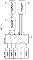
- FIG. 3 is a conceptual block diagram for explaining a first conversion mode in which MIDI-to-icon conversion is performed selectively on a part of tune data by using a channel filtering function in the performance data editing system of the present embodiment.
- the tune data include MIDI data of plural channels (or plural parts) 1 to n. That is, a channel selector SL1 is controlled by the operation device 13 which is operated by a user to designate a specific MIDI channel, so that a part Dc1 of the tune data is being selected.
- the MIDI-to-icon conversion block IC performs MIDI-to-icon conversion selectively on the part Dc1 of the tune data being selected by the channel selector SL1, thus producing converted data Dc1', which is supplied to the execution-related sound source AS.
- a remaining part Dc2 of the tune data which is not selected by the channel selector SL1 is supplied to a normal sound source NS as non-conversion data Dc2.
- the converted data Dc1' and non-conversion data Dc2 are temporarily recorded on the sequencer, then, they are reproduced and supplied to the sound sources AS, NS respectively.
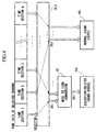
- FIG. 4 is a conceptual block diagram for explaining a second conversion mode in which MIDI-to-icon conversion is performed selectively on a part of tune data by using a time section designation function in the performance data editing system of the present embodiment.
- tune data of plural channels 1 to n among which tune data of a certain channel is selected.
- the tune data of the selected channel is divided into plural time sections 1 to m with respect to time.
- MIDI data which is subjected to conversion are displayed on the screen of the display 14, then, the user operates the operation device 13 such as the mouse to designate a desired time section. This activates a time section selector SL2 to select data Dt1 corresponding to a certain time section being selected from among plural time sections 1 to m, for example.
- the MIDI-to-icon conversion block IC performs MIDI-to-icon conversion on the data Dt1 of the selected time section, thus producing converted data Dt1', which is supplied to the execution-related sound source AS.
- Data Dt2 of remaining time sections which are not selected by the time section selector SL2 are supplied to the normal sound source NS as non-conversion data Dt2.
- the sequencer as shown in FIG. 2. That is, the converted data Dt1' and non-conversion data Dt2 are temporarily recorded on the sequencer, then, they are reproduced and supplied to the sound sources AS, NS respectively.
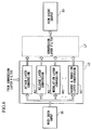
- FIGS. 5 and 6 are conceptual block diagrams for explaining third and fourth conversion modes in which MIDI-to-icon conversion is performed selectively on a part of specific types of data by using a layer filtering function in the performance data editing system of the present embodiment.
- MIDI data input by the MIDI data input block DI are classified into specific types of data respectively corresponding to multiple execution icon layers with respect to musical parameters such as attack, release, modulation, accent & duration, etc.
- the execution icon layers correspond to groups of execution icons which are obtained through the MIDI-to-icon conversion.
- one of the specific types of data is selected and is selectively subjected to MIDI-to-icon conversion via an icon layer conversion block LC.
- the icon layer conversion block is configured by an attack layer conversion block AC, a release layer conversion block RC, a modulation layer conversion block MC, an accent & duration layer conversion block SC, etc.
- Each of the layer conversion blocks AC, RC, MC, SC, etc. is connected with a conversion layer filter LF (see FIG. 5) or a conversion layer filter LF' (see FIG. 6).
- a MIDI-to-execution-icon conversion set SS is provided to enable the MIDI-to-icon conversion being selectively performed on a part of the specific types of data.
- the MIDI-to-execution-icon conversion set SS defines relationships by which different types of data within the MIDI data are respectively related to different types of execution icons, so that each type of data is being converted to its corresponding type of the execution icon.
- the MIDI-to-execution-icon conversion set SS corresponds to multiple sets 1, 2, ... and a user set US, which are stored in a prescribed storage area of the external storage device 9. FIG.
- FIG. 5 shows an example of content of the set 1 consisting of plural columns, each of which defines its own execution icons in an upper section and subject data for conversion in a lower section.
- a first column defines that pitch bend data of MIDI data is converted to an icon of "bend-up/down”.
- "none" is described as the subject data, so that no conversion is made with respect to an icon of "grace-up/down”.
- a set selector SL3 is activated to select any one of the aforementioned sets in the MIDI-to-execution-icon conversion set SS, so that the selected set is temporarily stored in a buffer BF.
- the conversion layer filter LF is activated to select a desired execution icon layer. That is, the conversion layer filter LF has a function of selecting from among the plural execution icon layers (e.g., attack icon layer, release icon layer, etc.) a desired execution icon layer on which MIDI-to-icon conversion is to be performed.
- the MIDI-to-icon conversion defines types of execution icons being converted with respect to each execution icon layer.
- the attack icon layer is related to execution icons of bend-up/down and grace-up/down. If the user selects the set 1 while the attack icon layer allows MIDI-to-icon conversion, the conversion layer filter LF activates the attack layer conversion block AC (see FIG. 6) so that on the basis of the content of the selected set 1, pitch bend data of MIDI data is selected as a subject to the MIDI-to-icon conversion. Thus, the pitch bend data is converted to an execution icon of bend-up/down, which is supplied to an icon event output block IO as execution icon data.
- the conversion layer filter LF is provided as an activator for activating the layer conversion blocks AC, RC, MC, SC respectively.
- the conversion layer filter LF' (encompassed by a dotted line) is provided as an output controller for controlling outputs of the layer conversion blocks AC, RC, MC, SC respectively.
- each layer conversion block (e.g., AC, SC) performs MIDI-to-icon conversion in response to the content of the conversion set temporarily stored in the buffer BF.
- MIDI data regarding the layer conversion block(s) which is not activated are directly transmitted by the conversion layer filter LF' without conversion.
- the present embodiment provides an edit block ED (see FIG. 5) by which it is possible to correct the content of the conversion set temporarily stored in the buffer BF.
- the corrected content of the conversion set can be stored as the user set US.
- the user set US it is possible to propose the user set US as a desired conversion set being selected from the MIDI-to-execution-icon conversion set SS, wherein the user set US is read and temporarily stored in the buffer BF by way of the set selector SL3.
- it is possible to re-design the MIDI-to-execution-icon conversion set SS such as to store plural user sets US.
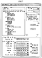
- FIG. 7 shows an example of the conversion dialogue window for a specific musical instrument of a saxophone. Details of procedures in operations of the MIDI-to-icon conversion will be described below with reference to FIG. 7.
- a mode selection area (“Converter Filter”) SA describes three modes, i.e., a non-conversion mode ("Note Only”), a collective conversion mode ("Note, All of Articulation Icon Layer”) and a successive conversion mode (“Note, Articulation Icon Layer as follow”), each of which is preceded by a mode selection box " ⁇ ".
- the successive conversion mode is designated, so that the display 14 displays on the screen its selectable execution icon layers (e.g., Attack, Release, ..., Accent & Duration), each of which is preceded by execution icon layer selection box " ⁇ ".
- each of the execution icon layers is related to plural execution icons (e.g., BendUp/Down, GraceUp/Down), each of which is preceded by an output icon selection box " ⁇ ".
- the user operates the operation device 13 such as the mouse to check a mode selection box " ⁇ " to designate a desired conversion mode, then, the user clicks a conversion button ("Convert") CB with the mouse so that MIDI-to-icon conversion is carried out in response to the designated mode.
- the user checks the execution icon layer selection box to select a desired execution icon layer for conversion and also checks the output icon selection box to set a desired execution icon.
- the present embodiment provides a number of selectable execution icon layers, examples of which are described together with their execution icons (followed by arrows " ⁇ "), as follows:
- the MIDI-to-icon conversion produces execution-related event information, which is configured by note events, execution icon events and time data.
- the note events are configured by note data, velocity data and gate time data.
- the execution icon events are configured by execution icon IDs and execution icon parameters.
- the aforementioned execution icons which are followed by arrows in the aforementioned paragraphs (1) to (7) regarding the execution icon layers, are output in response to execution icon ID data.
- the execution icon parameters represent icon parameter values of the execution icons on which corresponding events occur. There are provided a variety of execution icon parameters with regard to execution time data representing execution occurrence times and execution end times, execution lengths, break-point times and depths.
- time data representing occurrence times of events respectively
- event interval times or delta times
- each of which represents a time interval between a present event and a previous event corresponding to a note event, an execution icon event or else.
- the time data are described based on a SMF format.
- the execution-related events may include other original data such as pitch bends and modulations, which are not selected as subjects to the MIDI-to-icon conversion.
- FIG. 7 shows that the user presently checks two layer selection boxes regarding the attack execution icon layer and release execution icon layer and also checks their output icon selection boxes regarding the execution icons of bend-up/down.
- the conversion button CB the MIDI-to-icon conversion is adequately performed in accordance with the aforementioned setting. Thus, it produces note events together with corresponding execution icon events.
- an output destination of the execution icons which are produced by the MIDI-to-icon conversion, by using an output setting area ("OutPut") OA, which shows columns for a track number and a part name. That is, the user is capable of inputting a track number into an upper column to designate a track on which the execution icon events are being output. In addition, the user is capable of inputting a part name into a lower column to designate a part which corresponds to an output destination.
- OutPut output setting area
- the conversion dialogue window also shows a monitor audition area ("Monitor”) MA, by which the user is capable of listening to sounds of MIDI data before conversion as well as sounds of execution-related data after conversion by audition.
- the monitor audition area MA indicates two check boxes with respect to the MIDI data before conversion (“Input track”) and the execution-related data after conversion (“Output track”), one of which is being checked and designated by the user. That is, when the user operates a listen button (“Listen”) LB provided in the monitor audition area MA, the aforementioned musical tone output section (7, 8, 15) of the system produces musical tones based on the MIDI data before conversion or execution-related data after conversion in accordance with designation of "Input track” or "Output track”.
- the MIDI-to-execution-icon conversion set SS defines input/output relationships between the MIDI data being subjected to conversion and the execution icons being produced by the conversion.
- a prescribed storage area of the ROM 2 or external storage device 9 stores in advance plural MIDI-to-execution-icon conversion sets, which are set in response to musical instruments being designated.
- the user performs a set selection operation on the operation device 13 so that a desired MIDI-to-execution-icon conversion set corresponding to a specific musical instrument is selectively read out on the conversion dialogue window displayed on the screen of the display 14.
- the conversion dialogue window of FIG. 7 provides an input/output selection area ("From MIDI to AI") EA, which contains a conversion set name column CS for the MIDI-to-execution-icon conversion set and plural data name columns CM for MIDI data of tune data.
- EA input/output selection area
- the MIDI-to-execution-icon conversion set SS corresponding to the designated musical instrument can be selected by using the conversion set name column CS.
- contents of the input/output relationships defined by the selected MIDI-to-execution-icon conversion set are reflected on the data name columns CM, by which the user is capable of visually recognizing the concrete content of the selected MIDI-to-execution-icon conversion set.
- the prescribed storage area of the ROM 2 or external storage area 9 stores in advance three types of MIDI-to-execution-icon conversion sets (1) to (3).
- FIG. 7 shows that the input/output selection area EA indicates contents of "MIDI-to-execution-icon conversion set 1 (saxophone)", as follows:
- the present embodiment allows the user to perform a variety of editing operations, such as save and delete in addition to correction of input/output relationships, with respect to the MIDI-to-execution-icon conversion set SS being selectively read out on the input/output selection area EA of the conversion dialogue window displayed on the screen of the display 14.
- the user is capable of correcting a name of the MIDI-to-execution-icon conversion set shown in the conversion set name column CS as well as names (or types) of parameters of tune data shown in the data name column CM.
- Each of musical instruments is related to a different type of "convertible" MIDI data which can be converted to execution icons.
- the convertible MIDI data can be selected from among a prescribed range of MIDI data which are set for the execution icons being designated in advance. That is, a composer (i.e., user) is capable of performing the conversion with preferable variations within a prescribed range of executions.
- certain "selectable" MIDI data being selected in the data name columns CM of tune data are predetermined in connection with the execution icons which are produced by the conversion. Examples are listed below.
- the user operates a save button ("Save") SB so that the MIDI-to-execution-icon conversion set SS, which is selected and edited on the screen, is updated and saved under a present name.
- the user operates a save as button ("Save As") AB so that the MIDI-to-execution-icon conversion set SS, which is selected and edited on the screen, can be additionally saved under a new name as a user set US.
- the system provides prescribed procedures for "save as" as follows:
- the user operates the save as button AB, so that a file dialogue (not shown) is open to allow entry of a file name. So, the user inputs a new file name and operates a save button (not shown) provided within the file dialogue.
- the edited MIDI-to-execution-icon conversion set is saved under a new conversion set name corresponding to the new file name.
- the saved MIDI-to-execution-icon conversion set is proposed as a new selectable conversion set for a new set selection operation of the user, so that it can be read out in the input/output selection area EA according to needs.
- Delete a delete button
- the user operates a delete button ("Delete") DB, so that all data of the MIDI-to-execution-icon conversion set presently selected are deleted from the storage area. Thereafter, the deleted conversion set will not be read out in the input/output selection area EA even when the user performs a new set selection operation.
- the present embodiment is designed to store plural MIDI-to-execution-icon conversion sets (SS) in advance.
- SS MIDI-to-execution-icon conversion sets
- the MIDI-to-execution-icon conversion sets can be arbitrarily selected and edited, hence, edit results can be saved as the user set US.
- the composer i.e., user
- the composer is capable of arbitrarily selecting necessary types of MIDI data, which are needed for conversion to execution icons.
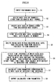
- FIG. 8 is a flowchart showing an example of a process of MIDI-to-icon conversion in accordance with the embodiment of the invention. This flowchart (or flow) is directed to the MIDI-to-icon conversion wherein a specific type of MIDI data corresponds to a modulation event which is being converted to a vibrato icon event in the performance data editing system of the present embodiment.
- input modulation events are described by occurrence times and data values thereof, while vibrato icon events which are produced by the conversion are described by vibrato icon occurrence times and vibrato icon parameters.
- vibrato icon parameters there are provided lengths, start times, start depths, first break-point times, first break-point depths, second break-point times, second break-point depths, ..., n-th break-point times, n-th break-point depths and end depths.
- a sound effect of vibrato is imparted to musical tones.
- the sound source circuit 7 converts the modulation events to prescribed parameters such as vibrato depths (i.e., depths in pitch variations) and vibrato speeds (i.e., speeds in pitch variations).
- vibrato depths i.e., depths in pitch variations
- vibrato speeds i.e., speeds in pitch variations.
- the vibrato is imparted to the musical tones based on the aforementioned parameters.
- parameters such as vibrato depths and vibrato speeds are produced as vibrato icon parameters based on modulation events.
- the aforementioned parameters are not necessarily produced based on the modulation events, in other words, some parts of the parameters can be fixed at prescribed values or constant values which can be set again.
- the following description is made under a precondition that the vibrato speeds are fixedly set in advance while the vibrato depths are newly produced based on the modulation events.
- the present embodiment defines in advance certain characteristics in production of the vibrato depths being produced based on the modulation events. For example, the present embodiment defines in advance a value of the vibrato depth which is produced based on the modulation event having a maximal value of "127".
- step S1 allows the user to input performance data.
- SMF data hereinafter, referred to as "MIDI data”
- MIDI data SMF data
- step S2 the system uses a MIDI channel filter to delete MIDI data of unwanted channels (other than a designated MIDI channel) from the input MIDI data.
- step S3 the system uses a MIDI message filter to further delete MIDI data of unwanted MIDI events (other than designated MIDI events) from the input MIDI data.
- MIDI data of only the designated MIDI events it is possible to select MIDI data of only the designated MIDI events.
- step S3 at least modulation events within MIDI messages are being selected or filtered.
- modulation occurrence times, data values and data attributes (data/noise) it is possible to obtain modulation occurrence times, data values and data attributes (data/noise) with respect to all modulation data which are read into the system.
- step S4 the selected MIDI data (e.g., modulation occurrence times, data values) which are selected from among the input MIDI data by the steps S2, S3 are stored in a prescribed memory area of the RAM 3.
- step S5 the system deletes noise data (or data which are regarded as noise) from the selected MIDI data, so that the noise data are excluded from subjects for MIDI-to-icon conversion.
- step S6 the system detects time sections in which high data values which are higher than a prescribed data value in the MIDI data continuously emerge for a prescribed time or more. So, the system extracts start times, end times and peak values with respect to the detected time sections respectively.
- step S7 the system produces by calculations icon parameters (e.g., vibrato depths) which correspond to the MIDI data belonging to the detected time sections respectively.
- step S8 the system outputs the calculated icon parameters.
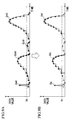
- FIG. 9A shows modulation data which correspond to a data string containing data elements each indicated by a hatching-square symbol (i.e., a square symbol " ⁇ " with hatching).
- FIG. 9A shows that the modulation data contain four data blocks Dao, Dbo, Dco and Ddo, each of which is drawn as a specific waveform having a peak.
- a data threshold Vt corresponding to a prescribed data value is set for a level judgement process being performed on the modulation data of FIG. 9A. So, parts of the modulation data which are under the data threshold Vt are regarded as noise components, which are deleted and are excluded from conversion subjects to the MIDI-to-icon conversion. Herein, the data block Dco is entirely deleted. Due to the level judgement process, modulation data strings Da, Db and Dd (see FIG. 9B) containing data elements whose values are above the data threshold Vt are extracted from the modulation data. That is, as shown in FIG.
- the system discriminates from the modulation data the modulation data strings having data elements whose values are above the data threshold Vt and each of which is indicated by the hatching-square symbol, while the system excludes other data elements whose values are under the data threshold Vt and each of which is indicated by a blank-square symbol (i.e., " ⁇ ").
- ⁇ blank-square symbol
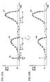
- a time threshold Tt corresponding to a prescribed time length is set for a time judgement process being performed on the modulation data strings including the data elements whose values exceed the data threshold Vt.
- the modulation data string(s) which is not continuously sustained for the time threshold Tt or more are regarded as noise components, which are excluded from the conversion subjects of the MIDI-to-icon conversion.
- the time judgement process is performed on the modulation data strings Da, Db and Dd containing the data elements whose values consecutively exceed the data threshold Vt and which have sustaining times Ta, Tb and Td respectively.
- the system extracts all the modulation data strings from which the noise components are eliminated and each of which is formed by the consecutive data elements having finite values with respect to time.
- the extracted modulation data strings are temporarily stored in a prescribed memory area. Namely, as shown in FIG. 11, the modulation data strings Db and Dd are respectively stored as modulation storage blocks Bn and Bn+1.
- a characteristic extraction process of step S6 for extracting characteristics such as a start time and an end time from each time section containing data elements whose values are equal to or above the prescribed data value and which are consecutively sustained for a prescribed time or more.
- the characteristic extraction process deals with the modulation data blocks (e.g., Bn) containing "noise-eliminated" modulation data strings (each designated by a symbol "D") which are stored in the foregoing step S5.
- the characteristic extraction process extracts characteristics of the modulation data strings, which are stored again to update data.
- FIG. 12A shows an example of the modulation data string D containing data elements which are indicated by hatching-square symbols and which are defined between start-point data Pa and end-point data Pb.
- extrapolation is effected to determine two points of intersection at which extensions from Pa and Pb intersect with a zero level of an axis of "data value V". Those points of intersection are regarded as a modulation start time ts and a modulation end time te respectively.
- a terminal-added modulation data string De (see FIG. 13) which incorporates terminal data (designated by blank-square symbols) corresponding to the aforementioned times ts and te in addition to the data elements (designated by hatching-square symbols) of the modulation data string D.
- content of the modulation storage block e.g., Bn
- FIG. 12A shows a simple example of calculations for extrapolation. That is, extrapolation regarding the modulation start time ts is simply effected in response to a variation between the start-point data Pa and its adjacent point data Pa+1 in the modulation data string D, so that the system simply calculates the modulation start time ts. Similarly, extrapolation regarding the modulation end time te is simply effected in response to a variation between the end-point data Pb and its adjacent point data Pb-1 in the modulation data string D, so that the system simply calculates the modulation end time te.
- FIG. 12B shows another example of calculations for extrapolation, wherein a modulation data string D contains data elements which are defined between start-point data Pa having a data value Vs and end-point data Pb having a data value Ve.
- the system creates a dummy point Pds, which has a double data value 2Vs and which is located on a waveform of the modulation data string D in proximity to the start point Pa.
- the system calculates a time interval Tds between the start point Pa and the dummy point Pds, so that a start time ts is set at a time point which precedes from a time ta of the start point Pa by the time interval Tds.
- the system creats a dummy point Pde, which has a double data value 2Ve and which is located on the waveform of the modulation data string D in proximity to the end point Pb. Then, the system calculates a time interval Tde between the dummy point Pde and the end point Pb, so that an end time te is set at a time point which delays from a time tb of the end point Pb by the time interval Tde.
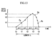
- FIG. 13 shows an example of the terminal-added modulation data string De which is produced by the characteristic extraction process of step S6 and which incorporates the start-point data Pa and end-point data Pb in addition to the data elements (indicated by hatching-square symbols).
- a time interval L between the modulation start time ts and modulation end time te is regarded as a length of an icon parameter.
- An overall waveform of the terminal-added modulation data string De defined between the start time ts and end time te is equally divided into "n" (where "n” is an integer arbitrarily selected) time sections, split time points of which are called break-point times.
- Data values of the terminal-added modulation data string De at the break-point times t1, t2 and t3 are calculated by effecting linear interpolation on the MIDI data.
- first, second and third break-point data values V1, V2, V3 are respectively calculated using the linear interpolation being effected on the terminal-added modulation data string De with respect to the first, second and third break-point times t1, t2, t3.
- the system calculates break-point depths from the break-point data values V1, V2, V3 as icon parameters.
- This invention is not necessarily limited to the present embodiment which is described heretofore to provide a specific conversion algorithm for converting the tune data to the execution-related data and a specific format of the execution-related data, which are merely examples.
- automatic performance data of plural channels can be stored in a channel-mixture manner that data of the plural channels are mixed without sorting or alignment in storage or in a channel-independence manner that data of each channel is stored on its corresponding track in storage.
- memory management is made such that time-series performance data are stored in consecutive areas, or multiple data stored in different areas which are arranged at intervals are collectively managed as consecutive data.
- the present embodiment requires that performance data can be managed as time-series consecutive data on the memory. So, the present embodiment does not put a question as to whether the performance data are stored in the memory consecutively or not.
Landscapes
- Engineering & Computer Science (AREA)
- Physics & Mathematics (AREA)
- Acoustics & Sound (AREA)
- Multimedia (AREA)
- General Engineering & Computer Science (AREA)
- Electrophonic Musical Instruments (AREA)
Applications Claiming Priority (2)
| Application Number | Priority Date | Filing Date | Title |
|---|---|---|---|
| JP26776799 | 1999-09-21 | ||
| JP26776799A JP3674407B2 (ja) | 1999-09-21 | 1999-09-21 | 演奏データ編集装置、方法及び記録媒体 |
Publications (1)
| Publication Number | Publication Date |
|---|---|
| EP1087367A1 true EP1087367A1 (fr) | 2001-03-28 |
Family
ID=17449313
Family Applications (1)
| Application Number | Title | Priority Date | Filing Date |
|---|---|---|---|
| EP00120484A Withdrawn EP1087367A1 (fr) | 1999-09-21 | 2000-09-19 | Méthode et dispositif pour le traitement de données d'exécution au moyen d'icônes représentant des symboles musicaux |
Country Status (3)
| Country | Link |
|---|---|
| US (1) | US6570081B1 (fr) |
| EP (1) | EP1087367A1 (fr) |
| JP (1) | JP3674407B2 (fr) |
Cited By (2)
| Publication number | Priority date | Publication date | Assignee | Title |
|---|---|---|---|---|
| CN1851802B (zh) * | 2006-05-29 | 2010-10-13 | 安凯(广州)微电子技术有限公司 | 一种基于midi的提高有效和弦的方法 |
| WO2017136854A1 (fr) * | 2016-02-05 | 2017-08-10 | New Resonance, Llc | Mappage de caractéristiques de musique en affichage visuel |
Families Citing this family (12)
| Publication number | Priority date | Publication date | Assignee | Title |
|---|---|---|---|---|
| JP3758450B2 (ja) * | 2000-01-10 | 2006-03-22 | ヤマハ株式会社 | 曲データ作成のためのサーバ装置、クライアント装置及び記録媒体 |
| US20010055037A1 (en) * | 2000-06-16 | 2001-12-27 | Pallett Michael J. | Communications system, article of manufacture and method related to modifying operation of a communications system |
| JP4586268B2 (ja) * | 2000-12-25 | 2010-11-24 | ヤマハ株式会社 | ネットワークにおけるデータ送受信管理方法及び同データ送受信管理装置 |
| JP2003330464A (ja) * | 2002-05-14 | 2003-11-19 | Casio Comput Co Ltd | 自動演奏装置および自動演奏方法 |
| JP4614307B2 (ja) | 2003-09-24 | 2011-01-19 | ヤマハ株式会社 | 演奏データ処理装置及びプログラム |
| US7424333B2 (en) * | 2004-12-22 | 2008-09-09 | Musicgiants, Inc. | Audio fidelity meter |
| US7462772B2 (en) * | 2006-01-13 | 2008-12-09 | Salter Hal C | Music composition system and method |
| US7663046B2 (en) * | 2007-03-22 | 2010-02-16 | Qualcomm Incorporated | Pipeline techniques for processing musical instrument digital interface (MIDI) files |
| JP4623060B2 (ja) * | 2007-07-18 | 2011-02-02 | ヤマハ株式会社 | 波形生成装置、音響効果付与装置、および楽音発生装置 |
| JP5461846B2 (ja) * | 2009-02-12 | 2014-04-02 | 株式会社河合楽器製作所 | スケール変換装置、方法及びプログラム |
| JP5215899B2 (ja) * | 2009-02-12 | 2013-06-19 | 株式会社河合楽器製作所 | 音価変更装置、方法及びプログラム |
| DE102009014655A1 (de) * | 2009-03-25 | 2010-10-07 | Schippmann, Carsten, Dipl.-Ing. | Verfahren zur Interpolation von MIDI Daten |
Citations (3)
| Publication number | Priority date | Publication date | Assignee | Title |
|---|---|---|---|---|
| EP0484046A2 (fr) * | 1990-11-01 | 1992-05-06 | International Business Machines Corporation | Méthode et dispositif pour la préparation de fichiers MIDI |
| US5684259A (en) * | 1994-06-17 | 1997-11-04 | Hitachi, Ltd. | Method of computer melody synthesis responsive to motion of displayed figures |
| US5852251A (en) * | 1997-06-25 | 1998-12-22 | Industrial Technology Research Institute | Method and apparatus for real-time dynamic midi control |
Family Cites Families (7)
| Publication number | Priority date | Publication date | Assignee | Title |
|---|---|---|---|---|
| US4496569A (en) | 1983-03-25 | 1985-01-29 | The Dow Chemical Company | Antiallergic (1H-tetrazol-5-yl)tetrazolo[1,5-a]quinolines and derivatives thereof |
| JPH05127673A (ja) | 1991-10-30 | 1993-05-25 | Roland Corp | 楽譜パラメータ入力装置 |
| JP3622275B2 (ja) | 1995-06-22 | 2005-02-23 | ヤマハ株式会社 | 自動演奏の制御データ入力方法および自動演奏装置 |
| JP3407610B2 (ja) | 1996-11-27 | 2003-05-19 | ヤマハ株式会社 | 楽音生成方法および記憶媒体 |
| EP1094442B1 (fr) | 1996-11-27 | 2005-01-19 | Yamaha Corporation | Méthode de génération de sons musicaux |
| US5913258A (en) * | 1997-03-11 | 1999-06-15 | Yamaha Corporation | Music tone generating method by waveform synthesis with advance parameter computation |
| DE69836393T2 (de) * | 1997-09-30 | 2007-09-06 | Yamaha Corp., Hamamatsu | Verfahren, Vorrichtung und maschineslesbares Speichermedium zur Klangsynthesierung |
-
1999
- 1999-09-21 JP JP26776799A patent/JP3674407B2/ja not_active Expired - Fee Related
-
2000
- 2000-09-15 US US09/663,318 patent/US6570081B1/en not_active Expired - Fee Related
- 2000-09-19 EP EP00120484A patent/EP1087367A1/fr not_active Withdrawn
Patent Citations (3)
| Publication number | Priority date | Publication date | Assignee | Title |
|---|---|---|---|---|
| EP0484046A2 (fr) * | 1990-11-01 | 1992-05-06 | International Business Machines Corporation | Méthode et dispositif pour la préparation de fichiers MIDI |
| US5684259A (en) * | 1994-06-17 | 1997-11-04 | Hitachi, Ltd. | Method of computer melody synthesis responsive to motion of displayed figures |
| US5852251A (en) * | 1997-06-25 | 1998-12-22 | Industrial Technology Research Institute | Method and apparatus for real-time dynamic midi control |
Non-Patent Citations (1)
| Title |
|---|
| RIDEOUT E: "CAKEWALK METRO 4.5", KEYBOARD,US,MILLER FREEMAN PUBLICATIONS, SAN FRANCISCO, vol. 25, no. 1, January 1999 (1999-01-01), pages 84,86,88 - 90, XP000790387, ISSN: 0730-0158 * |
Cited By (4)
| Publication number | Priority date | Publication date | Assignee | Title |
|---|---|---|---|---|
| CN1851802B (zh) * | 2006-05-29 | 2010-10-13 | 安凯(广州)微电子技术有限公司 | 一种基于midi的提高有效和弦的方法 |
| WO2017136854A1 (fr) * | 2016-02-05 | 2017-08-10 | New Resonance, Llc | Mappage de caractéristiques de musique en affichage visuel |
| US10978033B2 (en) | 2016-02-05 | 2021-04-13 | New Resonance, Llc | Mapping characteristics of music into a visual display |
| US12230239B2 (en) | 2016-02-05 | 2025-02-18 | New Resonance, Llc | Mapping characteristics of music into a visual display |
Also Published As
| Publication number | Publication date |
|---|---|
| JP2001092451A (ja) | 2001-04-06 |
| US6570081B1 (en) | 2003-05-27 |
| JP3674407B2 (ja) | 2005-07-20 |
Similar Documents
| Publication | Publication Date | Title |
|---|---|---|
| US5939654A (en) | Harmony generating apparatus and method of use for karaoke | |
| US6570081B1 (en) | Method and apparatus for editing performance data using icons of musical symbols | |
| CN1173008A (zh) | 分析相对于旋律数据的演唱声的卡拉ok评分装置 | |
| JP3829549B2 (ja) | 楽音生成装置及びテンプレート編集装置 | |
| JP2000231381A (ja) | メロディ生成装置及びリズム生成装置と記録媒体 | |
| JP2002023747A (ja) | 自動作曲方法と装置及び記録媒体 | |
| JP3266149B2 (ja) | 演奏ガイド装置 | |
| JP5887293B2 (ja) | カラオケ装置及びプログラム | |
| JP3489503B2 (ja) | 音信号分析装置、音信号分析方法及び記憶媒体 | |
| US7200813B2 (en) | Performance information edit and playback apparatus | |
| EP1391873A1 (fr) | Dispositif et méthode pour déterminer le style d'interprétation | |
| JP3709821B2 (ja) | 楽曲情報編集装置及び楽曲情報編集プログラム | |
| US6476305B2 (en) | Method and apparatus for modifying musical performance data | |
| JP3587133B2 (ja) | 発音長決定方法と装置及び記録媒体 | |
| JP2002304175A (ja) | 波形生成方法、演奏データ処理方法および波形選択装置 | |
| JP3329242B2 (ja) | 演奏データ分析装置および演奏データ分析プログラムを記録した媒体 | |
| JP3371774B2 (ja) | 演奏データから和音を検出する和音検出方法および和音検出装置、ならびに、和音検出用プログラムを記録した記録媒体 | |
| JP3669335B2 (ja) | 自動演奏装置 | |
| JPH11184465A (ja) | 演奏装置 | |
| JP4178661B2 (ja) | 教示データ生成装置、及び記録媒体 | |
| JP4186802B2 (ja) | 自動伴奏生成装置及びプログラム | |
| JP3709820B2 (ja) | 楽曲情報編集装置及び楽曲情報編集プログラム | |
| JP3797180B2 (ja) | 楽譜表示装置及び楽譜表示プログラム | |
| JP2003099039A (ja) | 楽曲データ編集装置及びプログラム | |
| JP4154600B2 (ja) | 自動伴奏生成プログラム及び自動伴奏生成装置 |
Legal Events
| Date | Code | Title | Description |
|---|---|---|---|
| PUAI | Public reference made under article 153(3) epc to a published international application that has entered the european phase |
Free format text: ORIGINAL CODE: 0009012 |
|
| 17P | Request for examination filed |
Effective date: 20000919 |
|
| AK | Designated contracting states |
Kind code of ref document: A1 Designated state(s): DE GB IT |
|
| AX | Request for extension of the european patent |
Free format text: AL;LT;LV;MK;RO;SI |
|
| AKX | Designation fees paid |
Free format text: DE GB IT |
|
| RAP1 | Party data changed (applicant data changed or rights of an application transferred) |
Owner name: YAMAHA CORPORATION |
|
| GRAP | Despatch of communication of intention to grant a patent |
Free format text: ORIGINAL CODE: EPIDOSNIGR1 |
|
| RIC1 | Information provided on ipc code assigned before grant |
Ipc: G10H 7/00 20060101ALI20140905BHEP Ipc: G10H 1/02 20060101ALI20140905BHEP Ipc: G10H 1/00 20060101AFI20140905BHEP |
|
| INTG | Intention to grant announced |
Effective date: 20141015 |
|
| STAA | Information on the status of an ep patent application or granted ep patent |
Free format text: STATUS: THE APPLICATION IS DEEMED TO BE WITHDRAWN |
|
| 18D | Application deemed to be withdrawn |
Effective date: 20150226 |