EP1087414B1 - Schalteinrichtungen - Google Patents
Schalteinrichtungen Download PDFInfo
- Publication number
- EP1087414B1 EP1087414B1 EP00308278A EP00308278A EP1087414B1 EP 1087414 B1 EP1087414 B1 EP 1087414B1 EP 00308278 A EP00308278 A EP 00308278A EP 00308278 A EP00308278 A EP 00308278A EP 1087414 B1 EP1087414 B1 EP 1087414B1
- Authority
- EP
- European Patent Office
- Prior art keywords
- body part
- assembly according
- base structure
- projection
- push button
- Prior art date
- Legal status (The legal status is an assumption and is not a legal conclusion. Google has not performed a legal analysis and makes no representation as to the accuracy of the status listed.)
- Expired - Lifetime
Links
Images

Classifications
-
- H—ELECTRICITY
- H01—ELECTRIC ELEMENTS
- H01H—ELECTRIC SWITCHES; RELAYS; SELECTORS; EMERGENCY PROTECTIVE DEVICES
- H01H13/00—Switches having rectilinearly-movable operating part or parts adapted for pushing or pulling in one direction only, e.g. push-button switch
- H01H13/02—Details
- H01H13/023—Light-emitting indicators
-
- H—ELECTRICITY
- H01—ELECTRIC ELEMENTS
- H01H—ELECTRIC SWITCHES; RELAYS; SELECTORS; EMERGENCY PROTECTIVE DEVICES
- H01H2229/00—Manufacturing
- H01H2229/042—Snap coupling; Snap mounting
Definitions
- a known illuminated push button electrical switch assembly as commonly used in amusement and gaming machines, has a base structure with a microswitch and a lamp holder, and a tubular body part which fits around the lamp holder at one end and has a push button at the opposite end. Within the body part there is a slider element which is moved by the push button to operate the microswitch.
- the slider element is a tubular structure with a pair of diametrically opposed feet for engagement with an operating member of the microswitch.
- the body part and the base structure are detachably interconnected by bayonet fittings i.e. by diametrically opposed radially outwardly extending pins on the base structure which engage diametrically opposed L-shaped slots in the adjacent peripheral region of the body part.
- the base structure is united with the body part with- a push and twist movement which is intended to retain the base structure in the correct position relative to the body part so that one of the feet is aligned with the operating member of the microswitch.
- An object of the present invention is to provide an alternative means of detachable interengagement between the base structure and the body part which is of a simple and convenient nature yet which can give reliable relative positioning of the base structure and body part.
- Assembly and disassembly can therefore be effected in a particularly simple and convenient manner, and, in the assembled condition the base structure can be reliably retained in a desired circumferential position relative to the body part having regard to the close circumferential fit between the projection and the aperture.
- the projection is provided on the base structure and the aperture is provided on the body part.
- the projection is transversely resiliently deflectable and this may be achieved by providing the projection on a deflectable arm.
- the aperture may comprise a recess or a through hole. The resilience is preferably such as to give a snap fit.
- the interfitting elements may comprise two projections, with respective apertures, as aforesaid, and these may be arranged at diametrically opposed locations so that the body part and the base structure can be selectively assembled in either or two different positions rotated through 180°.
- a guide arrangement may be provided to direct axial movement of the base structure relative to the body part to bring the (or each) projection into engagement with the (or each) aperture.
- This may comprise a respective track (or channel) for the (or each) aperture which may be defined in any suitable manner, e.g. by raised ridges or a recessed portion or the like.
- the body part may comprise a cylindrical structure which is threaded on its outer surface to receive a correspondingly internally threaded annular member, and which has an enlarged head at the outer end to receive and locate the push button, whereby the body part can be fixed in a mounting hole in a panel by clamping the panel between the head and the internally threaded annular member.
- the head part, and correspondingly the push button may be square or rectangular, or circular or of any other suitable shape.
- the body part may be elongate with a relatively axially short head.
- the body part may be short and the head may be of similar or even greater axial length.
- the push button and/or the head of the body part may be transparent or translucent to permit transmission of illumination from a lamp in the lamp holder.
- the internal slider element may take any suitable form.
- the slider element may have different parts for operative engagement with the microswitch respectively in the different positions. These different parts may comprise diametrically opposed axially projecting feet.
- the slider element may comprise a tubular element coaxially within the tubular body part.
- a spring device may be provided between the body part and the slider element to resist pushing of the push button.
- This may comprise a helical coil spring which may fit between an internal projection at the inner end of the body part and a projection on the slider element at the outer end of the body part. Travel of the slider element under the action of the spring device may be limited by interengagement of the slider element and the inner end region of the body part. Conveniently the aforesaid feet may have outwardly turned ends for such limiting interengagement with the body part.
- the lamp holder and microswitch may comprise attached separately encased components. Alternatively, they may be provided as printed circuit board components in a common housing.
- the switch assembly of the invention is particularly suited for use in an amusement or gaming machine but may be used in any other suitable context.
- the switch assembly shown in the drawings is for use for player operation in an amusement or gaming machine, such as a fruit machine, or poker machine, or other slot machine.
- the switch assembly is mounted in a mounting hole of a panel 1 of the machine as indicated in Figure 1.
- the assembly has a body part 2 and a base structure 3.
- the body part 2 comprises a one-piece plastics moulding which has a cylindrical section 4 with an external thread along its entire length and an integral radially outwardly extending flat circular rim 5 at the outer end of the body part.
- a circular collar 6 is attached around this rim and a transparent or translucent push button 7 of hollow disc-shaped form fits slidably within the head defined by the rim 5 and the collar 6.
- the push button 7 is provided with decoration and/or information visible at its outer surface.
- the push button 7 is formed integrally with the outer end of a slider element 8 within the cylindrical section 4.
- This slider element 8 comprises a moulded plastics cylindrical tube 9 with two axially projecting narrow strip-shaped feet 10 at diametrically opposed positions at its inner end.
- the feet 10 have radially outwardly turned ends 11.
- This tube 9 is located coaxially within the cylindrical section 4 of the body part 2 and is of smaller diameter so that it can slide freely along the cylindrical section 4.
- the outwardly turned ends 11 of the feet 10 project beyond the cylindrical section 4.
- the feet 10 can be resiliently squeezed towards each other to permit insertion of the slider element 8 into the cylindrical section 4 during initial assembly.
- the slider element 8 has an internal circular shoulder 12 towards the outer end of the body part 2, and there is a similar circular shoulder 13 within the inner end region of the cylindrical section 4 of the body part 2, although the latter shoulder 13 has two diametrically opposed gaps to allow passage of the feet 10 of the slider element 8.
- a helical coil spring 14 is disposed between the two shoulders 12, 13 and this urges the push button 7 and the slider element 8 outwardly, limited by the engagement of the feet ends 11 with the inner end of the cylindrical section 4 of the body part 2 as mentioned above.
- the base structure 3 comprises two separately, attached components, namely a microswitch 15 and a lamp holder 16.
- the microswitch 15 has a rectangular body 17 with lower projecting terminals 18 and an upper projecting operating member 19.
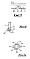
- the lamp holder 16 comprises a one-piece plastics moulding which has a lamp receiving part 20, integral lower legs 21 which straddle and are attached to the body 17 of the switch 15 and a central collar 22 which is cut away to define two arms 23 which extend circumferentially in opposite directions at diametrically opposed positions.
- Each arm 23 has a pin-shaped projection 24 extending radially outwardly at its free end.
- the arms are resiliently deflectable so that they tend to retain their circumferential shape but the free ends can be temporarily pushed radially inwardly by application of manual pressure.
- the inner end region of the cylindrical section 4 of the body part 2 is provided with diametrically opposed through holes 25 spaced by 90° from the gaps in the internal shoulder 13 and the feet 11.
- These holes 25 are closely spaced from the periphery of the cylindrical section 4 and are of very slightly greater diameter than the pin-shaped projections 24.
- the cylindrical section 4 has portions of reduced thickness 26 around the holes 25 extending up to the periphery of the section 4 so as to define straight-sided tapered channels on the internal surface of the cylindrical section 4 leading to the holes 25, such channels 26 being slightly wider than the diameter of the holes 25 and having scolloped edges 30 that allow easy alignment of the pins 24.
- the cylindrical section 4 of the body part 2 is pushed through the hole in the panel 1 and the body part 2 is fixed in position by means of an internally threaded annular member 27 which is screwed onto the cylindrical section 4 to clamp the panel 1 between the rim 5 and the member 27 (with an intervening washer 28).
- a lamp 29 is inserted into the lamp holder 20 and the lamp 29 and the lamp holder 20 are pushed into the inner end of the cylindrical section 4 with the pins 24 aligned with the channels 26.
- the arms 23 are deflected inwardly by engagement of the pins 24 with the internal surface of the cylindrical section 4 within the channels 26 whereby the lamp holder 20 can be pushed to a position at which the pins 24 snap-fit into the holes 25.
- the relative diameters of the lamp holder collar 22 and the internal surface of the cylindrical section 4 are such that the lamp holder 20 can be easily pushed in with the pins 24 aligned with the channels 26, but cannot be readily pushed in with the pins 24 aligned with thicker wall parts of the cylindrical section 4.
- the pins 24 are pushed into the holes 25 by the resilience of the arms 23 and are a close fit within the holes 25.
- the base structure 3 is therefore held in precise position circumferentially relative to the body part 2. In this position, the arrangement is such that the out turned end of one of the feet 11 is closely over the operating member 19 of the microswitch 15.
- the push button 7 can now be pushed to cause the slider element 8 to move within the cylindrical section 4 against the action of the spring 14 to cause the switch operating member 19 to be depressed. On release, the push button 7 is moved back by the spring 14.
- the base structure 3 can be removed from the body part 2 simply by pulling the lamp holder 20 out of the cylindrical section 4.
- the switch assembly and disassembly can be readily effected in a convenient manner, simply by moving the lamp holder 20 axially into and out of the body part 2.
- the base structure 3 is accurately located circumferentially relative to the body part 2 whereby reliable operation of the microswitch 15 can be assured.
Landscapes
- Push-Button Switches (AREA)
- Switches With Compound Operations (AREA)
- Keying Circuit Devices (AREA)
- Oscillators With Electromechanical Resonators (AREA)
- Electronic Switches (AREA)
Claims (15)
- Beleuchtete elektrische Druckknopfschalter-Baugruppe, aufweisend eine Basisstruktur (3), die einen Mikroschalter (15) und eine Lampenhalterung (16) enthält, sowie einen röhrenförmigen Körperteil (2), der dafür ausgelegt ist, an einem inneren Endbereich um die Lampenhalterung (16) herum zu passen, und der einen Druckknopf (7) an seinem gegenüber liegenden äußeren Endbereich sowie ein inneres Schiebeelement (8) besitzt, welches dafür ausgelegt ist, durch den Druckknopf (7) in Wirkverbindung mit dem Mikroschalter (15) gebracht zu werden, wobei die Basisstruktur (3) und der innere Endbereich des Körperteils (2) ineinander greifende Elemente enthalten, die eine lösbare Verbindung des Körperteils (2) und der Basisstruktur (3) bewirken, wobei die ineinander greifenden Elemente mindestens einen querlaufenden Vorsprung (24) umfassen, der mit einer entsprechenden Öffnung (25) in Eingriff gebracht werden kann, welche an der Basisstruktur (3) bzw. dem Körperteil (2) vorgesehen ist, wobei der Vorsprung (24) eng in der Öffnung (25) anliegt, rings um den röhrenförmigen Körperteil (2), dadurch gekennzeichnet, dass die aufnehmende Öffnung in einem axial verlaufenden ausgesparten Kanal angeordnet ist und, dass mindestens der Vorsprung (24) oder der innere Endbereich des Körperteils (2) in Querrichtung flexibel biegbar ist, um das axiale Zusammenfügen und Lösen in axialer Richtung durch Eindrücken bzw. Herausziehen der Basisstruktur und des Körperteils geführt durch den Kanal zu ermöglichen.
- Baugruppe gemäß Anspruch 1, dadurch gekennzeichnet, dass der Vorsprung (24) an der Basisstruktur (3) ausgebildet ist und die Öffnung (25) an dem Körperteil (2) ausgebildet ist.
- Baugruppe gemäß Anspruch 1 oder 2, dadurch gekennzeichnet, dass der Vorsprung (24) in Querrichtung flexibel biegbar ist.
- Baugruppe gemäß Anspruch 3, dadurch gekennzeichnet, dass der Vorsprung (24) an einem biegbaren Arm (23) ausgebildet ist.
- Baugruppe gemäß Anspruch 4, dadurch gekennzeichnet, dass sich der Arm (23) entlang des Umfangs erstreckt.
- Baugruppe gemäß einem der Ansprüche 1 bis 5, dadurch gekennzeichnet, dass die Öffnung (25) eine durchgehende Bohrung ist.
- Baugruppe gemäß einem der Ansprüche 1 bis 6, dadurch gekennzeichnet, dass sie zwei Vorsprünge (24) und zwei Öffnungen (25) besitzt.
- Baugruppe gemäß Anspruch 7, dadurch gekennzeichnet, dass die Vorsprünge (24) einander genau gegenüberliegen.
- Baugruppe gemäß Anspruch 8, sofern dieser abhängt von Anspruch 5, dadurch gekennzeichnet, dass sich die Arme in entgegengesetzten Richtungen erstrecken.
- Baugruppe gemäß einem der Ansprüche 1 bis 8, dadurch gekennzeichnet, dass eine Führungsanordnung (26) bereitgestellt wird, die die axiale Bewegung der Basisstruktur (3) in Bezug auf den Körperteil (2) steuert.
- Baugruppe gemäß einem der Ansprüche 1 bis 10, dadurch gekennzeichnet, dass der Körperteil (2) eine zylindrische Struktur (4) aufweist, die an ihrer äußeren Oberfläche mit einem Gewinde versehen ist und die ein passendes, an der Innenseite mit einem Gewinde versehenes ringförmiges Element (27) aufnimmt und die einen vergrößerten Kopf (5, 6) an ihrem äußeren Ende aufweist, um den Druckknopf (7) aufzunehmen und zu fixieren.
- Baugruppe gemäß einem der Ansprüche 1 bis 11, dadurch gekennzeichnet, dass das Schiebeelement (8) ein röhrenförmiges Element (9) umfasst, welches einander genau gegenüberliegende axial vorspringende Füße (10) besitzt, zur Wirkverbindung mit dem Mikroschalter (15).
- Baugruppe gemäß einem der Ansprüche 1 bis 12, dadurch gekennzeichnet, dass ein Federelement (14) zwischen dem Körperteil (2) und dem Schiebeelement (8) angeordnet ist.
- Baugruppe gemäß den Ansprüchen 12 und 13, dadurch gekennzeichnet, dass die Füße (10) nach außen gebogene Enden (11) haben, die mit dem Körperteil (2) in Eingriff gelangen, um den Hubweg des Schiebelements (8) zu begrenzen.
- Baugruppe gemäß einem der Ansprüche 1 bis 14, welche in einem Spielautomaten zum Einsatz kommt.
Applications Claiming Priority (2)
| Application Number | Priority Date | Filing Date | Title |
|---|---|---|---|
| GB9922382A GB2354638B (en) | 1999-09-23 | 1999-09-23 | Switch assemblies |
| GB9922382 | 1999-09-23 |
Publications (3)
| Publication Number | Publication Date |
|---|---|
| EP1087414A1 EP1087414A1 (de) | 2001-03-28 |
| EP1087414B1 true EP1087414B1 (de) | 2007-08-29 |
| EP1087414B8 EP1087414B8 (de) | 2007-10-10 |
Family
ID=10861360
Family Applications (1)
| Application Number | Title | Priority Date | Filing Date |
|---|---|---|---|
| EP00308278A Expired - Lifetime EP1087414B8 (de) | 1999-09-23 | 2000-09-21 | Schalteinrichtungen |
Country Status (5)
| Country | Link |
|---|---|
| EP (1) | EP1087414B8 (de) |
| AT (1) | ATE371943T1 (de) |
| DE (1) | DE60036175D1 (de) |
| ES (1) | ES2293887T3 (de) |
| GB (1) | GB2354638B (de) |
Cited By (1)
| Publication number | Priority date | Publication date | Assignee | Title |
|---|---|---|---|---|
| US8624141B2 (en) | 2010-09-30 | 2014-01-07 | HAPP Controls, Inc. | Illuminated button assembly |
Families Citing this family (2)
| Publication number | Priority date | Publication date | Assignee | Title |
|---|---|---|---|---|
| GB0201109D0 (en) * | 2002-01-18 | 2002-03-06 | Richardson Guy B | Light bulb holder |
| CN109216074B (zh) * | 2018-10-22 | 2023-08-22 | 宁波万事达综研电气有限公司 | 一种单刀单掷式跷板开关 |
Family Cites Families (7)
| Publication number | Priority date | Publication date | Assignee | Title |
|---|---|---|---|---|
| JPS61500993A (ja) * | 1983-12-21 | 1986-05-15 | アレン・ブラドリイ カンパニ | 改良された押釦スイッチおよびパイロット・ライト |
| ES2003022A6 (es) * | 1987-03-25 | 1988-10-01 | Romero Herrera Ricardo | Interruptor con pulsador y lampara incorporada |
| US4968860A (en) * | 1988-05-19 | 1990-11-06 | Omron Tateisi Electronics Co. | Light emitting type push button switch |
| GB8829804D0 (en) * | 1988-12-21 | 1989-02-15 | Aerial Pressings Limited | Improvements in or relating to push buttons |
| IT234069Y1 (it) * | 1994-03-16 | 2000-02-23 | Alberici S N C Di Augusto Albe | Dispositivo d'aggancio di un portalampada-portamicrointerruttore al corpo di un pulsante luminoso. |
| GB2310084A (en) * | 1996-02-12 | 1997-08-13 | Gamesman Ltd | Electrical switches |
| JP3644258B2 (ja) * | 1998-06-25 | 2005-04-27 | オムロン株式会社 | スイッチ |
-
1999
- 1999-09-23 GB GB9922382A patent/GB2354638B/en not_active Expired - Fee Related
-
2000
- 2000-09-21 ES ES00308278T patent/ES2293887T3/es not_active Expired - Lifetime
- 2000-09-21 EP EP00308278A patent/EP1087414B8/de not_active Expired - Lifetime
- 2000-09-21 DE DE60036175T patent/DE60036175D1/de not_active Expired - Lifetime
- 2000-09-21 AT AT00308278T patent/ATE371943T1/de active
Cited By (1)
| Publication number | Priority date | Publication date | Assignee | Title |
|---|---|---|---|---|
| US8624141B2 (en) | 2010-09-30 | 2014-01-07 | HAPP Controls, Inc. | Illuminated button assembly |
Also Published As
| Publication number | Publication date |
|---|---|
| EP1087414A1 (de) | 2001-03-28 |
| DE60036175D1 (de) | 2007-10-11 |
| ATE371943T1 (de) | 2007-09-15 |
| EP1087414B8 (de) | 2007-10-10 |
| ES2293887T3 (es) | 2008-04-01 |
| GB9922382D0 (en) | 1999-11-24 |
| GB2354638B (en) | 2003-07-16 |
| GB2354638A (en) | 2001-03-28 |
Similar Documents
| Publication | Publication Date | Title |
|---|---|---|
| US4419555A (en) | Illuminated push-button switch assembly | |
| US6310308B1 (en) | Compact push-button switch assembly | |
| US20070055298A1 (en) | Inssertion depth-adjustable needle insertion device | |
| EP2430712A1 (de) | Led-nachtlicht | |
| US6420667B1 (en) | Compound switch device | |
| EP1091374B1 (de) | Schalter | |
| US7554047B2 (en) | Lighted pushbutton-type switch assembly | |
| EP1811615B1 (de) | Sichere Lampenfassung und Verfahren für das Vermeiden eines unbeabsichtigten elektrischen Schlags verusacht durch die Lampenfassung | |
| US4404445A (en) | Pushbutton switch operator assembly | |
| EP0163782A1 (de) | Bedienungseinrichtung mit Druckknopf | |
| US20020125119A1 (en) | Push-button type electrical switch | |
| EP0276463B1 (de) | Vorrichtung zum Einstellen der Schalter und Regelvorrichtungen eines Haushaltgerätes | |
| US6987233B2 (en) | Push-button type electrical switch having secondary conductive pathway to ground | |
| EP1087414A1 (de) | Schalteinrichtungen | |
| US4791257A (en) | Key element for a contactless keyboard | |
| US6870114B2 (en) | Method and apparatus for removing and replacing bulb of push-button type electrical switch | |
| EP0080807A2 (de) | Anpassungsvorrichtung zum Aufbringen eines Schalters auf einer Platte | |
| EP1912231A2 (de) | Druckknopfschalter | |
| EP1143468B1 (de) | Schalteranordnung | |
| CN113454743B (zh) | 具有开关状态标识的按键开关配置 | |
| JP2006019130A (ja) | プッシュスイッチ | |
| WO1985002938A1 (en) | Push button switch and pilot light | |
| KR200295564Y1 (ko) | 푸쉬버튼 스위치 | |
| JP2004214101A (ja) | 操作ボタン装置 | |
| US4583154A (en) | Portable lamp with a fluorescent tube and a ballast tube |
Legal Events
| Date | Code | Title | Description |
|---|---|---|---|
| PUAI | Public reference made under article 153(3) epc to a published international application that has entered the european phase |
Free format text: ORIGINAL CODE: 0009012 |
|
| AK | Designated contracting states |
Kind code of ref document: A1 Designated state(s): AT BE CH CY DE DK ES FI FR GB GR IE IT LI LU MC NL PT SE |
|
| AX | Request for extension of the european patent |
Free format text: AL;LT;LV;MK;RO;SI |
|
| 17P | Request for examination filed |
Effective date: 20010409 |
|
| AKX | Designation fees paid |
Free format text: AT BE CH CY DE DK ES FI FR GB GR IE IT LI LU MC NL PT SE |
|
| GRAP | Despatch of communication of intention to grant a patent |
Free format text: ORIGINAL CODE: EPIDOSNIGR1 |
|
| GRAS | Grant fee paid |
Free format text: ORIGINAL CODE: EPIDOSNIGR3 |
|
| GRAA | (expected) grant |
Free format text: ORIGINAL CODE: 0009210 |
|
| AK | Designated contracting states |
Kind code of ref document: B1 Designated state(s): AT BE CH CY DE DK ES FI FR GB GR IE IT LI LU MC NL PT SE |
|
| REG | Reference to a national code |
Ref country code: GB Ref legal event code: FG4D |
|
| RBV | Designated contracting states (corrected) |
Designated state(s): AT BE CH CY DE DK ES FI FR GR IE IT LI LU MC NL PT SE |
|
| REG | Reference to a national code |
Ref country code: CH Ref legal event code: EP |
|
| REG | Reference to a national code |
Ref country code: IE Ref legal event code: FG4D |
|
| REF | Corresponds to: |
Ref document number: 60036175 Country of ref document: DE Date of ref document: 20071011 Kind code of ref document: P |
|
| PG25 | Lapsed in a contracting state [announced via postgrant information from national office to epo] |
Ref country code: NL Free format text: LAPSE BECAUSE OF FAILURE TO SUBMIT A TRANSLATION OF THE DESCRIPTION OR TO PAY THE FEE WITHIN THE PRESCRIBED TIME-LIMIT Effective date: 20070829 Ref country code: FI Free format text: LAPSE BECAUSE OF FAILURE TO SUBMIT A TRANSLATION OF THE DESCRIPTION OR TO PAY THE FEE WITHIN THE PRESCRIBED TIME-LIMIT Effective date: 20070829 |
|
| NLV1 | Nl: lapsed or annulled due to failure to fulfill the requirements of art. 29p and 29m of the patents act | ||
| PG25 | Lapsed in a contracting state [announced via postgrant information from national office to epo] |
Ref country code: CH Free format text: LAPSE BECAUSE OF FAILURE TO SUBMIT A TRANSLATION OF THE DESCRIPTION OR TO PAY THE FEE WITHIN THE PRESCRIBED TIME-LIMIT Effective date: 20070829 Ref country code: LI Free format text: LAPSE BECAUSE OF FAILURE TO SUBMIT A TRANSLATION OF THE DESCRIPTION OR TO PAY THE FEE WITHIN THE PRESCRIBED TIME-LIMIT Effective date: 20070829 |
|
| REG | Reference to a national code |
Ref country code: CH Ref legal event code: PL |
|
| PG25 | Lapsed in a contracting state [announced via postgrant information from national office to epo] |
Ref country code: BE Free format text: LAPSE BECAUSE OF FAILURE TO SUBMIT A TRANSLATION OF THE DESCRIPTION OR TO PAY THE FEE WITHIN THE PRESCRIBED TIME-LIMIT Effective date: 20070829 |
|
| REG | Reference to a national code |
Ref country code: ES Ref legal event code: FG2A Ref document number: 2293887 Country of ref document: ES Kind code of ref document: T3 |
|
| EN | Fr: translation not filed | ||
| PG25 | Lapsed in a contracting state [announced via postgrant information from national office to epo] |
Ref country code: MC Free format text: LAPSE BECAUSE OF NON-PAYMENT OF DUE FEES Effective date: 20070930 Ref country code: DE Free format text: LAPSE BECAUSE OF FAILURE TO SUBMIT A TRANSLATION OF THE DESCRIPTION OR TO PAY THE FEE WITHIN THE PRESCRIBED TIME-LIMIT Effective date: 20071201 Ref country code: DK Free format text: LAPSE BECAUSE OF FAILURE TO SUBMIT A TRANSLATION OF THE DESCRIPTION OR TO PAY THE FEE WITHIN THE PRESCRIBED TIME-LIMIT Effective date: 20070829 Ref country code: GR Free format text: LAPSE BECAUSE OF FAILURE TO SUBMIT A TRANSLATION OF THE DESCRIPTION OR TO PAY THE FEE WITHIN THE PRESCRIBED TIME-LIMIT Effective date: 20071130 |
|
| PG25 | Lapsed in a contracting state [announced via postgrant information from national office to epo] |
Ref country code: PT Free format text: LAPSE BECAUSE OF FAILURE TO SUBMIT A TRANSLATION OF THE DESCRIPTION OR TO PAY THE FEE WITHIN THE PRESCRIBED TIME-LIMIT Effective date: 20080129 |
|
| PG25 | Lapsed in a contracting state [announced via postgrant information from national office to epo] |
Ref country code: SE Free format text: LAPSE BECAUSE OF FAILURE TO SUBMIT A TRANSLATION OF THE DESCRIPTION OR TO PAY THE FEE WITHIN THE PRESCRIBED TIME-LIMIT Effective date: 20071129 |
|
| PLBE | No opposition filed within time limit |
Free format text: ORIGINAL CODE: 0009261 |
|
| STAA | Information on the status of an ep patent application or granted ep patent |
Free format text: STATUS: NO OPPOSITION FILED WITHIN TIME LIMIT |
|
| 26N | No opposition filed |
Effective date: 20080530 |
|
| PG25 | Lapsed in a contracting state [announced via postgrant information from national office to epo] |
Ref country code: IE Free format text: LAPSE BECAUSE OF NON-PAYMENT OF DUE FEES Effective date: 20070921 |
|
| PG25 | Lapsed in a contracting state [announced via postgrant information from national office to epo] |
Ref country code: FR Free format text: LAPSE BECAUSE OF NON-PAYMENT OF DUE FEES Effective date: 20070930 |
|
| PG25 | Lapsed in a contracting state [announced via postgrant information from national office to epo] |
Ref country code: CY Free format text: LAPSE BECAUSE OF FAILURE TO SUBMIT A TRANSLATION OF THE DESCRIPTION OR TO PAY THE FEE WITHIN THE PRESCRIBED TIME-LIMIT Effective date: 20070829 |
|
| PG25 | Lapsed in a contracting state [announced via postgrant information from national office to epo] |
Ref country code: LU Free format text: LAPSE BECAUSE OF NON-PAYMENT OF DUE FEES Effective date: 20070921 |
|
| PGFP | Annual fee paid to national office [announced via postgrant information from national office to epo] |
Ref country code: AT Payment date: 20130927 Year of fee payment: 14 |
|
| PGFP | Annual fee paid to national office [announced via postgrant information from national office to epo] |
Ref country code: IT Payment date: 20130925 Year of fee payment: 14 |
|
| PGFP | Annual fee paid to national office [announced via postgrant information from national office to epo] |
Ref country code: ES Payment date: 20131030 Year of fee payment: 14 |
|
| REG | Reference to a national code |
Ref country code: AT Ref legal event code: MM01 Ref document number: 371943 Country of ref document: AT Kind code of ref document: T Effective date: 20140921 |
|
| PG25 | Lapsed in a contracting state [announced via postgrant information from national office to epo] |
Ref country code: IT Free format text: LAPSE BECAUSE OF NON-PAYMENT OF DUE FEES Effective date: 20140921 Ref country code: AT Free format text: LAPSE BECAUSE OF NON-PAYMENT OF DUE FEES Effective date: 20140921 |
|
| REG | Reference to a national code |
Ref country code: ES Ref legal event code: FD2A Effective date: 20151028 |
|
| PG25 | Lapsed in a contracting state [announced via postgrant information from national office to epo] |
Ref country code: ES Free format text: LAPSE BECAUSE OF NON-PAYMENT OF DUE FEES Effective date: 20140922 |