EP1087485A1 - Elektrischer Kabelkanal mit weichem Scharnier - Google Patents
Elektrischer Kabelkanal mit weichem Scharnier Download PDFInfo
- Publication number
- EP1087485A1 EP1087485A1 EP00402568A EP00402568A EP1087485A1 EP 1087485 A1 EP1087485 A1 EP 1087485A1 EP 00402568 A EP00402568 A EP 00402568A EP 00402568 A EP00402568 A EP 00402568A EP 1087485 A1 EP1087485 A1 EP 1087485A1
- Authority
- EP
- European Patent Office
- Prior art keywords
- cover
- rib
- hinge
- groove
- edge
- Prior art date
- Legal status (The legal status is an assumption and is not a legal conclusion. Google has not performed a legal analysis and makes no representation as to the accuracy of the status listed.)
- Granted
Links
- 238000009429 electrical wiring Methods 0.000 title claims description 6
- 239000000853 adhesive Substances 0.000 claims abstract description 5
- 230000001070 adhesive effect Effects 0.000 claims abstract description 5
- 239000013536 elastomeric material Substances 0.000 claims abstract description 4
- 239000000463 material Substances 0.000 description 14
- 238000001125 extrusion Methods 0.000 description 9
- 238000000034 method Methods 0.000 description 4
- 239000013013 elastic material Substances 0.000 description 2
- 229940082150 encore Drugs 0.000 description 2
- 230000035939 shock Effects 0.000 description 2
- 238000012550 audit Methods 0.000 description 1
- 239000011324 bead Substances 0.000 description 1
- 238000005452 bending Methods 0.000 description 1
- 230000000694 effects Effects 0.000 description 1
- 230000002787 reinforcement Effects 0.000 description 1
Images



Classifications
-
- H—ELECTRICITY
- H02—GENERATION; CONVERSION OR DISTRIBUTION OF ELECTRIC POWER
- H02G—INSTALLATION OF ELECTRIC CABLES OR LINES, OR OF COMBINED OPTICAL AND ELECTRIC CABLES OR LINES
- H02G3/00—Installations of electric cables or lines or protective tubing therefor in or on buildings, equivalent structures or vehicles
- H02G3/02—Details
- H02G3/04—Protective tubing or conduits, e.g. cable ladders or cable troughs
- H02G3/0406—Details thereof
- H02G3/0418—Covers or lids; Their fastenings
Definitions
- the invention relates to a hinged electrical wiring duct flexible, mainly comprising two profiled elements, namely a bottom, the more often with a U-shaped profile and a shaped lid to snap on said bottom; it relates more particularly to an improvement relating to a flexible longitudinal hinge connecting the cover to a side wall of said bottom.
- US Patent No. 5,235,136 describes a wiring conduit of the defined kind above, in which the hinge is constituted by a thinning of material extending longitudinally on one side between the part forming said bottom and the part forming said cover.
- the edges of the bottom and cover are provided with means which fit together by force, taking advantage of the relative flexibility of the material used, generally a semi-rigid plastic.
- the hinge area is relatively deformable and the closed duct may accidentally open due to a frontal impact, on the cover, or side, on the bottom wall which includes said hinge.
- the prior document recommends provide a reinforcement inside the bottom, consisting of a longitudinal wing adjoining the bottom wall which comprises said hinge. This complicates the extrusion process of the profile constituting said conduit and limits the space available for wiring, inside this conduit.
- the invention allows overcome these disadvantages.
- the invention relates more particularly to an improvement making it possible to improve the locking of the cover in the closed position, especially in the event of a side impact.
- the invention relates to a wiring conduit electric comprising a bottom, preferably with a generally U-shaped profile and a cover shaped to snap onto said bottom, said cover being laterally attached to said bottom by a longitudinal hinge defined by a flexible and relatively deformable strip, characterized in that, said strip flexible extending flat against adjacent outer side faces of said bottom and said cover, it has a defined rib and groove, at vicinity of said hinge, on either side of the longitudinal direction of said strip, one of these two elements being integral with said bottom and the other being integral with said cover, said rib fitting into the groove at the closing the cover to establish a stiffening structure in the vicinity of said flexible strip.
- the rib and the groove can be shaped to ensure an open or at least ajar, stable position of the cover by report to said background.
- This stable position is for example ensured by a contact or bracing between the edge of the rib and an edge of the groove, intervening for a given position of the cover and which can be forced for the complete closure of the duct, taking advantage of the relative flexibility of the hinge.
- the hinge can be co-extruded with the cover and the background. It will for example be made of a different, more flexible material, or even somewhat elastic, for example by implementing a process of co-extrusion known per se.
- said hinge may consist of an attached adhesive strip.
- the conduit may include means for closing by interlocking force defined between the edges of the bottom and the cover opposite those adjoining said hinge, a first internal rib projecting from the inner face of said cover being positioned, when it is closed, near said closure means.
- This internal rib does not significantly complicate the extrusion of the lid.
- When closing it engages in said bottom and comes to stand near closing means. Therefore, it provides better locking of the locking means and an improvement in the resistance to shock in particular shocks directed in a direction perpendicular to a side wall of the duct and applying substantially at the level of the hinge flexible.
- a second internal rib projecting from the inside of the cover and coming to position when it is closed near the stiffening means.
- This second rib provides a better protection of the hinge, especially in relation to impact applying perpendicular to the longitudinal axis of the duct and parallel at its bottom.
- the stiffening means may include a rib and a defined groove in the vicinity of the hinge on either side of the steering longitudinal of the strip, one of these two elements being integral with the bottom and the other being secured to the cover.
- the rib fits into the groove, at the closing the cover.
- the rib of the stiffening means is part of the cover while the groove is part of the bottom.
- the stiffening means include an internal longitudinal boss extending near an edge of said bottom and said second internal rib preferably extends substantially along the entire height of this boss. The reverse is possible.
- the second internal rib has a folded edge engaging under this boss.
- first internal rib which can extend substantially along the entire height of a boss forming part of the closure means defined above.
- the first internal rib, integral with the cover, may also include a folded edge engaging under this boss.
- this first internal rib may be part of the closure means themselves.
- these closing means may have a first longitudinal shoulder defined externally at edge of the corresponding side wall of said bottom and constituting internally the longitudinal boss under which said first rib engages.
- the cover has a simple folded side edge coming to bear, in the closed position, on this first shoulder.
- the means of stiffening the flexible hinge can themselves be simplified as soon as the second internal rib has a folded edge engaging under the adjacent boss.
- said stiffening means comprise a second longitudinal shoulder defined at the edge of the corresponding side wall of said bottom and constituting internally the corresponding boss. Lid has side edge folded down coming to bear, in the closed position, on this second shoulder.
- the electrical wiring conduit 11 mainly consists of a bottom 12 with a profile generally U-shaped, with a cover 13 and a defined longitudinal hinge 15 by a flexible and relatively deformable strip 16, extending between the bottom and lid.
- the flexible strip 16 extends flat against the lateral faces adjacent exterior, said bottom 12 and said cover 13. It folds longitudinally at the opening.
- These three elements are represented in section transverse; they consist of extruded profiles and therefore have a invariable cross section. Description of the duct in cross section therefore suffices to characterize it.
- the cover 13 here has a section generally in U shape; it is shaped to force fit onto the bottom 12.
- said bottom consists of a flat wall 18, in strip shape, forming the base of the duct extended by two side walls 19, 20 extending longitudinally, generally perpendicular to the wall 18.
- the side wall 20 is attached to the cover 13 by the hinge 15 while that the opposite side wall 19 has a groove 21 shaped therein, opening longitudinally on its outer face.
- the cover 13 has an extended flat strip 22 longitudinally by two side walls 23, 24 generally perpendicular to the strip 22 and cooperating respectively with the side walls 19, 20 of the background.
- the side wall 23 has a re-entrant edge 26, bent at 90 °, provided for being able to engage in the longitudinal groove 21 of the side wall 19 of the bottom. Said longitudinal groove 21 and said re-entrant edge 26 form means of force-fitting closure. Interlocking is possible due to a sufficient flexibility of the side wall 19, in particular.
- the bottom and the cover at least are preferably made of semi-rigid plastic, like most wiring conduits commercially available, this material suitable for this type of closure by force fitting.
- the flexible strip 16 which constitutes the hinge is made of a material much more deformable than the bottom and the cover, or even a slightly elastic material, for example an elastomeric material.
- the strip 16 constituting the hinge 15 is co-extruded at the same time as the bottom and the cover, by using a bi-material co-extrusion process, known per se.
- the conduit 11 is therefore formed in a single extrusion operation.
- the conduit 11 has a rib 29 and a groove 30 defined on either side of the longitudinal direction of the strip 16 constituting said hinge.
- the rib 29 is part of the cover while the groove 30 is part of the bottom.
- the reverse is possible.
- the rib 29 consists of a re-entrant edge of the cover 13 while the groove 30 is shaped along a re-entrant edge of the background.
- the inside edge of the cover extends at the end of the side wall 24 to which is connected to said hinge while the inside edge of the bottom extends to the end of the side wall 20 of the bottom to which the same hinge. These two inside edges are oriented substantially at 45 ° towards the inside of the walls which carry them, respectively.
- the groove 30 has a hook-shaped profile open opposite the path of the inside edge of the cover, when closing the latter.
- Figures 4 and 5 illustrate another embodiment where the structural elements similar to those of Figures 1 to 3 bear the same reference numerals with the letter a in subscript.
- the closure means by force fitting defined opposite the hinge comprise a longitudinal groove 21a opening to the outside of the side wall of the bottom and a reentrant edge 26 a (90 °).
- the upper edge of the side wall 19 a and said reentrant edge 26 a are rounded to facilitate the nesting force, upon closing.
- the side of the strip 16 has forming the hinge 15a, the rib 29a of the cover part is attached to a side wall 24a of the lid substantially perpendicularly thereto (it forms a kind of hook in cross-section). It is shaped to engage in a groove 30 a substantially U profile attached laterally, here near its base, to a longitudinal edge of the side wall 20 to the bottom.
- the inner wing 32 a of the groove is slightly bent outward while the outer wing 33 a is less than the inner wing height.
- the hinge is in a material relatively softer and more flexible than the material making up the bottom and lid. The whole is obtained by bi-material co-extrusion.
- the rib and the groove are shaped to define a stable position ajar of the cover. This position is shown in Figure 4. In this position, the edge of the rib 29 is supported on the edge of the outer flange 33a of the groove. However, if the cover is forced towards its closed position, a slight extension of the hinge causes the rib to fit into the groove until the position illustrated in FIG. 5 is obtained.
- FIGS. 6 and 7 illustrate yet another embodiment, currently preferred, where the elements of similar structure bear the same reference numerals with the index b .
- the bottom 12 b has a flat wall 18 b in the form of a strip forming the base of the duct and two side walls 19 b , 20 b extending longitudinally, generally perpendicular to the wall 18 b .
- the cover 13 b comprises a strip 22 b extended longitudinally by two side walls 23 b , 24 b approximately perpendicular to the strip 22 b and cooperating respectively with the side walls 19 b , 20 b at the bottom.
- the side walls 19 b, 20 b of the bottom are similar and symmetrical with respect to a median plane of the conduit. It is the same for the side walls 23 b , 24 b of the cover.
- the hinge 15 b is attached to the walls 20 b , 24 b of the bottom and of the cover which are in the extension of one another, on one side of the duct when the cover is fitted on said duct (figure 7).
- the hinge 15 b consists of an adhesive strip.
- the side wall of the duct has a longitudinal groove 21 b opening on the outside face of this side wall while the corresponding end of the side wall 23 b of the cover has a re-entrant edge 26 b at 90 ° , shaped to engage in this longitudinal groove.
- the longitudinal groove 21 b and the re-entrant edge 26 b form means for closing by force fitting, thanks in particular to the flexibility of the side wall 19 b .
- the edge of the side wall of the bottom has a rounded bead 36 b which facilitates the nesting by force of the cover on the bottom.
- the arrangement is similar, that is to say that the side wall has a groove which constitutes the groove 30b of said stiffening structure while the end of the side wall of the cover has a edge returning at 90 ° which constitutes said rib 29 b of the stiffening structure.
- the stable half-open position of the cover is obtained when the end of the re-entrant edge meets the side wall 20b of the bottom, in the immediate vicinity of said groove 30b . This is visible in Figure 6.
- the bottom 12 c , the cover 13 c and the hinge 15 c are co-extruded, as explained with reference to the previous embodiment.
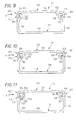
- the conduit of electrical wiring 111 mainly consists of a bottom 112 with profile generally U-shaped, with a cover 113 and a longitudinal hinge 115 defined by a flexible and relatively deformable strip 116, extending laterally between the bottom and the cover.
- the band flexible 116 extends flat between adjacent external lateral faces of the bottom 112 and cover 113.
- the material used to constitute the bottom and the cover is a semi-rigid plastic, susceptible to deformation momentarily under the effect of a constraint.
- the duct and the cover are shaped to fit together by force.
- the bottom consists of a flat wall 118 in the form of tape, forming the base of the conduit and this base is extended by two side walls 119, 120, extending longitudinally parallel one to the other, that is to say generally perpendicular to the wall 118.
- the wall side 120 is attached to the cover 113 by the hinge 115.
- the wall opposite side 119 has a shaped edge to cooperate with the edge matching, free, cover. In other words, closing means by force fitting 121 are defined between the edges of the bottom and of the cover opposite those next to hinge 115.
- stiffening means 125 are provided in the vicinity of the flexible strip 116 by the cooperation of structural elements integral with the bottom and lid, respectively.
- the cover 113 comprises a flat strip 122 extended longitudinally by two side walls 123, 124, overall perpendicular to the strip 122 and cooperating respectively with the walls side 119, 120 from the bottom.
- the side wall 123 has a re-entrant edge 126, bent at 90 °, provided to be able to engage in a longitudinal groove 127 of the side wall 119 the bottom.
- This longitudinal groove 127 and the re-entrant edge 126 form said means for closing by force fitting 121. Interlocking is possible due to sufficient flexibility of the side wall 119, in particular.
- the closure means create a first internal longitudinal boss 128, that is to say extending along the edge of said bottom, inside thereof.
- the flexible strip 116 which constitutes the hinge is produced in a much more deformable material than the bottom and the cover, or even a slightly elastic material, for example an elastomeric material.
- the strip 116 can be co-extruded at the same time as the bottom and the cover, by implementing a bi-material co-extrusion process, known in oneself.
- the conduit 111 can therefore be formed in a single extrusion operation.
- the stiffening means 125 are defined in the vicinity of the flexible strip by structural elements cooperating in the closing of the cover. It's about a rib 129 and a groove 130 defined along the longitudinal direction of the strip 116 constituting the hinge. In the example, the rib 129 is part of the cover while the groove 130 is part of the bottom.
- the rib 129 When the cover, the rib 129 is embedded in the groove 130 to establish a rigid protection around the flexible strip 116.
- the rib 129 consists of a re-entrant edge of the cover 113 while the groove 130 is shaped along an inside edge of the bottom.
- the inside edge of the cover extends to the end of the side wall 124 at which said hinge is connected while said edge coming from the bottom extends to the end of the side wall 120 of the bottom to which the same is connected hinge.
- stiffening means form a second boss longitudinal internal 132 (i.e. protruding longitudinally inside of the duct).
- a first internal rib 134 projects from the inner face of the cover and is positioned, when the latter is closed, near the closure means 121 defined above.
- the presence of this internal rib 134 ensures better locking of the closing means and above all an improvement in the impact resistance in the direction of the arrow F indicated in FIG. 9.
- the first inner rib 134 may extend substantially along the entire first boss.
- a second internal rib 136 makes protrusion from the inside of the cover and is positioned when the the latter near the stiffening means 125.
- the second inner rib 136a extends substantially along the entire height of said second boss. It also has an edge curved outward and engaging under the second boss.
- the first inner rib 134a extends substantially along the entire first boss 128 and also comprises a curved edge outwardly, engaging under the boss.
- the closing means 121 a like the stiffening means 125 a are simplified and, in particular, said first internal rib 134 b forms part of the closing means.
- the latter comprise a first longitudinal shoulder 140 (which replaces the groove) defined externally at the edge of the corresponding side wall 119 of said bottom.
- This first longitudinal shoulder internally forms said first longitudinal boss 128 a .
- the cover is simplified in this embodiment. It has a simple folded side edge 142 which comes to bear, in the closed position of the cover on said first shoulder.
- said first inner rib 134 b must have a curved edge (outwardly) engaging under said first boss 128 has, as said first rib is part of said closure means.
- the stiffening means 125 a comprise a second longitudinal shoulder 145 defined externally at the edge of the corresponding side wall 120 of the bottom and internally forming said second boss 132 a .
- the second internal rib 136 b has a curved edge engaging under the second boss 132 a .
- the cover also has on this side a simple folded side edge 148 which comes to bear, in the closed position of the cover, on said second shoulder 145.
- hinge 116 may consist of an adhesive strip attached to the side walls of the bottom and cover. In this case, the bottom and the cover are extruded separately and there is no need to use bi-material extrusion equipment.
Landscapes
- Engineering & Computer Science (AREA)
- Architecture (AREA)
- Civil Engineering (AREA)
- Structural Engineering (AREA)
- Details Of Indoor Wiring (AREA)
Applications Claiming Priority (4)
| Application Number | Priority Date | Filing Date | Title |
|---|---|---|---|
| FR9911953A FR2799057B1 (fr) | 1999-09-24 | 1999-09-24 | Conduit de cablage electrique a charniere souple |
| FR9911953 | 1999-09-24 | ||
| FR0004711 | 2000-04-12 | ||
| FR0004711A FR2807879B1 (fr) | 2000-04-12 | 2000-04-12 | Conduit de cablage electrique a charniere souple |
Publications (2)
| Publication Number | Publication Date |
|---|---|
| EP1087485A1 true EP1087485A1 (de) | 2001-03-28 |
| EP1087485B1 EP1087485B1 (de) | 2008-09-03 |
Family
ID=26212340
Family Applications (1)
| Application Number | Title | Priority Date | Filing Date |
|---|---|---|---|
| EP20000402568 Expired - Lifetime EP1087485B1 (de) | 1999-09-24 | 2000-09-18 | Elektrischer Kabelkanal mit weichem Scharnier |
Country Status (5)
| Country | Link |
|---|---|
| EP (1) | EP1087485B1 (de) |
| BR (1) | BR0004501A (de) |
| CA (1) | CA2319846A1 (de) |
| DE (1) | DE60040127D1 (de) |
| ES (1) | ES2313875T3 (de) |
Cited By (1)
| Publication number | Priority date | Publication date | Assignee | Title |
|---|---|---|---|---|
| US7099551B2 (en) * | 2001-08-30 | 2006-08-29 | Paul Hallinan | Cabling apparatus |
Families Citing this family (1)
| Publication number | Priority date | Publication date | Assignee | Title |
|---|---|---|---|---|
| CN112038992A (zh) * | 2020-09-08 | 2020-12-04 | 贾思宇 | 一种外墙装饰型通用电缆槽 |
Citations (3)
| Publication number | Priority date | Publication date | Assignee | Title |
|---|---|---|---|---|
| EP0526024A1 (de) * | 1991-07-24 | 1993-02-03 | Dek, Inc. | Wiederverschliessbares einteiliges Kabel- und Draht-Schutzrohr |
| DE29507233U1 (de) * | 1995-04-29 | 1995-09-07 | Stewing Kunststoffbetrieb Gmbh Dorsten, 46282 Dorsten | Kabelkanal |
| EP0809338A2 (de) * | 1996-05-22 | 1997-11-26 | Dek, Inc. | Wiederverschliessbarer Deckel für Kabel- und Leitungskanal |
-
2000
- 2000-09-18 EP EP20000402568 patent/EP1087485B1/de not_active Expired - Lifetime
- 2000-09-18 DE DE60040127T patent/DE60040127D1/de not_active Expired - Lifetime
- 2000-09-18 ES ES00402568T patent/ES2313875T3/es not_active Expired - Lifetime
- 2000-09-21 CA CA 2319846 patent/CA2319846A1/fr not_active Abandoned
- 2000-09-25 BR BR0004501A patent/BR0004501A/pt not_active IP Right Cessation
Patent Citations (4)
| Publication number | Priority date | Publication date | Assignee | Title |
|---|---|---|---|---|
| EP0526024A1 (de) * | 1991-07-24 | 1993-02-03 | Dek, Inc. | Wiederverschliessbares einteiliges Kabel- und Draht-Schutzrohr |
| US5235136A (en) * | 1991-07-24 | 1993-08-10 | Dek, Inc. | One-piece reclosable cable and wire duct |
| DE29507233U1 (de) * | 1995-04-29 | 1995-09-07 | Stewing Kunststoffbetrieb Gmbh Dorsten, 46282 Dorsten | Kabelkanal |
| EP0809338A2 (de) * | 1996-05-22 | 1997-11-26 | Dek, Inc. | Wiederverschliessbarer Deckel für Kabel- und Leitungskanal |
Cited By (1)
| Publication number | Priority date | Publication date | Assignee | Title |
|---|---|---|---|---|
| US7099551B2 (en) * | 2001-08-30 | 2006-08-29 | Paul Hallinan | Cabling apparatus |
Also Published As
| Publication number | Publication date |
|---|---|
| DE60040127D1 (de) | 2008-10-16 |
| EP1087485B1 (de) | 2008-09-03 |
| BR0004501A (pt) | 2001-06-19 |
| CA2319846A1 (fr) | 2001-03-24 |
| ES2313875T3 (es) | 2009-03-16 |
Similar Documents
| Publication | Publication Date | Title |
|---|---|---|
| FR2799057A1 (fr) | Conduit de cablage electrique a charniere souple | |
| EP0354082B1 (de) | Führungskulisse für bewegliche Fensterscheiben, insbesondere für Automobilfensterscheiben | |
| EP1263104B1 (de) | Winkelzubehörelement für Führungskanal | |
| EP0343046A1 (de) | Abdichtung, insbesondere für eine verschiebbare Fensterscheibe eines Kraftfahrzeuges | |
| EP1276197A1 (de) | Zusatz für Kabelrinnen mit Abschnitten unterschiedlicher Höhe | |
| EP0482999B1 (de) | Ansatzstück für Profilteil zum Beispiel Dichtungsprofil für Fahrzeugschiebefenster | |
| EP0755638A1 (de) | Behälter mit einem Klappdeckel und einem flexible Teile enthaltendem Scharnier | |
| FR2807879A1 (fr) | Conduit de cablage electrique a charniere souple | |
| EP0908992B1 (de) | Vorrichtung zur variablen Abdeckung von elektrischen kabelführungen | |
| EP2481875B1 (de) | Dichtung für Öffnungsflügel, und mit einer solchen Dichtung ausgestatteter Öffnungsflügel | |
| EP1087485A1 (de) | Elektrischer Kabelkanal mit weichem Scharnier | |
| EP2278109A2 (de) | Öffnungselement eines Verschlussrahmens, das Mittel gegen das Herausrutschen des Ausfachungselements enthält | |
| FR2813624A1 (fr) | Profile de raccord et d'etancheite, dispositif de raccord, panneau a structure sandwich, et ensemble de facade, de cloison ou de couverture | |
| EP0284522A1 (de) | Einbruchhemmendes Vorsatzfenster | |
| EP0038229A1 (de) | Scharnier zum Verbinden zweier Paneele, insbesondere zum Verbinden eines drehbaren Paneels mit einem feststehenden Paneel | |
| FR2857791A1 (fr) | Accessoire pour goulotte a verrouillage automatique | |
| EP0558390A1 (de) | Profillamelle für einen Vorhang und entsprechender Vorhang | |
| EP1432091B1 (de) | Kupplungsgarnitur für einen Kabelrinnesockel | |
| EP0658661B1 (de) | Leiste für die Verbindung einer Trennwand am Boden | |
| EP1120302A1 (de) | Rahmenanordnung für Glas oder Fenster, fest oder mobil | |
| FR2514731A1 (fr) | Recipient a couvercle tel que pot | |
| EP1313191B1 (de) | Zusatz für Kabelrinnen mit Klebmitteln fur Verbindung auf einem Deckelsabschnitt | |
| FR2900218A1 (fr) | Connecteur pour raccorder deux extremites creuses de profile | |
| EP1246333A1 (de) | Endstück für einen Führungskanal | |
| FR2767553A1 (fr) | Perfectionnement apporte a un element de chassis de porte ou fenetre a frappe |
Legal Events
| Date | Code | Title | Description |
|---|---|---|---|
| PUAI | Public reference made under article 153(3) epc to a published international application that has entered the european phase |
Free format text: ORIGINAL CODE: 0009012 |
|
| AK | Designated contracting states |
Kind code of ref document: A1 Designated state(s): DE ES FR GB IT SE |
|
| AX | Request for extension of the european patent |
Free format text: AL;LT;LV;MK;RO;SI |
|
| 17P | Request for examination filed |
Effective date: 20010410 |
|
| AKX | Designation fees paid |
Free format text: DE ES FR GB IT SE |
|
| GRAP | Despatch of communication of intention to grant a patent |
Free format text: ORIGINAL CODE: EPIDOSNIGR1 |
|
| RIN1 | Information on inventor provided before grant (corrected) |
Inventor name: ALBERT, CHRISTOPHE Inventor name: BONNASSIEUX, VINCENT Inventor name: MARCOU, JEAN-CLAUDE |
|
| GRAS | Grant fee paid |
Free format text: ORIGINAL CODE: EPIDOSNIGR3 |
|
| GRAA | (expected) grant |
Free format text: ORIGINAL CODE: 0009210 |
|
| AK | Designated contracting states |
Kind code of ref document: B1 Designated state(s): DE ES FR GB IT SE |
|
| REG | Reference to a national code |
Ref country code: GB Ref legal event code: FG4D Free format text: NOT ENGLISH |
|
| REF | Corresponds to: |
Ref document number: 60040127 Country of ref document: DE Date of ref document: 20081016 Kind code of ref document: P |
|
| REG | Reference to a national code |
Ref country code: SE Ref legal event code: TRGR |
|
| REG | Reference to a national code |
Ref country code: ES Ref legal event code: FG2A Ref document number: 2313875 Country of ref document: ES Kind code of ref document: T3 |
|
| PLBE | No opposition filed within time limit |
Free format text: ORIGINAL CODE: 0009261 |
|
| STAA | Information on the status of an ep patent application or granted ep patent |
Free format text: STATUS: NO OPPOSITION FILED WITHIN TIME LIMIT |
|
| 26N | No opposition filed |
Effective date: 20090604 |
|
| PGFP | Annual fee paid to national office [announced via postgrant information from national office to epo] |
Ref country code: SE Payment date: 20100818 Year of fee payment: 11 |
|
| REG | Reference to a national code |
Ref country code: SE Ref legal event code: EUG |
|
| PGFP | Annual fee paid to national office [announced via postgrant information from national office to epo] |
Ref country code: GB Payment date: 20120917 Year of fee payment: 13 |
|
| PGFP | Annual fee paid to national office [announced via postgrant information from national office to epo] |
Ref country code: ES Payment date: 20120822 Year of fee payment: 13 |
|
| PG25 | Lapsed in a contracting state [announced via postgrant information from national office to epo] |
Ref country code: SE Free format text: LAPSE BECAUSE OF NON-PAYMENT OF DUE FEES Effective date: 20110919 |
|
| PGFP | Annual fee paid to national office [announced via postgrant information from national office to epo] |
Ref country code: DE Payment date: 20130926 Year of fee payment: 14 |
|
| PGFP | Annual fee paid to national office [announced via postgrant information from national office to epo] |
Ref country code: IT Payment date: 20130920 Year of fee payment: 14 |
|
| GBPC | Gb: european patent ceased through non-payment of renewal fee |
Effective date: 20130918 |
|
| PG25 | Lapsed in a contracting state [announced via postgrant information from national office to epo] |
Ref country code: GB Free format text: LAPSE BECAUSE OF NON-PAYMENT OF DUE FEES Effective date: 20130918 |
|
| REG | Reference to a national code |
Ref country code: ES Ref legal event code: FD2A Effective date: 20141015 |
|
| PG25 | Lapsed in a contracting state [announced via postgrant information from national office to epo] |
Ref country code: ES Free format text: LAPSE BECAUSE OF NON-PAYMENT OF DUE FEES Effective date: 20130919 |
|
| REG | Reference to a national code |
Ref country code: DE Ref legal event code: R119 Ref document number: 60040127 Country of ref document: DE |
|
| REG | Reference to a national code |
Ref country code: DE Ref legal event code: R119 Ref document number: 60040127 Country of ref document: DE Effective date: 20150401 |
|
| PG25 | Lapsed in a contracting state [announced via postgrant information from national office to epo] |
Ref country code: DE Free format text: LAPSE BECAUSE OF NON-PAYMENT OF DUE FEES Effective date: 20150401 |
|
| PG25 | Lapsed in a contracting state [announced via postgrant information from national office to epo] |
Ref country code: IT Free format text: LAPSE BECAUSE OF NON-PAYMENT OF DUE FEES Effective date: 20140918 |
|
| REG | Reference to a national code |
Ref country code: FR Ref legal event code: PLFP Year of fee payment: 16 |
|
| REG | Reference to a national code |
Ref country code: FR Ref legal event code: PLFP Year of fee payment: 17 |
|
| PGFP | Annual fee paid to national office [announced via postgrant information from national office to epo] |
Ref country code: FR Payment date: 20160928 Year of fee payment: 17 |
|
| REG | Reference to a national code |
Ref country code: FR Ref legal event code: ST Effective date: 20180531 |
|
| PG25 | Lapsed in a contracting state [announced via postgrant information from national office to epo] |
Ref country code: FR Free format text: LAPSE BECAUSE OF NON-PAYMENT OF DUE FEES Effective date: 20171002 |