EP1087501A2 - Moteur/générateur avec plusieurs rotors - Google Patents
Moteur/générateur avec plusieurs rotors Download PDFInfo
- Publication number
- EP1087501A2 EP1087501A2 EP00120941A EP00120941A EP1087501A2 EP 1087501 A2 EP1087501 A2 EP 1087501A2 EP 00120941 A EP00120941 A EP 00120941A EP 00120941 A EP00120941 A EP 00120941A EP 1087501 A2 EP1087501 A2 EP 1087501A2
- Authority
- EP
- European Patent Office
- Prior art keywords
- core
- motor
- generator
- coils
- rotor
- Prior art date
- Legal status (The legal status is an assumption and is not a legal conclusion. Google has not performed a legal analysis and makes no representation as to the accuracy of the status listed.)
- Granted
Links
- 239000002131 composite material Substances 0.000 claims abstract description 10
- 230000002093 peripheral effect Effects 0.000 claims description 21
- 229910000831 Steel Inorganic materials 0.000 claims description 6
- 239000010959 steel Substances 0.000 claims description 6
- 239000002826 coolant Substances 0.000 claims description 2
- 239000007788 liquid Substances 0.000 claims description 2
- 238000006073 displacement reaction Methods 0.000 description 5
- 230000004907 flux Effects 0.000 description 4
- 230000000694 effects Effects 0.000 description 3
- 238000007373 indentation Methods 0.000 description 3
- 239000000696 magnetic material Substances 0.000 description 3
- 230000003014 reinforcing effect Effects 0.000 description 3
- 238000010586 diagram Methods 0.000 description 2
- 238000006243 chemical reaction Methods 0.000 description 1
- 238000010276 construction Methods 0.000 description 1
- 230000005347 demagnetization Effects 0.000 description 1
- 230000006866 deterioration Effects 0.000 description 1
- 230000004048 modification Effects 0.000 description 1
- 238000012986 modification Methods 0.000 description 1
- 230000000717 retained effect Effects 0.000 description 1
- 238000004804 winding Methods 0.000 description 1
Images



Classifications
-
- H—ELECTRICITY
- H02—GENERATION; CONVERSION OR DISTRIBUTION OF ELECTRIC POWER
- H02K—DYNAMO-ELECTRIC MACHINES
- H02K17/00—Asynchronous induction motors; Asynchronous induction generators
- H02K17/02—Asynchronous induction motors
-
- H—ELECTRICITY
- H02—GENERATION; CONVERSION OR DISTRIBUTION OF ELECTRIC POWER
- H02M—APPARATUS FOR CONVERSION BETWEEN AC AND AC, BETWEEN AC AND DC, OR BETWEEN DC AND DC, AND FOR USE WITH MAINS OR SIMILAR POWER SUPPLY SYSTEMS; CONVERSION OF DC OR AC INPUT POWER INTO SURGE OUTPUT POWER; CONTROL OR REGULATION THEREOF
- H02M7/00—Conversion of AC power input into DC power output; Conversion of DC power input into AC power output
Definitions
- This invention relates to a motor/generator provided with a plurality of rotors.
- Tokkai-Hei-8-340663 published by the Japanese Patent Office in 1996 discloses a motor/generator having one stator and two rotors.
- the stator and rotors are disposed co-axially, one rotor being arranged on the inner side of the stator while the other rotor is disposed on the outer side of the stator.
- the stator is provided with an independent group of coils for each rotor. Two groups of coils respectively drive the rotors by producing two different rotating magnetic fields.
- the motor/generator In order to supply power currents of different waveforms to the two groups of coils, the motor/generator has two inverters. Accordingly, the construction of the motor/generator is complicated and the switching loss in the inverters is also large. Furthermore the overlapping disposition of the rotors on the inner and outer sides of the stator results in the stator requiring a cantilever support structure which has low structural stability.
- this invention provides a motor/generator comprising a first rotation shaft, a second rotation shaft, a first rotor, a second rotor, a stator and a current control device.
- the first rotor rotates with the first rotation shalt and has a first number of magnetic poles that form a first magnetic field.
- the second rotation shaft rotates relative to the first rotation shaft and is supported co-axially with the first rotation shalt.
- the second rotor rotates with the second rotation shaft and has a second number of magnetic poles that form a second magnetic field. The first number and the second number are different.
- the first rotor and the second rotor are disposed in series along the first rotation shaft.
- the stator comprises coils that generate a first rotating magnetic field in synchronism with the first magnetic field by application of a first alternating current, and generate a second rotating magnetic field in synchronism with the second magnetic field by application of a second alternating current.
- the current control device supplies a composite current comprising the first alternating current and the second alternating current to the coils.
- This invention also provides a motor/generator comprising a first rotation shalt, a second rotation shalt, a first rotor, a second rotor, a first stator, a second stator and a current control device.
- the first rotor rotates with the first rotation shaft and has a first number of magnetic poles that form a first magnetic field.
- the second rotation shaft rotates relative to the first rotation shaft.
- the second rotation shaft and the first rotation shaft have different rotation axes.
- the second rotor rotates with the second rotation shaft and has a second number of magnetic poles that form a second magnetic field.
- the first number and the second number are different.
- the first stator comprises a third number of first coils that generate a first rotating magnetic field in synchronism with the first magnetic field by application of a first alternating current.
- the second stator comprises a fourth number of second coils that generate a rotating magnetic field in synchronism with second magnetic field by application of a second alternating current.
- the third number is equal to the fourth number.
- the current control device supplies a composite current comprising the first alternating current and the second alternating current to both the first coils and the second coils.
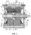
- a motor/generator according to this invention is provided with a stator 14, a first rotor 2 and a second rotor 3.
- the first rotor 2 is provided with a rotation shaft 4 and the second rotor 3 Is provided with a rotation shaft 5.
- the rotation shaft 4 has a cylindrical shape and the rotation shaft 5 is fitted through the rotation shaft 4.
- the rotation shafts 4 and 5 are disposed co-axially.
- the inner periphery of both ends of the rotation shaft 5 is supported by the rotation shaft 4 through needle bearings 30A and 30B.
- the outer periphery of one end of the rotation shaft 4 is supported on the case 1 through a ball bearing 31.
- the outer periphery of one end of the rotation shaft 5, positioned opposite the ball bearing 31, is supported on the case 1 by a ball bearing 32.
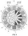
- the first rotor 2 comprises six magnets 6.
- the second rotor comprises eight magnets 7.
- the number of magnets of the first rotor 2 and the second rotor 3 is not limited to the above number.
- the stator 14 comprises twelve cores 11 which are disposed to cover the outer periphery of the first rotor 2 and the second rotor 3. Each core 11 is made of magnetic plate members laminated in the direction of the rotation shaft 5. A slot 15 is formed between adjacent cores 11 to provide a space for stator coils 16 that are wound on the cores 11.
- the stator 14 is fitted inside the cylindrical case 1. Displacement of the cores 11 towards outer side is prevented by the case 1. Retaining plates 18 parallel to the rotation shaft 5 are disposed between each core 11.
- a total of twelve retaining plates 18 are disposed on a circumferential periphery. Ring grooves 23 and 24 which are formed on rings 21 and 22 are press fitted inside both ends of these retaining plates 18.
- the retaining plates both ends of which are thus retained by the ring rings 21 and 22 prevent the cores 11 from displacing to the inner side.
- the inner periphery of the cores 11 is also supported by a reinforcing ring 25 disposed between the first rotor 2 and the second rotor 3.
- the outer peripheral sections of adjacent cores 11 are in contact.
- the inner peripheral sections of the cores 11 project inwardly independently with stator coils 16 wound onto the projecting portions.
- the stator 14 by supplying a first multi-phase alternating current having a phase difference of 90 degrees and a frequency determined by a required rotation speed of the first rotor 2, to the twelve stator coils 16, the stator 14 generates a first rotating magnetic field which has three pairs of magnetic poles and which synchronously rotates the first rotor 2 at the required rotation speed.
- the stator 14 by supplying a second multi-phase alternating current having a phase difference of 120 degrees and a frequency determined by a required rotation speed of the second rotor 3, to the twelve stator coils 16, the stator 14 generate a second rotating magnetic field which has four pairs of magnetic poles and synchronously rotates the second rotor 3.
- stator 14 simultaneously generates the first and second rotating magnetic fields which respectively rotate the first and second rotors 2, 3.
- the motor is provided with a battery 111, an inverter 112 and a control unit 115 in order to supply a composite alternating current to the stator coils 16.
- the inverter 112 may be obtained by expanding a normal three-phase bridge-type inverter into twelve phase and is provided with twelve output terminals. Each output terminal is connected respectively with twelve stator coils 16. The end of each stator coil 16 is connected to a terminating point 16A.
- the sum of the instantaneous current at the terminating point 16A is always zero.
- the inverter 112 comprises twenty-four transistors and the same number of diodes, and a pulse width modulation (PWM) signal from the control unit 115 is input to the base of each transistor.
- PWM pulse width modulation
- Signals are input into the control unit 115 from a rotation angle sensor 113 detecting a rotation position of the first rotor 2 and a rotation angle sensor 114 detecting a rotation position of the second rotor 3.
- the rotation angle sensors 113 and 114 are formed by a rotary encoder or a resolver.
- the rotational torque required by the first rotor 2 and the second rotor 3 is input to the control unit 115 as a command signal.
- the control unit 115 outputs the PWM signals to the inverter 112 based on the command signal and the rotational positions of the first rotor 2 and the second rotor 3.
- this motor/generator drives the two rotors 2 and 3 with one inverter 112 and one stator 14, it is possible to reduce the capacitance of the transistors in comparison with a motor/generator having two inverters and stators to drive two rotors. Reduced switching loss is attained as a result.
- This invention may also be applied to a case where one of the first rotor 2 and the second rotor 3 serves as a generator for generating power while the other rotor serves as a motor rotating by the generated power.
- a current corresponding to the difference of the motor driving current and the generated current is supplied to the stator coils 16 from the inverter 112.
- This electric power management much improves electrical efficiency of the motor/generator compared with the conventional electric power management in which power generated by a generator is once stored in a battery and a motor is driven by the power supplied from the battery.
- first rotor 2 and the second rotor 3 are disposed In series along the rotation shaft 5 and the stator 14 is disposed on an outer side of the rotors 2 and 3, the stator 14 can be firmly secured to the case 1.
- first rotor 2 and the second rotor 3 are supported in a stable manner with respect to high velocity rotation since the needle bearings 30A and 30B and the ball bearings 31 and 32 support both ends of the rotation shafts 4 and 5.
- the motor /generator according to this embodiment differs from that of the first embodiment with respect to the structure of the stator 14.
- the stator 14 is provided with twelve first cores 11 facing the first rotor 2 and twelve second cores 12 facing the second rotor 3.
- Stator coils 16A are wound on the first cores 11.
- Stator coils 16B are wound onto the second cores 12.
- a reinforcing ring 25 is disposed between the first cores 11 and the second cores 12 so as to abut with the inner periphery of the retaining plates and prevent them from displacing towards the inner side.
- the reinforcing ring 25 also has the function of limiting displacement of the first cores 11 and the second cores 12 in the direction along the rotation shaft 5.
- a stator coil 16A and a stator coil 16B of the same phase are connected in parallel to one of the output terminals of the inverter 12.
- the instantaneous current of a terminating point 16X of the stator coils 16A and that of a terminating point 16Y of the stator coils 16B are always zero.
- the other components of the second embodiment are identical to those of the first embodiment.
- This embodiment resembles two motor/generators arranged in an axial direction. However the first rotor 2 and the second rotor 3 are independently driven by the single inverter 112 that supplies the composite alternating current to the stator coils 16A and 16B in the same manner as the first embodiment.
- This embodiment also realizes a desirable supporting structure for the stator 14, the first rotor 2 and the second rotor 3.
- the disposition of the rotors and the stator in this embodiment is the same as the second embodiment. However the wiring of the stator coils 16A and 16B is different from that of the second embodiment.
- stator coils 16A and 16B of each phase are connected in series to each of the output terminals of the inverter 112. Therefore only the stator coil 16B is provided with a terminating point 16Y.
- the instantaneous current of the terminating point 16Y of the stator coils 16B has a value of zero.
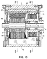
- the stator 14 comprises twelve first cores 11, twelve second cores 12 and twelve third cores 13.
- the first cores 11 are disposed on an outer side of the first rotor 11.
- the second cores 12 are disposed on an outer side of the second rotor 3.
- the third cores 13 are disposed on an outer side of the first cores 11 and the second cores 12.
- the third core 13 of each phase electrically connects the first core 11 and the second core 12.
- the first and second cores 11 and 12 are made of magnetic plate members which are respectively laminated in the direction of the rotating shaft 4.
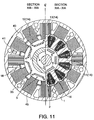
- the third cores 13 are made of magnetic plates laminated in the direction of the periphery of the cylindrical case 1 and are fitted respectively into the slots on the inner periphery of the case which is made of a non-magnetic material. Displacement towards the outer side of the first cores 11 and the second cores 12 is limited by the abutment of the third cores 13 with first cores 11 and second cores 12 of the same phase.
- Indentations 46 are respectively formed on an outer periphery of the first cores 11 and the second cores 12.
- a projection 47 fitting into the indentation 46 is formed on an inner periphery of the third cores 13.
- a wall of the case 1 made of a non-magnetic material is interposed between adjacent third cores 13.
- a magnetic flux is transmitted through the third cores 13 between first cores 11 and second cores 12 of the same phase.
- magnetic resistance between adjacent cores in a circumferential periphery should be much greater than the magnetic resistance passing through the third cores 13 between first cores 11 and second cores 12 of the same phase.
- the retaining plates 18 is made of a non-magnetic material.
- Stator coils 16 are wound on the first cores 11. Coils are not wound on the second cores 12 and the third cores 13.
- the polarity of the inner periphery of the first cores 11 is opposite to the polarity of the inner periphery of the second cores 12 of the same phase. This is due to the fact that the first cores 11 and the second cores 12 are electrically connected through the third cores 13. In contrast, in the second embodiment, the inner periphery of cores 11 and 12 with the same phase has the same polarity.
- a plurality of first water jackets 40, second water jackets 41 and bolt holes 42 are formed approximately parallel to the rotating shaft 4 in the case 1 between the third cores 13.
- the stator coils 16 are heated by variations in the magnetic flux, but the motor/generator is easily cooled by passing a liquid coolant through the water jackets 40 and 41.
- the outer periphery of the third cores 13 is covered with a magnetic shield 45 comprising a thin steel plate or a mesh plate.
- the shield 45 prevents leakage out of the case 1 of high frequency electromagnetic waves resulting from variations in magnetic flux inside the case 1.
- first rotor 2 and the second rotor 3 The structure of the first rotor 2 and the second rotor 3 is the same as that described with reference to the first embodiment. However in this embodiment, ball bearings 44 and 45 are disposed between the rotating shaft 4 and the rotating shaft 5 instead of the needle bearings 30A and 30B in the first embodiment.
- bearings 31 and 32, 44 and 45 create a stable supporting structure for the first rotor 2 and the second rotor 3.
- the structure of the stator 14 is different from that of the fourth embodiment.
- the second cores 12 are replaced by projections formed on the third cores 13.
- the third cores 13 are made of magnetic plates laminated in the direction of the periphery of the cylindrical case 1 In the same manner as the fourth embodiment. Also, the third cores 13 are fitted into the slots of the case 1.
- stator 14 in the same manner as the second embodiment, is provided with twelve first cores 11 disposed on an outer side of the first rotor 2 and twelve second cores 12 which are disposed on an outer side of the second rotor 3.
- Stator coils 16A are wound on the first cores 11.
- Stator coils 16B are wound on the second cores 12.
- the third cores 13 are provided on an outer side of the first cores 11 and the second cores 12 in the same manner as the fourth embodiment.
- the first cores 11 and the second cores 12 of the same phase are electrically connected through the third cores 13.
- the polarity of the inner periphery of the first cores 11 and the inner periphery of second cores 12 of the same phase is opposite.
- the direction of winding of the stator coils 16A and 16B is preset not to interfere with this polarity characteristic.
- the first rotor 2 and the second rotor 3 are disposed along the rotation shaft 5 and the stator 14 is disposed on an outer side of the stators 2, 3.
- the diameter of the motor/generator can be smaller than the motor/generator that disposes the rotors 3 and 4 and the stator 14 to overlap in a radial direction.
- first rotor 2 and the second rotor 3 are disposed co-axially along the rotation shaft 5.
- the first rotor 2 and the second rotor 3 are accommodated in a single case 1 with the stator 14.
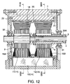
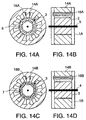
- the rotating shaft 4 of the first rotor 2 and the rotating shaft 5 of the second rotor 3 are not disposed co-axially.
- the first rotor 2 is provided with a six-pole magnet 6 and the second rotor 3 is provided with an eight-pole magnet 7.
- a stator 14A creating a rotating magnetic field for the first rotor 2 and a stator 14B creating a rotating magnetic field for the second rotor 3 are separately provided.
- the stators 14A and 14B are respectively provided with twelve coils 16A and 16B.
- the stator 14A and the first rotor 2 are accommodated in a case 1A.
- the stator 14B and the second rotor 3 are accommodated in a case 1B.
- Coils 16A and 16B of the same phase are connected in series or in parallel to output terminals of an inverter which is formed in the same manner as that described in the first embodiment.
Landscapes
- Engineering & Computer Science (AREA)
- Power Engineering (AREA)
- Permanent Magnet Type Synchronous Machine (AREA)
- Synchronous Machinery (AREA)
Applications Claiming Priority (4)
| Application Number | Priority Date | Filing Date | Title |
|---|---|---|---|
| JP27330399 | 1999-09-27 | ||
| JP27330399A JP3663997B2 (ja) | 1999-09-27 | 1999-09-27 | 複数ロータモータ |
| JP27487499A JP3511955B2 (ja) | 1999-09-28 | 1999-09-28 | 複合モータ |
| JP27487499 | 1999-09-28 |
Publications (3)
| Publication Number | Publication Date |
|---|---|
| EP1087501A2 true EP1087501A2 (fr) | 2001-03-28 |
| EP1087501A3 EP1087501A3 (fr) | 2003-09-03 |
| EP1087501B1 EP1087501B1 (fr) | 2005-11-30 |
Family
ID=26550601
Family Applications (1)
| Application Number | Title | Priority Date | Filing Date |
|---|---|---|---|
| EP00120941A Expired - Lifetime EP1087501B1 (fr) | 1999-09-27 | 2000-09-26 | Moteur/générateur avec plusieurs rotors |
Country Status (3)
| Country | Link |
|---|---|
| US (1) | US6639337B1 (fr) |
| EP (1) | EP1087501B1 (fr) |
| DE (1) | DE60024383T2 (fr) |
Cited By (4)
| Publication number | Priority date | Publication date | Assignee | Title |
|---|---|---|---|---|
| US6611127B2 (en) * | 2000-08-07 | 2003-08-26 | Nissan Motor Co., Ltd. | Drive circuit for motor/generator |
| EP1330020A3 (fr) * | 2002-01-16 | 2005-03-02 | Nissan Motor Company, Limited | Machine électrique tournantes et sa méthode de connection |
| WO2008080575A1 (fr) * | 2006-12-29 | 2008-07-10 | Michael Thoms | Machine synchrone à aimants permanents |
| EP2059996A4 (fr) * | 2006-09-07 | 2012-06-27 | Abb Oy | Systeme de refroidissement d'appareil electrique |
Families Citing this family (31)
| Publication number | Priority date | Publication date | Assignee | Title |
|---|---|---|---|---|
| JP3551164B2 (ja) * | 2001-07-09 | 2004-08-04 | 日産自動車株式会社 | 回転電機の電流検出装置 |
| JP3690355B2 (ja) | 2002-02-12 | 2005-08-31 | 日産自動車株式会社 | 回転電機のステータ支持構造 |
| JP3757890B2 (ja) * | 2002-04-01 | 2006-03-22 | 日産自動車株式会社 | 回転電機の駆動方法 |
| US6958027B2 (en) * | 2002-11-14 | 2005-10-25 | Nissan Motor Co., Ltd. | Hybrid transmission |
| FR2861227B1 (fr) * | 2003-10-21 | 2007-07-13 | Renault Sa | Transmission electrique de puissance mecanique destinee notamment a une transmission de vehicule automobile |
| JP4069859B2 (ja) * | 2003-12-15 | 2008-04-02 | 日産自動車株式会社 | 回転電機の構造 |
| US7230363B2 (en) * | 2004-03-30 | 2007-06-12 | Honeywell International, Inc. | Low profile generator configuration |
| JP2007082283A (ja) * | 2005-09-12 | 2007-03-29 | Denso Corp | 車両用交流発電機 |
| WO2007106134A2 (fr) * | 2006-02-24 | 2007-09-20 | Norman Rittenhouse | Roues de traction commandees electriquement pour vehicules tractes et systeme de suspension pour vehicules tractes |
| JP4620024B2 (ja) * | 2006-03-06 | 2011-01-26 | 本田技研工業株式会社 | 電動機 |
| CN101438482B (zh) * | 2006-03-06 | 2012-01-04 | 本田技研工业株式会社 | 电动机 |
| EP1833147B1 (fr) * | 2006-03-06 | 2010-12-29 | Honda Motor Co., Ltd. | Moteur électrique |
| US7309938B1 (en) * | 2006-05-31 | 2007-12-18 | Smith Kelly S | Rotary power converter |
| FR2915523A1 (fr) * | 2007-04-27 | 2008-10-31 | Snecma Sa | Dispositif de production d'energie electrique dans un moteur a turbine a gaz a double corps |
| US20090167104A1 (en) * | 2008-01-02 | 2009-07-02 | Dunn Randy B | Stackable brushless DC motor |
| US8063501B2 (en) * | 2009-06-10 | 2011-11-22 | Hamilton Sundstrand Corporation | Gas turbine bleed energy recovery via counter rotating generator |
| US8258737B2 (en) * | 2009-06-24 | 2012-09-04 | Casey John R | Electric machine with non-coaxial rotors |
| US20110025157A1 (en) * | 2009-07-28 | 2011-02-03 | Rolls-Royce Corporation | System of electrical generation for counter-rotating open-rotor blade device |
| US8294316B2 (en) * | 2009-07-28 | 2012-10-23 | Rolls-Royce North American Technologies, Inc. | Electrical power generation apparatus for contra-rotating open-rotor aircraft propulsion system |
| GB0920148D0 (en) * | 2009-11-17 | 2009-12-30 | Magnomatics Ltd | Magnetically geared machine for marine generation |
| EP2572440B1 (fr) | 2010-05-17 | 2021-10-20 | Magnomatics Limited | Engrenage magnétique |
| WO2013086558A1 (fr) * | 2011-12-16 | 2013-06-20 | Heron Energy Pte Ltd | Turbine à grande vitesse |
| CN104638856A (zh) * | 2013-11-06 | 2015-05-20 | 久鼎金属实业股份有限公司 | 自行车用的双转子马达 |
| DE102016117911A1 (de) | 2016-09-22 | 2018-03-22 | Volabo Gmbh | Elektrische Maschine |
| US9862289B1 (en) | 2017-02-01 | 2018-01-09 | American Axle & Manufacturing, Inc. | Drive system with limited slip electric differential drive unit |
| EP3665764A4 (fr) * | 2018-10-29 | 2020-10-21 | Ock Kee Baek | Générateur électrique autonome pour la production d'énergie renouvelable, propre, portable et durable |
| WO2020102775A1 (fr) * | 2018-11-16 | 2020-05-22 | The Regents Of The University Of California | Engrenages pour moteur électrique |
| CN109327092B (zh) * | 2018-11-28 | 2020-01-21 | 华中科技大学 | 一种产生两种极对数的永磁电机单绕组设置方法 |
| DE102021101408A1 (de) | 2021-01-22 | 2022-07-28 | Feaam Gmbh | Elektrische maschine, antriebssystem und dessen verwendung |
| DE102021124127A1 (de) | 2021-09-17 | 2023-03-23 | Bayerische Motoren Werke Aktiengesellschaft | Kompakte Antriebsanordnung mit zwei koaxialen elektrischen Antriebsmaschinen |
| CN118783714B (zh) * | 2024-08-20 | 2024-12-31 | 浙江大学 | 一种多轴电机及其拓扑结构设计方法 |
Family Cites Families (26)
| Publication number | Priority date | Publication date | Assignee | Title |
|---|---|---|---|---|
| US3462626A (en) | 1966-12-30 | 1969-08-19 | Hughes Aircraft Co | Torque transferring arrangement |
| US3898490A (en) | 1973-09-24 | 1975-08-05 | Westinghouse Electric Corp | Superconductive AC dynamoelectric machines having two rotors |
| FI60326C (fi) | 1976-03-25 | 1981-12-10 | Eriksson Jarl Thure | Kollekteringsanordning foer oeverfoering av elektrisk stroem mellan minst ett par elektriska ledare vilka kan foersaettas i relativ rotationsroerelse kring en gemensam axel |
| FR2517137B1 (fr) | 1981-11-25 | 1985-11-15 | Cibie Pierre | Machine electrique tournante formant notamment variateur de vitesse ou convertisseur de couple |
| US4503349A (en) | 1983-07-29 | 1985-03-05 | Westinghouse Electric Corp. | Self-excited high current DC electrical pulse generator |
| FR2572229B1 (fr) | 1984-10-22 | 1987-04-17 | Rfb Electromecanismes | Machine tournante a aimants perfectionnee |
| US4644207A (en) * | 1985-04-15 | 1987-02-17 | Rockwell International Corporation | Integrated dual pump system |
| US4785213A (en) * | 1986-05-30 | 1988-11-15 | Satake Engineering Co., Ltd. | Variable speed controlled induction motor |
| JPH0625933B2 (ja) | 1986-10-02 | 1994-04-06 | 科学技術庁航空宇宙技術研究所長 | 複合偏心型回転子による電動直接駆動位置決め装置 |
| DE3740697A1 (de) | 1987-12-01 | 1989-06-22 | Pfaff Ind Masch | Antriebsmotor |
| US5117141A (en) | 1990-07-30 | 1992-05-26 | The United States Of America As Represented By Department Of Energy | Disc rotors with permanent magnets for brushless DC motor |
| JPH06170675A (ja) | 1992-12-04 | 1994-06-21 | Toshiba Mach Co Ltd | 回転電機装置 |
| JP3220535B2 (ja) * | 1992-12-14 | 2001-10-22 | オリエンタルモーター株式会社 | リニアパルスモータ |
| US6005317A (en) | 1993-05-21 | 1999-12-21 | Magna Force, Inc. | Adjustable magnetic coupler |
| JP3052786B2 (ja) | 1995-06-09 | 2000-06-19 | 株式会社デンソー | 車両用駆動装置及びその駆動制御方法 |
| US5668430A (en) * | 1996-04-17 | 1997-09-16 | Dana Corporation | Dual-sectioned switched reluctance motor |
| FR2756118B1 (fr) * | 1996-11-20 | 1999-02-05 | Moteurs Fox | Machine electrique motrice a stockage inertiel alimentee par une source de tension continue autonome |
| US6121705A (en) | 1996-12-31 | 2000-09-19 | Hoong; Fong Chean | Alternating pole AC motor/generator with two inner rotating rotors and an external static stator |
| JPH10257730A (ja) * | 1997-03-07 | 1998-09-25 | Shinko Electric Co Ltd | 同心多軸モータ |
| JP3099769B2 (ja) * | 1997-03-24 | 2000-10-16 | トヨタ自動車株式会社 | 動力出力装置およびその制御方法 |
| AT408045B (de) * | 1998-01-30 | 2001-08-27 | Schroedl Manfred Dipl Ing Dr | Elektrische maschine |
| EP0945963B1 (fr) | 1998-03-25 | 2003-11-05 | Nissan Motor Co., Ltd. | Moteur/générateur |
| JP3480301B2 (ja) | 1998-03-25 | 2003-12-15 | 日産自動車株式会社 | 回転電機 |
| JP3719136B2 (ja) | 2000-01-17 | 2005-11-24 | 日産自動車株式会社 | 回転電機および駆動システム |
| US6304017B1 (en) | 2000-02-18 | 2001-10-16 | The United States Of America As Represented By The Secretary Of The Army | Counter rotating nested cylinders in electrical machinery |
| JP2001298920A (ja) | 2000-04-18 | 2001-10-26 | Tamagawa Seiki Co Ltd | 二軸同芯モータ |
-
2000
- 2000-09-25 US US09/668,348 patent/US6639337B1/en not_active Expired - Fee Related
- 2000-09-26 EP EP00120941A patent/EP1087501B1/fr not_active Expired - Lifetime
- 2000-09-26 DE DE60024383T patent/DE60024383T2/de not_active Expired - Lifetime
Cited By (5)
| Publication number | Priority date | Publication date | Assignee | Title |
|---|---|---|---|---|
| US6611127B2 (en) * | 2000-08-07 | 2003-08-26 | Nissan Motor Co., Ltd. | Drive circuit for motor/generator |
| EP1330020A3 (fr) * | 2002-01-16 | 2005-03-02 | Nissan Motor Company, Limited | Machine électrique tournantes et sa méthode de connection |
| EP2059996A4 (fr) * | 2006-09-07 | 2012-06-27 | Abb Oy | Systeme de refroidissement d'appareil electrique |
| WO2008080575A1 (fr) * | 2006-12-29 | 2008-07-10 | Michael Thoms | Machine synchrone à aimants permanents |
| US7944107B2 (en) | 2006-12-29 | 2011-05-17 | Michael Thoms | Synchronous permanent magnet machine |
Also Published As
| Publication number | Publication date |
|---|---|
| DE60024383T2 (de) | 2006-06-22 |
| DE60024383D1 (de) | 2006-01-05 |
| EP1087501B1 (fr) | 2005-11-30 |
| EP1087501A3 (fr) | 2003-09-03 |
| US6639337B1 (en) | 2003-10-28 |
Similar Documents
| Publication | Publication Date | Title |
|---|---|---|
| US6639337B1 (en) | Motor/generator with multiple rotors | |
| US6798104B2 (en) | Rotary electric machine for electric vehicle | |
| JP6977556B2 (ja) | 回転電機 | |
| US8847464B2 (en) | Electrical machine with improved stator flux pattern across a rotor that permits higher torque density | |
| US20210234415A1 (en) | Rotating electric machine | |
| KR20070119055A (ko) | 모터 | |
| EP0817360B1 (fr) | Moteur pas-à-pas hybride | |
| US20110163641A1 (en) | Permanent-magnet synchronous motor | |
| JP6388611B2 (ja) | ハイブリッド界磁式ダブルギャップ同期機 | |
| US5834866A (en) | Motor structure | |
| US5864197A (en) | Synchronous machine | |
| US6781260B2 (en) | Permanent magnet type rotary machine | |
| JP5301905B2 (ja) | 複数相回転電機駆動装置、複数相発電機用コンバータ、複数相回転電機、及び回転電機駆動システム | |
| WO2024085919A1 (fr) | Moteur à courant continu sans balai à double rotor avec refroidissement par fluide | |
| US7233093B2 (en) | Electric rotating machine | |
| JP3663997B2 (ja) | 複数ロータモータ | |
| US12278523B2 (en) | Electrical machine | |
| JP2018102090A (ja) | ステータおよびモータ | |
| JP2010516224A (ja) | 多相の駆動もしくは発電電気マシン | |
| JP6451990B2 (ja) | 回転電機 | |
| JP3719121B2 (ja) | 回転電機 | |
| US12494683B2 (en) | Surface/interior permanent magnet rotor for an electric machine | |
| US20100194227A1 (en) | Power generator | |
| JP2001119875A (ja) | 同期機及びそれを用いた電気自動車用回転電機 | |
| JP7599584B2 (ja) | 回転子および磁気波動歯車装置 |
Legal Events
| Date | Code | Title | Description |
|---|---|---|---|
| PUAI | Public reference made under article 153(3) epc to a published international application that has entered the european phase |
Free format text: ORIGINAL CODE: 0009012 |
|
| 17P | Request for examination filed |
Effective date: 20000926 |
|
| AK | Designated contracting states |
Kind code of ref document: A2 Designated state(s): AT BE CH CY DE DK ES FI FR GB GR IE IT LI LU MC NL PT SE |
|
| AX | Request for extension of the european patent |
Free format text: AL;LT;LV;MK;RO;SI |
|
| PUAL | Search report despatched |
Free format text: ORIGINAL CODE: 0009013 |
|
| AK | Designated contracting states |
Kind code of ref document: A3 Designated state(s): AT BE CH CY DE DK ES FI FR GB GR IE IT LI LU MC NL PT SE |
|
| AX | Request for extension of the european patent |
Extension state: AL LT LV MK RO SI |
|
| RIC1 | Information provided on ipc code assigned before grant |
Ipc: 7H 02K 17/02 A Ipc: 7H 02P 6/00 B Ipc: 7H 02K 16/00 B Ipc: 7H 02K 16/02 B |
|
| 17Q | First examination report despatched |
Effective date: 20040105 |
|
| AKX | Designation fees paid |
Designated state(s): DE FR GB |
|
| GRAP | Despatch of communication of intention to grant a patent |
Free format text: ORIGINAL CODE: EPIDOSNIGR1 |
|
| GRAS | Grant fee paid |
Free format text: ORIGINAL CODE: EPIDOSNIGR3 |
|
| GRAA | (expected) grant |
Free format text: ORIGINAL CODE: 0009210 |
|
| AK | Designated contracting states |
Kind code of ref document: B1 Designated state(s): DE FR GB |
|
| REG | Reference to a national code |
Ref country code: GB Ref legal event code: FG4D |
|
| REF | Corresponds to: |
Ref document number: 60024383 Country of ref document: DE Date of ref document: 20060105 Kind code of ref document: P |
|
| ET | Fr: translation filed | ||
| PLBE | No opposition filed within time limit |
Free format text: ORIGINAL CODE: 0009261 |
|
| STAA | Information on the status of an ep patent application or granted ep patent |
Free format text: STATUS: NO OPPOSITION FILED WITHIN TIME LIMIT |
|
| 26N | No opposition filed |
Effective date: 20060831 |
|
| PGFP | Annual fee paid to national office [announced via postgrant information from national office to epo] |
Ref country code: GB Payment date: 20090923 Year of fee payment: 10 |
|
| PGFP | Annual fee paid to national office [announced via postgrant information from national office to epo] |
Ref country code: DE Payment date: 20090923 Year of fee payment: 10 |
|
| PGFP | Annual fee paid to national office [announced via postgrant information from national office to epo] |
Ref country code: FR Payment date: 20091012 Year of fee payment: 10 |
|
| GBPC | Gb: european patent ceased through non-payment of renewal fee |
Effective date: 20100926 |
|
| REG | Reference to a national code |
Ref country code: FR Ref legal event code: ST Effective date: 20110531 |
|
| REG | Reference to a national code |
Ref country code: DE Ref legal event code: R119 Ref document number: 60024383 Country of ref document: DE Effective date: 20110401 |
|
| PG25 | Lapsed in a contracting state [announced via postgrant information from national office to epo] |
Ref country code: FR Free format text: LAPSE BECAUSE OF NON-PAYMENT OF DUE FEES Effective date: 20100930 Ref country code: DE Free format text: LAPSE BECAUSE OF NON-PAYMENT OF DUE FEES Effective date: 20110401 |
|
| PG25 | Lapsed in a contracting state [announced via postgrant information from national office to epo] |
Ref country code: GB Free format text: LAPSE BECAUSE OF NON-PAYMENT OF DUE FEES Effective date: 20100926 |