EP1087513A2 - Convertisseur de fréquence pour un moteur électrique - Google Patents
Convertisseur de fréquence pour un moteur électrique Download PDFInfo
- Publication number
- EP1087513A2 EP1087513A2 EP00710018A EP00710018A EP1087513A2 EP 1087513 A2 EP1087513 A2 EP 1087513A2 EP 00710018 A EP00710018 A EP 00710018A EP 00710018 A EP00710018 A EP 00710018A EP 1087513 A2 EP1087513 A2 EP 1087513A2
- Authority
- EP
- European Patent Office
- Prior art keywords
- intermediate circuit
- frequency converter
- voltage
- inverter
- control
- Prior art date
- Legal status (The legal status is an assumption and is not a legal conclusion. Google has not performed a legal analysis and makes no representation as to the accuracy of the status listed.)
- Withdrawn
Links
- 230000001105 regulatory effect Effects 0.000 claims abstract description 9
- 239000004065 semiconductor Substances 0.000 claims description 10
- 229910052710 silicon Inorganic materials 0.000 description 13
- 239000010703 silicon Substances 0.000 description 13
- XUIMIQQOPSSXEZ-UHFFFAOYSA-N Silicon Chemical compound [Si] XUIMIQQOPSSXEZ-UHFFFAOYSA-N 0.000 description 12
- 238000010586 diagram Methods 0.000 description 4
- 238000005516 engineering process Methods 0.000 description 3
- 238000004519 manufacturing process Methods 0.000 description 3
- 230000000712 assembly Effects 0.000 description 2
- 238000000429 assembly Methods 0.000 description 2
- 230000033228 biological regulation Effects 0.000 description 2
- 238000010276 construction Methods 0.000 description 2
- 238000000034 method Methods 0.000 description 2
- 238000004804 winding Methods 0.000 description 2
- 230000009286 beneficial effect Effects 0.000 description 1
- 230000003139 buffering effect Effects 0.000 description 1
- 239000003990 capacitor Substances 0.000 description 1
- 238000009413 insulation Methods 0.000 description 1
- 230000001629 suppression Effects 0.000 description 1
Images


Classifications
-
- H—ELECTRICITY
- H02—GENERATION; CONVERSION OR DISTRIBUTION OF ELECTRIC POWER
- H02P—CONTROL OR REGULATION OF ELECTRIC MOTORS, ELECTRIC GENERATORS OR DYNAMO-ELECTRIC CONVERTERS; CONTROLLING TRANSFORMERS, REACTORS OR CHOKE COILS
- H02P6/00—Arrangements for controlling synchronous motors or other dynamo-electric motors using electronic commutation dependent on the rotor position; Electronic commutators therefor
- H02P6/08—Arrangements for controlling the speed or torque of a single motor
- H02P6/085—Arrangements for controlling the speed or torque of a single motor in a bridge configuration
-
- H—ELECTRICITY
- H02—GENERATION; CONVERSION OR DISTRIBUTION OF ELECTRIC POWER
- H02M—APPARATUS FOR CONVERSION BETWEEN AC AND AC, BETWEEN AC AND DC, OR BETWEEN DC AND DC, AND FOR USE WITH MAINS OR SIMILAR POWER SUPPLY SYSTEMS; CONVERSION OF DC OR AC INPUT POWER INTO SURGE OUTPUT POWER; CONTROL OR REGULATION THEREOF
- H02M7/00—Conversion of AC power input into DC power output; Conversion of DC power input into AC power output
- H02M7/42—Conversion of DC power input into AC power output without possibility of reversal
- H02M7/44—Conversion of DC power input into AC power output without possibility of reversal by static converters
- H02M7/48—Conversion of DC power input into AC power output without possibility of reversal by static converters using discharge tubes with control electrode or semiconductor devices with control electrode
-
- H—ELECTRICITY
- H02—GENERATION; CONVERSION OR DISTRIBUTION OF ELECTRIC POWER
- H02M—APPARATUS FOR CONVERSION BETWEEN AC AND AC, BETWEEN AC AND DC, OR BETWEEN DC AND DC, AND FOR USE WITH MAINS OR SIMILAR POWER SUPPLY SYSTEMS; CONVERSION OF DC OR AC INPUT POWER INTO SURGE OUTPUT POWER; CONTROL OR REGULATION THEREOF
- H02M1/00—Details of apparatus for conversion
- H02M1/0067—Converter structures employing plural converter units, other than for parallel operation of the units on a single load
- H02M1/007—Plural converter units in cascade
Definitions
- PWM frequency converter pulse width modulated frequency converter
- PAM frequency converter pulse amplitude modulated frequency converter
- Frequency inverters of the PAM design essentially consist of a rectifier, in which a single or multi-phase alternating current is rectified, an intermediate circuit (also called a DC intermediate circuit), in which the constant DC voltage of the rectifier by means of an electronic switch is switched on and off, so a variable DC voltage to generate an inverter and a control and regulating circuit.
- an intermediate circuit also called a DC intermediate circuit
- the constant DC voltage applied to the output of the rectifier in particular To be able to increase is a so-called within the DC link Buck Boost Converter provided a Buck Boost Rectifier Diode as well as the aforementioned electronic switch.
- the variable DC voltage generated in the DC link electronic switches connected to the motor windings so that by appropriate Control of the switches a frequency voltage supply of the Motor is achieved, the speed of the motor by selecting the frequency is controlled.
- Two electronic switches are assigned to each motor phase, one of which has the higher potential (high-side) and the other the lower Potential (low-side) switches, so that one for each motor phase Generate AC voltage.
- the control of the switches in the inverter as well the switch in the DC link is made by means of the control and regulation circuit, which at known frequency converters of the PAM design is quite complex.
- the control is so expensive because both the switch of the buck boost converter and usually also at least those sitting on the high side of the inverter N-doped transistors sit in live lines to the motor in such a way that their reference voltage changes constantly according to the motor control. There a control voltage is required to switch these electronic switches, which is above the reference voltage by a defined amount, must be and control circuit for each of these switches the voltage tracked accordingly become what is technically complex.
- the invention has for its object a generic Frequency converter to improve, especially with regard to the Manufacturing costs.
- the basic idea of the present invention is to control the intermediate circuit in such a way that the output voltage of the DC link is always smaller than that Output voltage of the rectifier is.
- the solution according to the invention makes it possible for the inverter to know what is The advantage is on the higher potential side with P-doped semiconductors and on the lower potential side with N-doped semiconductors as electronic switches can be equipped.
- N-doped semiconductors are used because namely the P-doped transistors can only be used up to approx. 150 volts.
- the N-doped Semiconductors used in the state of the art also on the high side not only have the disadvantage that they are significantly more expensive than the P-doped, but they also have that when used on the high side Disadvantage that they are connected to the motor winding so that their reference voltage changes constantly, which also means that the switching required Voltage must be adjusted accordingly.
- the invention enables thus the use of inexpensive P-doped semiconductors on the High side of the inverter, which is also the control of this electronic Switch considerably easier, since no voltage tracking for the Switching voltage is required.
- the switch preferably on the side of the buck boost converter lies on the low side at the output, and the diode on the other Side, i.e. the side that forms the high side at the exit.
- the tax and The control loop can then also be comparatively simple for this switch be constructed.
- the voltage reduction in the DC link also has the advantage that the components in the intermediate circuit and inverter as well as in the control and Control loop instead of the usual 400 volts only a dielectric strength of 50 volts, for example, which makes the use more cost-effective and smaller components.
- passive components can also be used such as capacitors, coils and resistors can be designed more cheaply.
- Another advantage of the frequency converter according to the invention is in particular from the engine manufacturer's point of view, that one and the same unit is attached Networks of different supply voltage and / or frequency can be operated can. Operation on a DC network is also possible, for example enables use in motor vehicles or on boats. So is the invention Frequency converter preferably also modulated in conjunction with a pulse amplitude regulated brushless DC motor for driving a centrifugal pump applicable.
- the use of in this area actually for cost reasons also has unusual buck boost converters in the DC link the advantage of a continuous power output from the frequency converter the engine is running, d. H. that otherwise occur with AC motors There are no interruptions in the power consumption at zero crossing.
- the switch of the buck boost converter can also advantageously be used Suppression of the reactive current or the reactive power can be used what especially in the case of low-power engines in many countries today is prescribed.
- the intermediate circuit 1 shown schematically in FIG. 1 is used by a rectifier 2 applied with a constant DC voltage.
- the input of the DC link 1 is marked with P (positive) and N (negative).
- Within this active DC link 1 becomes the constant DC voltage present at the input changed using a buck boost converter.
- Such an intermediate circuit typically has an electronic switch 3, an inductor 4, a diode 5 and a capacitance 6.
- the capacitance 6 is also used for buffering the voltages generated by the motor.
- Fig. 1 is one DC link, as is known from the prior art, the switch 3 in Row with the diode 5, d. H. on the same side of the DC link.
- Diode 5 on one side of the DC link and switch 3 on the other Side of the DC link Diode 5 on one side of the DC link and switch 3 on the other Side of the DC link.
- the arrangement is preferably as shown in Fig. 2 that namely the diode on the leading the higher potential Side (high-side) and the switch 3 on the leading the lower potential Side (low side) is arranged.
- This has considerable advantages when it comes to control of the switch 3, because then the switching voltage for switching the switch 3 is always constant - namely + 15 volts in the exemplary embodiment according to FIG. 2 -, whereas they always apply to the current voltage in a circuit arrangement according to FIG. 1 track the high side.
- the diode 7 provided in parallel to the switch 3 in FIGS. 1 and 2 is fundamental not necessary, but with the semiconductor components available today at low cost, in particular silicon components, regularly provided.
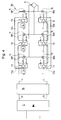
- Fig. 3 The circuit design of a frequency converter according to the state of the Technology is shown with reference to Fig. 3, where the intermediate circuit with 1a, the Rectifier is marked with 2 and the inverter with 8a, accordingly in Fig. 4 each with b the different components / assemblies according to the Execution according to the invention.
- the rectifier 2 supply voltage converted into a DC voltage, which on Input of the intermediate circuit 1a is present, where P is the positive and N the negative Display page.
- the intermediate circuit 1a (for details see Fig. 1) generates a variable DC voltage that the inverter 8a is supplied, the side with the higher potential having H (high side) and the side with the lower potential is marked with L (low side).
- the inverter 8a is used to control a three-phase motor 9 provided, each phase of the motor associated with two electronic switches 10 are, each one for the switching of the higher potential H and one for switching the lower potential L for connection to the respective motor phase is provided.
- the switches 10 are continuously with 10N or 10P, where 10N for N-doped semiconductors, in particular transistor and 10P stands for P-doped semiconductor, in particular transistor.
- Each Switch 10 is connected to a freewheeling diode 11 in parallel.
- the control of this Switch 10 is done exactly like that of switch 3 in the intermediate circuit via the here Control and regulating circuit 12a, not shown in detail, which, depending on the type of construction Silicon components on the one hand and discrete components on the other hand.
- An amplifier 13 is assigned to each switch, the amplifiers possibly also a converter 14 is assigned, as is the case, for example, on the high side of the converter 8a arranged amplifiers and also in the amplifier in Intermediate circuit 1a according to FIG. 1 is provided.
- the frequency converter according to the invention shown in FIG. 4 differs from that The above-described embodiment according to the prior art, first of all in that the intermediate circuit 1b is formed according to FIG. 2, and also in that that P-doped switches 10P are arranged on the high side of the inverter 8b are.
- each switch 10 is an amplifier 13 and on the high side additionally assigned a converter 14, which is also part of a control and regulating circuit 12b and which also includes an amplifier 13 in the intermediate circuit 1b, however, in contrast to the intermediate circuit 1a according to the prior art no converter 14 required there.
- the converters 14, however, are in the embodiment according to the invention as discrete components outside the silicon components 1 5b executed, which is also from Advantage is. If you compare this with a frequency converter according to the state of the 3, it should be noted that these four silicon components 15a required (three for the converter control and one for the DC link control), these silicon modules 15a being comparatively expensive and of a large size since they have different potentials, namely that of the low side and that of the high side in have to process one and the same block, which is expensive in terms of insulation technology is. In contrast, in the invention, each silicon chip has only one and the same Process potential, large potential differences are avoided.
Landscapes
- Engineering & Computer Science (AREA)
- Power Engineering (AREA)
- Inverter Devices (AREA)
- Control Of Ac Motors In General (AREA)
- Dc-Dc Converters (AREA)
Applications Claiming Priority (2)
| Application Number | Priority Date | Filing Date | Title |
|---|---|---|---|
| DE19946242 | 1999-09-27 | ||
| DE19946242A DE19946242A1 (de) | 1999-09-27 | 1999-09-27 | Frequenzumrichter für einen Elektromotor |
Publications (2)
| Publication Number | Publication Date |
|---|---|
| EP1087513A2 true EP1087513A2 (fr) | 2001-03-28 |
| EP1087513A3 EP1087513A3 (fr) | 2004-04-21 |
Family
ID=7923444
Family Applications (1)
| Application Number | Title | Priority Date | Filing Date |
|---|---|---|---|
| EP00710018A Withdrawn EP1087513A3 (fr) | 1999-09-27 | 2000-09-25 | Convertisseur de fréquence pour un moteur électrique |
Country Status (3)
| Country | Link |
|---|---|
| US (1) | US6373728B1 (fr) |
| EP (1) | EP1087513A3 (fr) |
| DE (1) | DE19946242A1 (fr) |
Cited By (1)
| Publication number | Priority date | Publication date | Assignee | Title |
|---|---|---|---|---|
| EP2133991A1 (fr) * | 2008-06-09 | 2009-12-16 | Grundfos Management A/S | Agrégat de pompe centrifuge |
Families Citing this family (21)
| Publication number | Priority date | Publication date | Assignee | Title |
|---|---|---|---|---|
| US8337166B2 (en) | 2001-11-26 | 2012-12-25 | Shurflo, Llc | Pump and pump control circuit apparatus and method |
| US6909622B2 (en) * | 2002-11-05 | 2005-06-21 | Da Feng Weng | Quasi active power factor correction circuit for switching power supply |
| US7026795B2 (en) * | 2003-07-09 | 2006-04-11 | Advanced Analogic Technologies, Inc. | Method for pulse modulation control of switching regulators |
| US8540493B2 (en) | 2003-12-08 | 2013-09-24 | Sta-Rite Industries, Llc | Pump control system and method |
| US8602745B2 (en) | 2004-08-26 | 2013-12-10 | Pentair Water Pool And Spa, Inc. | Anti-entrapment and anti-dead head function |
| US7845913B2 (en) | 2004-08-26 | 2010-12-07 | Pentair Water Pool And Spa, Inc. | Flow control |
| US7686589B2 (en) * | 2004-08-26 | 2010-03-30 | Pentair Water Pool And Spa, Inc. | Pumping system with power optimization |
| US7854597B2 (en) | 2004-08-26 | 2010-12-21 | Pentair Water Pool And Spa, Inc. | Pumping system with two way communication |
| US8019479B2 (en) | 2004-08-26 | 2011-09-13 | Pentair Water Pool And Spa, Inc. | Control algorithm of variable speed pumping system |
| US8469675B2 (en) | 2004-08-26 | 2013-06-25 | Pentair Water Pool And Spa, Inc. | Priming protection |
| US7874808B2 (en) | 2004-08-26 | 2011-01-25 | Pentair Water Pool And Spa, Inc. | Variable speed pumping system and method |
| US8480373B2 (en) | 2004-08-26 | 2013-07-09 | Pentair Water Pool And Spa, Inc. | Filter loading |
| US8217616B2 (en) * | 2007-11-02 | 2012-07-10 | HJamilton Sundstrand Corporation | Electric motor control with buck boost converter |
| EP3418570B1 (fr) | 2008-10-06 | 2020-01-22 | Pentair Water Pool and Spa, Inc. | Procédé d'actionnement d'un système brise-vide de sécurité |
| US9556874B2 (en) | 2009-06-09 | 2017-01-31 | Pentair Flow Technologies, Llc | Method of controlling a pump and motor |
| US8564233B2 (en) | 2009-06-09 | 2013-10-22 | Sta-Rite Industries, Llc | Safety system and method for pump and motor |
| US8436559B2 (en) * | 2009-06-09 | 2013-05-07 | Sta-Rite Industries, Llc | System and method for motor drive control pad and drive terminals |
| BR112013014476A2 (pt) | 2010-12-08 | 2016-09-20 | Pentair Water Pool & Spa Inc | válvula de descarga de alívio de vácuo para um sistema de segurança de liberação de vácuo |
| WO2013067206A1 (fr) | 2011-11-01 | 2013-05-10 | Pentair Water Pool And Spa, Inc. | Système et procédé de blocage de débit |
| US9885360B2 (en) | 2012-10-25 | 2018-02-06 | Pentair Flow Technologies, Llc | Battery backup sump pump systems and methods |
| DE202014103786U1 (de) | 2014-08-14 | 2014-09-29 | Dms Technologie Gmbh | Mobile Arbeitsmaschine und Nachrüstsystem |
Family Cites Families (16)
| Publication number | Priority date | Publication date | Assignee | Title |
|---|---|---|---|---|
| DE2652275A1 (de) * | 1976-11-17 | 1978-05-18 | Boehringer Andreas | Einrichtung ohne prinzipbedingte verluste zur entnahme von praktisch rein sinusfoermigem, netzfrequentem strom aus wechsel- oder drehspannungsnetzen und zur ueberfuehrung der entnommenen elektrischen energie in galvanisch verbundene gleichspannungssysteme oder gleichspannungszwischensysteme |
| CH658348A5 (de) | 1979-11-30 | 1986-10-31 | Papst Motoren Kg | Zweipulsiger kollektorloser gleichstrommotor. |
| GB2167251B (en) * | 1984-11-21 | 1988-10-05 | Barry Wayne Williams | Induction motor drive circuits |
| US4734626A (en) * | 1986-12-23 | 1988-03-29 | Sundstrand Corporation | Double differential, electrically compensated constant speed drive |
| JP2811339B2 (ja) * | 1989-12-20 | 1998-10-15 | 富士通株式会社 | Dc/dcコンバータ |
| JPH0433584A (ja) * | 1990-05-30 | 1992-02-04 | Toshiba Corp | すべり検出装置およびこれを用いた圧縮機の制御装置 |
| US5235504A (en) * | 1991-03-15 | 1993-08-10 | Emerson Electric Co. | High power-factor converter for motor drives and power supplies |
| US5373195A (en) * | 1992-12-23 | 1994-12-13 | General Electric Company | Technique for decoupling the energy storage system voltage from the DC link voltage in AC electric drive systems |
| DE4340604A1 (de) * | 1993-08-25 | 1995-03-02 | Tridonic Bauelemente Ges Mbh | Elektronisches Vorschaltgerät zum Versorgen einer Last, beispielsweise einer Lampe |
| JPH09233827A (ja) * | 1996-02-26 | 1997-09-05 | Matsushita Electric Ind Co Ltd | Pwmインバータ用出力回路 |
| JP3665419B2 (ja) * | 1996-05-02 | 2005-06-29 | 新電元工業株式会社 | 誘導性負荷駆動方法、及びhブリッジ回路制御装置 |
| US5808884A (en) * | 1996-07-16 | 1998-09-15 | Texas Instruments Incorporated | Circuit and method for conserving energy in a boost regulator circuit |
| JPH10191633A (ja) * | 1996-12-25 | 1998-07-21 | Fujitsu Ltd | Ac−dcコンバータ |
| JPH10243652A (ja) * | 1997-02-27 | 1998-09-11 | Fujitsu Ltd | 複合コンバータ回路 |
| US5872703A (en) * | 1997-08-25 | 1999-02-16 | The Charles Machine Works, Inc. | System and method for regulating power in tank circuits having a bridge configuration |
| US6121800A (en) * | 1998-07-07 | 2000-09-19 | Lucent Technologies, Inc. | Impedance matched, voltage-mode H-bridge write drivers |
-
1999
- 1999-09-27 DE DE19946242A patent/DE19946242A1/de not_active Ceased
-
2000
- 2000-09-25 EP EP00710018A patent/EP1087513A3/fr not_active Withdrawn
- 2000-09-27 US US09/671,218 patent/US6373728B1/en not_active Expired - Fee Related
Cited By (4)
| Publication number | Priority date | Publication date | Assignee | Title |
|---|---|---|---|---|
| EP2133991A1 (fr) * | 2008-06-09 | 2009-12-16 | Grundfos Management A/S | Agrégat de pompe centrifuge |
| WO2009149796A3 (fr) * | 2008-06-09 | 2010-03-18 | Grundfos Management A/S | Ensemble pompe centrifuge |
| US8690549B2 (en) | 2008-06-09 | 2014-04-08 | Grundfos Management A/S | Centrifugal pump unit |
| CN102057566B (zh) * | 2008-06-09 | 2014-06-11 | 格伦德福斯管理联合股份公司 | 离心泵组 |
Also Published As
| Publication number | Publication date |
|---|---|
| DE19946242A1 (de) | 2001-04-05 |
| EP1087513A3 (fr) | 2004-04-21 |
| US6373728B1 (en) | 2002-04-16 |
Similar Documents
| Publication | Publication Date | Title |
|---|---|---|
| DE19946242A1 (de) | Frequenzumrichter für einen Elektromotor | |
| EP1145416B1 (fr) | Convertisseurs pour la transformation d'energie electrique | |
| DE69302461T2 (de) | Spannungssteuerschaltungen | |
| DE102008032876B4 (de) | Verfahren, Schaltungsanordnung und Brückenschaltung | |
| DE10214190B4 (de) | Stromversorgung mit mehreren parallel geschalteten Schaltnetzteilen | |
| EP2515424B1 (fr) | Convertisseur de tension continue | |
| DE19724356C2 (de) | Energieversorgungsschaltung für ein Kraftfahrzeugbordnetz mit drei Spannungsebenen | |
| DE1763820A1 (de) | Gleichspannungs-Gleichspannungs-Wandler | |
| EP1157320B1 (fr) | Procede permettant de generer une tension continue regulee a partir d'une tension alternative, et dispositif d'alimentation en courant pour la mise en oeuvre de ce procede | |
| EP0802617A2 (fr) | Circuit électronique de puissance | |
| CH698835B1 (de) | Eigenstromversorgung für Stromrichterschaltertreiber. | |
| EP1303032A2 (fr) | Dispositif de commande pour un convertisseur résonnant | |
| DE112016004961T5 (de) | Mehrphasenwandler | |
| DE102011011330A1 (de) | Tiefsetzsteller | |
| DE112022003728T5 (de) | Spannungsregler und Stromumwandlungsvorrichtung | |
| DE10059331A1 (de) | Verringerung von Systemeigenschwingungen bei einem an einem Umrichter mit Spannungszwischenkreis betriebenen elektrischen Motor durch periodisches Abkoppeln des Zwischenkreises vom Netz sowie korrespondierender Spannungszwischenkreis-Umrichter | |
| DE69206503T2 (de) | Hochgeschwindigkeits-gleichstrommotor. | |
| DE60109473T2 (de) | Resonanzumsetzer | |
| WO2016012465A1 (fr) | Circuit pour onduleur multipoints npc comprenant un réseau de décharge | |
| DE102004035248B4 (de) | Resonanzwandler | |
| DE102007040166B4 (de) | Motorsteuerungsvorrichtung | |
| DE19851831B4 (de) | Mehrphasen-Stromrichter | |
| WO2013064318A2 (fr) | Convertisseur de tension comportant un premier circuit parallèle | |
| DE102021104567A1 (de) | Umrichter sowie Verfahren zum Betrieb eines Umrichters | |
| EP1081841A2 (fr) | Arrangement de circuit pour un redresseur |
Legal Events
| Date | Code | Title | Description |
|---|---|---|---|
| PUAI | Public reference made under article 153(3) epc to a published international application that has entered the european phase |
Free format text: ORIGINAL CODE: 0009012 |
|
| AK | Designated contracting states |
Kind code of ref document: A2 Designated state(s): AT BE CH CY DE DK ES FI FR GB GR IE IT LI LU MC NL PT SE |
|
| AX | Request for extension of the european patent |
Free format text: AL;LT;LV;MK;RO;SI |
|
| PUAL | Search report despatched |
Free format text: ORIGINAL CODE: 0009013 |
|
| AK | Designated contracting states |
Kind code of ref document: A3 Designated state(s): AT BE CH CY DE DK ES FI FR GB GR IE IT LI LU MC NL PT SE |
|
| AX | Request for extension of the european patent |
Extension state: AL LT LV MK RO SI |
|
| 17P | Request for examination filed |
Effective date: 20040929 |
|
| AKX | Designation fees paid |
Designated state(s): AT BE CH CY DE DK ES FI FR GB GR IE IT LI LU MC NL PT SE |
|
| 17Q | First examination report despatched |
Effective date: 20090423 |
|
| STAA | Information on the status of an ep patent application or granted ep patent |
Free format text: STATUS: THE APPLICATION IS DEEMED TO BE WITHDRAWN |
|
| 18D | Application deemed to be withdrawn |
Effective date: 20101228 |