EP1087560B1 - System und vorrichtung zur multiplexübertragung in einem cdma system - Google Patents
System und vorrichtung zur multiplexübertragung in einem cdma system Download PDFInfo
- Publication number
- EP1087560B1 EP1087560B1 EP99912124A EP99912124A EP1087560B1 EP 1087560 B1 EP1087560 B1 EP 1087560B1 EP 99912124 A EP99912124 A EP 99912124A EP 99912124 A EP99912124 A EP 99912124A EP 1087560 B1 EP1087560 B1 EP 1087560B1
- Authority
- EP
- European Patent Office
- Prior art keywords
- base band
- band signal
- signal
- correcting
- comparing
- Prior art date
- Legal status (The legal status is an assumption and is not a legal conclusion. Google has not performed a legal analysis and makes no representation as to the accuracy of the status listed.)
- Expired - Lifetime
Links
Images


Classifications
-
- H—ELECTRICITY
- H04—ELECTRIC COMMUNICATION TECHNIQUE
- H04L—TRANSMISSION OF DIGITAL INFORMATION, e.g. TELEGRAPHIC COMMUNICATION
- H04L27/00—Modulated-carrier systems
- H04L27/32—Carrier systems characterised by combinations of two or more of the types covered by groups H04L27/02, H04L27/10, H04L27/18 or H04L27/26
- H04L27/34—Amplitude- and phase-modulated carrier systems, e.g. quadrature-amplitude modulated carrier systems
- H04L27/36—Modulator circuits; Transmitter circuits
- H04L27/366—Arrangements for compensating undesirable properties of the transmission path between the modulator and the demodulator
- H04L27/367—Arrangements for compensating undesirable properties of the transmission path between the modulator and the demodulator using predistortion
- H04L27/368—Arrangements for compensating undesirable properties of the transmission path between the modulator and the demodulator using predistortion adaptive predistortion
-
- H—ELECTRICITY
- H04—ELECTRIC COMMUNICATION TECHNIQUE
- H04B—TRANSMISSION
- H04B7/00—Radio transmission systems, i.e. using radiation field
- H04B7/24—Radio transmission systems, i.e. using radiation field for communication between two or more posts
- H04B7/26—Radio transmission systems, i.e. using radiation field for communication between two or more posts at least one of which is mobile
- H04B7/2628—Radio transmission systems, i.e. using radiation field for communication between two or more posts at least one of which is mobile using code-division multiple access [CDMA] or spread spectrum multiple access [SSMA]
-
- H—ELECTRICITY
- H04—ELECTRIC COMMUNICATION TECHNIQUE
- H04W—WIRELESS COMMUNICATION NETWORKS
- H04W52/00—Power management, e.g. Transmission Power Control [TPC] or power classes
- H04W52/04—Transmission power control [TPC]
Definitions
- the present invention relates to a CDMA (code division multiple access) type multiple transmission apparatus and a CDMA type multiple transmission method in which an electric power of a transmission signal is controlled when pieces of transmission data of a plurality of channels are multiplexed with each other and are transmitted as the transmission signal.
- CDMA code division multiple access
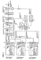
- Fig. 1 is a constitutional diagram of a conventional CDMA type multiple transmission apparatus.
- 1 indicates a channel section in which transmission data of a channel CH1 is multiplied by a spread code
- 2 indicates a channel section in which transmission data of a channel CH2 is multiplied by a spread code
- 4 indicates a spread code generating unit for generating the spread code peculiar to the corresponding channel
- 5 indicates a mixer for multiplying the transmission data by the corresponding spread code.
- Each of 6 to 8 indicates an electric power control unit for controlling an amplitude of the corresponding transmission data spread-modulated in the corresponding channel section 1, 2 or 3 and setting an electric power of the corresponding transmission data
- 9 indicates a multiplexing unit for adding the pieces of transmission data output from the electric power control units 6 to 8 to each other to multiplex the pieces of transmission data with each other and outputting a base band signal (an isophase (I) component and a quadrature (Q) component)
- 10 indicates a digital-to-analog (D/A) converting unit for converting a digital signal, which indicates the base band signal output from the multiplexing unit 9, to an analog signal indicating the base band signal
- 11 indicates a carrier wave generating unit for generating a carrier wave
- 12 indicates an orthogonal modulating unit for orthogonally modulating the base band signal, which is converted to the analog signal in the D/A converting unit 10, with the carrier wave generated in the carrier wave generating unit 11 and outputting a transmission signal.
- 13 indicates a variable attenuator for correcting the electric power of the transmission signal output from the orthogonal modulating unit 12 according to a correction signal output from a D/A converting unit 21
- 14 indicates a radio transmitter for modulating the transmission signal, of which the electric power is corrected in the variable attenuator 13, to a transmission signal of a radio frequency band
- 15 indicates a distributor for distributing the transmission signal output from the radio transmitter 14
- 16 indicates an antenna for radiating the transmission signal distributed in the distributor 15.
- 17 indicates a diode for detecting the electric power of the transmission signal distributed in the distributor 15 and outputting a detection signal indicating the electric power of the transmission signal
- 18 indicates an analog-to-digital (A/D) converting unit for converting an analog signal indicating the detection signal to a digital signal indicating the detection signal
- 19 indicates a data storing unit for storing an electric power table indicating the relationship between a summed value of the electric powers of the pieces of transmission data output from the electric power control units 6 to 8 and the electric power of the transmission signal to be output from the radio transmitter
- 20 indicates an electric power correcting unit for measuring values of the electric powers of the pieces of transmission data output from the electric power control units 6 to 8 and outputting the correction signal according to the measured result and the detection signal
- 21 indicates the D/A converting unit for converting a digital signal, which indicates the correction signal output from the electric power correcting unit 20 to an analog signal indicating the correction signal.
- the transmission data of a corresponding channel is multiplied by a spread code peculiar to the corresponding channel, and the pieces of transmission data of the channels CH1 to CH-N are respectively spread-modulated.
- amplitudes of the pieces of transmission data of the channels CH1 to CH-N are respectively controlled in the electric power control units 6 to 8 to set electric powers of the pieces of transmission data of the channels CH1 to CH-N to prescribed electric power values set in advance.
- the pieces of transmission data of the channels CH1 to CH-N output from the electric power control units 6 to 8 are added to each other in the multiplexing unit 9 to be multiplexed with each other, and a base band signal composed of an I component and a Q component is output.
- the analog base band signal is orthogonally modulated in the orthogonal modulating unit 12 by using a carrier wave generated in the carrier wave generating unit 11, and a transmission signal is output.
- the electric power of the transmission signal is corrected in the variable attenuator 13 according to a correction signal output from the D/A converting unit 21.
- the electric powers of the pieces of transmission data are set in the electric power control units 6 to 8, because there is a case where an electric power of the transmission signal radiated from the antenna 16 deviates from a desired value for electric power (in cases where the electric power of the transmission signal deviates from a desired value for electric power, a channel corresponding to the transmission data of a high electric power may interfere with a channel corresponding to the transmission data of a low electric power), the electric power of the transmission signal is corrected in the variable attenuator 13 according to the correction signal.
- the electric power of the transmission signal is corrected to heighten the electric power of the transmission signal.
- the electric power of the transmission signal is corrected to lower the electric power of the transmission signal.
- the transmission signal is modulated to a transmission signal of a radio frequency band in the radio transmitter 14, and the transmission signal is radio-transmitted through the antenna 16.
- the transmission signal is radio-transmitted.
- the electric power of the transmission signal deviates from a desired value for electric power
- the electric power of the transmission signal distributed in the distributor 15 is detected in the diode 17, and a detection signal indicating the electric power of the transmission signal is output.
- the electric powers of the pieces of transmission data are measured in the electric power correcting unit 20.
- the electric power of each piece of transmission data is, for example, measured by substituting an I component and a Q component of the transmission data into a following equation for I and Q and converting the I component and the Q component to values equivalent to the electric powers of the I and Q components.
- electric power of transmission data I 2 + Q 23 1 / 2
- the electric power correcting unit 20 searches the electric power table stored in the data storing unit 19 for an electric power value (a desired electric power value) of the transmission signal corresponding to a summed value of the electric powers of the pieces of transmission data.
- the desired electric power value is compared in the electric power correcting unit 20 with the electric power value (that is, an analog detection signal output from the A/D converting unit 18) of the transmission signal transmitted from the antenna 16.
- the electric power value that is, an analog detection signal output from the A/D converting unit 18
- the electric power of the transmission signal does not deviate from a desired value for electric power.
- a correction signal depending on the difference between the electric power of the transmission signal and the desired electric power value is produced in the electric power correcting unit 20.
- a correction signal is produced which indicates the heightening of the electric power of the transmission signal.
- a correction signal is produced which indicates the lowering of the electric power of the transmission signal.
- a digital signal which indicates the correction signal produced in the electric power correcting unit 20, is converted to an analog signal in the D/A converting unit 21, and the analog correction signal is transmitted to the variable attenuator 13.
- the electric power of the transmission signal transmitted from the antenna 16 can agree with the desired electric power value on condition that the electric powers of the pieces of transmission data output from the electric power control units 6 to 8 and the electric power of the transmission signal are correctly measured.
- a difference between an average value of the electric power and an effective value of the electric power becomes large because of the influence of a peak factor of the electric power.
- the present invention is provided to solve the above problems, and an object of the present invention is to provide a CDMA type multiple transmission apparatus and a CDMA type multiple transmission method in which an electric power of a transmission signal is precisely corrected without storing an electrical power table fitted to an electric power ratio of pieces of transmission data.
- JP 10-041919 that relates to attaining reception always stably from all channels by inserting a power measurement power control code to a spread code of each channel and measuring transmission power of each channel in an output of a radio section so as to control the transmission power of each channel to be arranged as a prescribed value.
- a power control section uses transmission data spread and outputted from a channel section as a 1st input and uses a power control signal outputted from an inverse spread section as a 2nd input to select and correct amplitude data and provide an output.
- a frequency conversion section receiving a power control output converts the signal into a prescribed frequency band and provides an output.
- the inverse spread section uses the frequency-converted signal as a 1 st input and uses the power control code generated by a power control code generating section as a 2nd input to conduct inverse spread processing thereby detecting an instantaneous power of each channel.
- the inverse spread processing is conducted in the order of channels according to a clock received from a timing control section and a power control signal is outputted to each power control section.
- the present invention provides a CDMA type multiple transmission apparatus in accordance with independent claim 1 as well as a CDMA type multiple transmission method in accordance with independent claim 6. Preferred embodiments of the invention are reflected in the dependent claims.
- a CDMA type multiple transmission apparatus comprises a correcting means for comparing a base band signal output by a multiplexing means with a demodulated base band signal output by a receiving means and correcting the base band signal output by the multiplexing means according to a compared result. Therefore, an electric power of a transmission signal can be precisely corrected without storing an electric power table fitted to an electric power ratio of pieces of transmission data.
- the correcting means comprises a D/A converting unit for converting a digital signal, which indicates the base band signal output by the multiplexing means, to an analog signal indicating the base band signal; a comparing unit for comparing the base band signal output by the D/A converting unit with the demodulated base band signal output by the receiving means; and a vector adjusting unit for correcting the base band signal output from the D/A converting unit according to an error signal, which indicates a compared result of the comparing unit, and outputting the corrected base band signal to the transmitting means.
- the correcting means comprises an A/D converting unit for converting an analog signal, which indicates the demodulated base band signal output from the receiving means, to a digital signal indicating the demodulated base band signal; a comparing and correcting unit for comparing the base band signal output by the multiplexing means with the demodulated base band signal output from the A/D converting unit and correcting the base band signal output by the multiplexing means according to a compared result; and a D/A converting unit for converting a digital signal, which indicates the base band signal corrected in the comparing and correcting unit, to an analog signal, which indicates the base band signal corrected in the comparing and correcting unit, and outputting the analog signal to the transmitting means.
- the configuration of the apparatus is not complicated, and the electric power of the transmission signal can be corrected.
- an amplitude of an I component and an amplitude of a Q component in the base band signal are corrected by the correcting means.
- a phase of an I component and a phase of a Q component in the base band signal are corrected by the correcting means.
- a CDMA type multiple transmission method comprises the steps of comparing a base band signal, which is obtained by multiplexing pieces of transmission data spread-modulated with each other, with a demodulated base band signal orthogonally demodulated; and correcting the base band signal, which is obtained by multiplexing the pieces of transmission data spread-modulated with each other, according to a compared result of the comparing step.
- an electric power of a transmission signal can be precisely corrected without storing an electric power table fitted to an electric power ratio of pieces of transmission data.
- the step of comparing the base band signal comprises the steps of converting a digital signal indicating the base band signal, which is obtained by multiplexing the pieces of transmission data spread-modulated with each other, to an analog signal indicating the base band signal; and comparing the analog signal indicating the base band signal with the demodulated base band signal orthogonally demodulated, and the step of correcting the base band signal includes the step of correcting the analog signal indicating the base band signal according to an error signal, which indicates the compared result of the comparing step.
- the step of comparing the base band signal comprises the steps of converting an analog signal, which indicates the demodulated base band signal orthogonally demodulated, to a digital signal indicating the demodulated base band signal; and comparing the base band signal, which is obtained by multiplexing the pieces of transmission data spread-modulated with each other, with the digital signal indicating the demodulated base band signal, and the step of correcting the base band signal comprises the steps of correcting the base band signal, which is obtained by multiplexing the pieces of transmission data spread-modulated with each other, according to the compared result of the comparing step; and converting a digital signal, which indicates the base band signal corrected in the correcting step, to an analog signal which indicates the base band signal corrected in the correcting step.
- the step of correcting the base band signal includes the step of correcting an amplitude of an I component and an amplitude of a Q component in the base band signal.
- the step of correcting the base band signal includes the step of correcting a phase of an I component and a phase of a Q component in the base band signal.
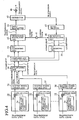
- Fig. 2 is a constitutional diagram of a CDMA type multiple transmission apparatus according to a first embodiment of the present invention.
- 31 indicates a channel section (spread modulating means) in which transmission data of a channel CH1 is multiplied by a spread code
- 32 indicates a channel section (spread modulating means) in which transmission data of a channel CH2 is multiplied by a spread code
- 34 indicates a spread code generating unit for generating the spread code peculiar to the corresponding channel
- 35 indicates a mixer for multiplying the transmission data by the corresponding spread code.
- Each of 36 to 38 indicates an electric power control unit for controlling an amplitude of the corresponding transmission data spread-modulated in the corresponding channel section 31, 32 or 33 and setting an electric power of the corresponding transmission data
- 39 indicates a multiplexing unit for adding the pieces of transmission data output from the electric power control units 36 to 38 to each other to multiplex the pieces of transmission data with each other and outputting a base band signal (an I component and a Q component)
- 40 indicates a digital -to-analog (D/A) converting unit (correcting means) for converting a digital signal, which indicates the base band signal output from the multiplexing unit 39, to an analog signal indicating the base band signal
- 41 indicates a carrier wave generating unit for generating a carrier wave
- 42 indicates a vector adjusting unit (correcting means) for correcting the base band signal output from the D/A converting unit 40 according to error signals output from a comparing unit 49
- 43 indicates an orthogonal modulating unit for orthogonally modulating the base band signal, which is corrected
- 47 indicates a radio receiver (receiving means) for receiving the transmission signal distributed in the distributor 45
- 48 indicates an orthogonal demodulating unit (receiving means) for orthogonally demodulating the transmission signal received in the radio receiver 47 and outputting a demodulated base band signal
- 49 indicates the comparing unit (correcting means) for comparing the base band signal output from the D/A converting unit 40 with the demodulated base band signal output from the orthogonal demodulating unit 48 and outputting the error signals indicating a compared result.
- Fig. 3 is a flow chart showing the CDMA type multiple transmission method according to the first embodiment of the present invention.
- the transmission data of a corresponding channel is multiplied by a spread code peculiar to the corresponding channel, and the pieces of transmission data of the channels CH1 to CH-N are respectively spread-modulated (step ST1).
- amplitudes of the pieces of transmission data of the channels CH1 to CH-N are respectively controlled in the electric power control units 36 to 38 to set electric powers of the pieces of transmission data of the channels CH1 to CH-N to prescribed electric power values set in advance(step ST2).
- the pieces of transmission data of the channels CH1 to CH-N output from the electric power control units 36 to 38 are added to each other in the multiplexing unit 39 to be multiplexed with each other, and a base band signal composed of an I component and a Q component is output (step ST3).
- step ST4 After a digital signal indicating the base band signal is converted to an analog signal in the D/A converting unit 40, the analog base band signal output from the D/A converting unit 40 is corrected in the vector adjusting unit 42 according to error signals output from the comparing unit 49 (step ST4).
- the base band signal is corrected in the vector adjusting unit 42 according to the error signals (the I component of the base band signal is corrected according to the error signal of the I component, and the Q component of the base band signal is corrected according to the error signal of the Q component).
- the base band signal is corrected to heighten the amplitude of the I component (or the Q component) of the base band signal.
- the base band signal is corrected to lower the amplitude of the I component (or the Q component) of the base band signal.
- the base band signal is corrected in the vector adjusting unit 42, the base band signal is orthogonally modulated in the orthogonal modulating unit 43 by using a carrier wave generated in the carrier wave generating unit 41, and a transmission signal is output (step ST5).
- the transmission signal is output from the orthogonal modulating unit 43, the transmission signal is modulated to a transmission signal of a radio frequency band in the radio transmitter 44, and the transmission signal is radio-transmitted through the antenna 46 (step ST6).
- the transmission signal is radio-transmitted.
- the transmission signal distributed in the distributor 45 is received in the radio receiver 47, the transmission signal is orthogonally demodulated in the orthogonal demodulating unit 48, and a demodulated base band signal is output from the orthogonal demodulating unit 48.
- the I component of the base band signal output from the D/A converting unit 40 is compared in the comparing unit 49 with the I component of the demodulated base band signal output from the orthogonal demodulating unit 48, and the error signal of the I component is output.
- the Q component of the base band signal output from the D/A converting unit 40 is compared in the comparing unit 49 with the Q component of the demodulated base band signal output from the orthogonal demodulating unit 48, and the error signal of the Q component is output.
- error signals are output which indicate the heightening of the electric power of the transmission signal.
- the error signals are output which indicate the lowering of the electric power of the transmission signal.
- the error signals output from the comparing unit 49 are transmitted to the vector adjusting unit 42, and both the I component and the Q component of the base band signal to be output to the orthogonal modulating unit 43 are corrected according to the error signals as is described above.
- the base band signal output from the D/A converting unit 40 is compared with the demodulated base band signal output from the orthogonal demodulating unit 48, and the base band signal output from the D/A converting unit 40 is corrected according to the compared result. Accordingly, the electric power of the transmission signal can be precisely corrected without storing an electric power table fitted to an electric power ratio of the pieces of transmission data.
- Fig. 4 is a constitutional diagram of a CDMA type multiple transmission apparatus according to a second embodiment of the present invention.
- constituent elements which are indicated by the same reference numerals as those indicating the constituent elements of Fig. 2 , are the same as those of Fig. 2 , so that the description of the same constituent elements as those of Fig. 2 is omitted.
- 51 indicates an A/D converting unit (correcting means) for converting an analog signal, which indicates the demodulated base band signal output from the orthogonal demodulating unit 48, to a digital signal indicating the demodulated base band signal
- 52 indicates a comparing and correcting unit (correcting means) for comparing the base band signal output from the multiplexing unit 39 with the demodulated base band signal output from the A/D converting unit 51 and correcting the base band signal output from the multiplexing unit 39 according to a compared result
- 53 indicates a D/A converting unit (correcting means) for converting a digital signal, which indicates the base band signal corrected in the comparing and correcting unit 52, to an analog signal indicating the base band signal.
- the analog base band signal output from the D/A converting unit 40 is compared in the comparing unit 49 with the analog demodulated base band signal output from the orthogonal demodulating unit 48, and the analog base band signal output from the D/A converting unit 40 is corrected in the vector adjusting unit 42.
- the digital base band signal output from the multiplexing unit 39 is compared in the comparing and correcting unit 52 with the digital demodulated base band signal output from the A/D converting unit 51, and the digital base band signal output from the multiplexing unit 39 is corrected according to a compared result in the comparing and correcting unit 52. Therefore, the same effect as that obtained in the first embodiment can be obtained.
- the amplitudes of both the I component and the Q component of the base band signal are corrected according to the compared result in the vector adjusting unit 42 or the comparing and correcting unit 52.
- phases of both the I component and the Q component of the base band signal be corrected according to the compared result in the vector adjusting unit 42 or the comparing and correcting unit 52. Therefore, the same effect as that obtained in the first and second embodiments can be obtained.
- the CDMA type multiple transmission apparatus and the CDMA type multiple transmission method according to the present invention are suitable to prevent the interference between channels by controlling a transmission electric power of a transmission signal in cases where pieces of transmission data of a plurality of channels are multiplexed with each other and are transmitted as the transmission signal.
Landscapes
- Engineering & Computer Science (AREA)
- Computer Networks & Wireless Communication (AREA)
- Signal Processing (AREA)
- Mobile Radio Communication Systems (AREA)
- Transmitters (AREA)
Claims (10)
- Mehrfachübertragungsvorrichtung vom CDMA-Typ, die Folgendes aufweist:Spreizmodulationseinrichtungen (31-33) zum Spreizmodulieren von Übertragungsdaten einer Vielzahl von Kanälen durch Multiplikation der Übertragungsdaten jedes Kanals mit einem Spreizcode;eine Multiplexiereinrichtung (39) zum Multiplexieren der Übertragungsdaten, die von den Spreizmodulationseinrichtungen spreizmoduliert werden, miteinander und zum Ausgeben eines Basisbandsignals;Sendeeinrichtungen (43, 44) zum orthogonalen Modulieren des von der Multiplexiereinrichtung ausgegebenen Basisbandsignals und zum Modulieren des orthogonal modulierten Basisbandsignals, um ein HF-Band-Übertragungssignal auszugeben;Empfangseinrichtungen (47, 48) zum Empfangen des von den Sendeeinrichtungen ausgegebenen HF-Band-Übertragungssignals, zum orthogonalen Demodulieren des empfangenen Übertragungssignals und zum Ausgeben eines demodulierten Basisbandsignals; undKorrektureinrichtungen (40, 42, 49; 51-53) zum Vergleichen des von der Multiplexiereinrichtung ausgegebenen Basisbandsignals mit dem von den Empfangseinrichtungen ausgegebenen demodulierten Basisbandsignals und zum Korrigieren des von der Multiplexiereinrichtung ausgegebenen Basisbandsignals entsprechend einem Vergleichsergebnis.
- Mehrfachübertragungsvorrichtung vom CDMA-Typ nach Anspruch 1, wobei die Korrektureinrichtungen Folgendes aufweisen:eine D/A-Umwandlungseinheit (40) zum Umwandeln eines Digitalsignals, welches das von der Multiplexiereinrichtung ausgegebene Basisbandsignal bezeichnet, in ein Analogsignal, welches das Basisbandsignal bezeichnet;eine Vergleichseinheit (49) zum Vergleichen des von der D/A-Umwandlungseinheit ausgegebenen Basisbandsignals mit dem von den Empfangseinrichtungen ausgegebenen demodulierten Basisbandsignal; undeine Vektoreinstelleinheit (42) zum Korrigieren des von der D/A-Umwandlungseinheit ausgegebenen Basisbandsignals entsprechend einem Fehlersignal, das ein Vergleichsergebnis der Vergleichseinheit bezeichnet, und zum Ausgeben des korrigierten Basisbandsignals an die Sendeeinrichtungen.
- Mehrfachübertragungsvorrichtung vom CDMA-Typ nach Anspruch 1, wobei die Korrektureinrichtungen Folgendes aufweisen:eine A/D-Umwandlungseinheit (51) zum Umwandeln eines Analogsignals, welches das von den Empfangseinrichtungen ausgegebene demodulierte Basisbandsignal bezeichnet, in ein Digitalsignal, welches das demodulierte Basisbandsignal bezeichnet;eine Vergleichs- und Korrektureinheit (52) zum Vergleichen des von der Multiplexiereinrichtung ausgegebenen Basisbandsignals mit dem von der A/D-Umwandlungseinheit ausgegebenen demodulierten Basisbandsignal und zum Korrigieren des von der Multiplexiereinrichtung ausgegebenen Basisbandsignals entsprechend einem Vergleichsergebnis; undeine D/A-Umwandlungseinheit (53) zum Umwandeln eines Digitalsignals, welches das in der Vergleichs- und Korrektureinheit korrigierte Basisbandsignal bezeichnet, in ein Analogsignal, welches das in der Vergleichs- und Korrektureinheit korrigierte Basisbandsignal bezeichnet, und zum Ausgeben des Analogsignals an die Sendeeinrichtungen.
- Mehrfachübertragungsvorrichtung vom CDMA-Typ Anspruch 1, wobei eine Amplitude einer I-Komponente und eine Amplitude einer Q-Komponente in dem Basisbandsignal von den Korrektureinrichtungen korrigiert werden.
- Mehrfachübertragungsvorrichtung vom CDMA-Typ nach Ansspruch 1, wobei eine Phase einer I-Komponente und eine Phase einer Q-Komponente in dem Basisbandsignal von den Korrektureinrichtungen korrigiert werden.
- Mehrfachübertragungsverfahren vom CDMA-Typ, das die folgenden Schritte aufweist:Spreizmodulieren von Übertragungsdaten einer Vielzahl von Kanälen durch Mulitplikation der Übertragungsdaten jedes Kanals mit einem Spreizcode;Multiplexieren der spreizmodulierten Übertragungsdaten miteinander, um ein Basisbandsignal auszugeben;orthogonales Modulieren des Basisbandsignals;Modulieren des orthogonal modulierten Basisbandsignals, um ein HF-Band-Übertragungssignal auszugeben;Empfangen des HF-Band-Übertragungssignals;orthogonales Demodulieren des empfangenen Übertragungssignals, um ein demoduliertes Basisbandsignal auszugeben;Vergleichen des Basisbandsignals, das durch Multiplexieren der spreizmodulierten Übertragungsdaten miteinander erhalten wird, mit dem demodulierten Basisbandsignal, welches orthogonal demoduliert wird, undKorrigieren des Basisbandsignals, das duch Multiplexieren der spreizmodulierten Übertragungsdaten miteinander erhalten wird, entsprechend einem Vergleichsergebnis des Vergleichsschritts.
- Mehrfachübertragungsverfahren vom CDMA-Typ nach Anspruch 6, wobei der Schritt des Vergleichens des Basisbandsignals die folgenden Schritte aufweist:Umwandeln eines Digitalsignals, welches das Basisbandsignal bezeichnet, das durch Multiplexieren der spreizmodulierten Übertragungsdaten miteinander erhalten wird, in ein Analogsignal, welches das Basisbandsignal bezeichnet; undVergleichen des Analogsignals, welches das Basisbandsignal bezeichnet, mit dem demodulierten Basisbandsignal, welches orthogonal demoduliert ist, und wobei der Schritt des Korrigierens des Basisbandsignals den folgenden Schritt aufweist:Korrigieren des Analogsignals, welches das Basisbandsignal bezeichnet, entsprechend einem Fehlersignal, welches das Vergleichsergebnis des Vergleichsschritts bezeichnet.
- Mehrfachübertragungsverfahren vom CDMA-Typ nach Anspruch 6, wobei der Schritt des Vergleichens des Basisbandsignals die folgenden Schritte aufweist:Umwandeln eines Analogsignals, welches das demodulierte Basisbandsignal, welches orthogonal demoduliert ist, bezeichnet, in ein Digitalsignal, welches das demodulierte Basisbandsignal bezeichnet; undVergleichen des Basisbandsignals, das durch Multiplexieren der spreizmodulierten Übertragungsdaten miteinander erhalten wird, mit dem Digitalsignal, welches das demodulierte Basis bandsignal bezeichnet, und wobei der Schritt des Korrigierens des Basisbandsignals die folgenden Schritte aufweist:Korrigieren des Basisbandsignals, das durch Multiplexieren der spreizmodulierten Übertragungsdaten miteinander erhalten wird, entsprechend dem Vergleichsergebnis des Vergleichsschritts; undUmwandeln eines Digitalsignals, welches das in dem Korrekturschritt korrigierte Basisbandsignal bezeichnet, in ein Analogsignal, welches das in dem Korrekturschritt korrigierte Basisbandsignal bezeichnet.
- Mehrfachübertragungsverfahren vom CDMA-Typ nach Anspruch 6, wobei der Schritt des Korrigierens des Basisbandsignals den folgenden Schritt aufweist:Korrigieren einer Amplitude einer I-Komponente und einer Amplitude einer Q-Komponente in dem Basisbandsignal.
- Mehrfachübertragungsverfahren vom CDMA-Typ nach Anspruch 6, wobei der Schritt des Korrigierens des Basisbandsignals den folgenden Schritt aufweist:Korrigieren einer Phase einer I-Komponente und einer Phase einer Q-Komponente in dem Basisbandsignal.
Applications Claiming Priority (1)
| Application Number | Priority Date | Filing Date | Title |
|---|---|---|---|
| PCT/JP1999/001827 WO2000060787A1 (fr) | 1999-04-06 | 1999-04-06 | Dispositif et procede de transmission multiplex dans un systeme amdc |
Publications (3)
| Publication Number | Publication Date |
|---|---|
| EP1087560A1 EP1087560A1 (de) | 2001-03-28 |
| EP1087560A4 EP1087560A4 (de) | 2006-06-14 |
| EP1087560B1 true EP1087560B1 (de) | 2008-11-26 |
Family
ID=14235416
Family Applications (1)
| Application Number | Title | Priority Date | Filing Date |
|---|---|---|---|
| EP99912124A Expired - Lifetime EP1087560B1 (de) | 1999-04-06 | 1999-04-06 | System und vorrichtung zur multiplexübertragung in einem cdma system |
Country Status (6)
| Country | Link |
|---|---|
| US (1) | US6442192B1 (de) |
| EP (1) | EP1087560B1 (de) |
| JP (1) | JP3609345B2 (de) |
| CN (1) | CN1139211C (de) |
| DE (1) | DE69939979D1 (de) |
| WO (1) | WO2000060787A1 (de) |
Families Citing this family (5)
| Publication number | Priority date | Publication date | Assignee | Title |
|---|---|---|---|---|
| JP3913139B2 (ja) * | 2002-08-19 | 2007-05-09 | 沖電気工業株式会社 | Cdma送信装置、cdma多重送信装置、cdma受信装置及びcdma通信システム |
| CN100433600C (zh) * | 2003-09-30 | 2008-11-12 | 焦秉立 | 码分多址扩频方法、解扩方法及接收机 |
| JP4198034B2 (ja) * | 2003-11-25 | 2008-12-17 | 富士通株式会社 | 情報符号送信装置 |
| US8487799B1 (en) * | 2012-03-12 | 2013-07-16 | Panasonic Corporation | Calibration for RFDAC |
| US8502716B1 (en) * | 2012-03-12 | 2013-08-06 | Panasonic Corporation | Calibration for RFDAC |
Family Cites Families (8)
| Publication number | Priority date | Publication date | Assignee | Title |
|---|---|---|---|---|
| US4194154A (en) * | 1976-03-01 | 1980-03-18 | Kahn Leonard R | Narrow bandwidth network compensation method and apparatus |
| US4064464A (en) * | 1976-04-13 | 1977-12-20 | Westinghouse Electric Corporation | Amplitude stabilized power amplifier |
| JPH0630059A (ja) * | 1992-07-08 | 1994-02-04 | Fujitsu Ltd | 非線形歪補償回路における位相設定方法 |
| US5302914A (en) * | 1992-10-20 | 1994-04-12 | At&T Bell Laboratories | Method and apparatus for reducing the peak-to-average power in multi-carrier RF communication systems |
| JP3335777B2 (ja) * | 1994-09-05 | 2002-10-21 | 松下通信工業株式会社 | スペクトル拡散方式通信装置 |
| JP2752963B2 (ja) * | 1996-07-26 | 1998-05-18 | 埼玉日本電気株式会社 | Cdma方式多重伝送装置 |
| US5923700A (en) * | 1997-02-24 | 1999-07-13 | At & T Wireless | Adaptive weight update method and system for a discrete multitone spread spectrum communications system |
| SG77607A1 (en) * | 1997-08-26 | 2001-01-16 | Univ Singapore | A multi-user code division multiple access receiver |
-
1999
- 1999-04-06 CN CNB998070793A patent/CN1139211C/zh not_active Expired - Fee Related
- 1999-04-06 DE DE69939979T patent/DE69939979D1/de not_active Expired - Lifetime
- 1999-04-06 JP JP2000610163A patent/JP3609345B2/ja not_active Expired - Fee Related
- 1999-04-06 WO PCT/JP1999/001827 patent/WO2000060787A1/ja not_active Ceased
- 1999-04-06 EP EP99912124A patent/EP1087560B1/de not_active Expired - Lifetime
-
2000
- 2000-10-30 US US09/698,155 patent/US6442192B1/en not_active Expired - Fee Related
Also Published As
| Publication number | Publication date |
|---|---|
| CN1139211C (zh) | 2004-02-18 |
| CN1304601A (zh) | 2001-07-18 |
| US6442192B1 (en) | 2002-08-27 |
| DE69939979D1 (de) | 2009-01-08 |
| EP1087560A1 (de) | 2001-03-28 |
| EP1087560A4 (de) | 2006-06-14 |
| WO2000060787A1 (fr) | 2000-10-12 |
| JP3609345B2 (ja) | 2005-01-12 |
Similar Documents
| Publication | Publication Date | Title |
|---|---|---|
| EP1073214B1 (de) | Funkübertragungssystem, sender und empfänger | |
| US6747595B2 (en) | Array antenna calibration apparatus and array antenna calibration method | |
| US5745521A (en) | Spread spectrum communication apparatus and signal intensity detection apparatus | |
| US7212784B2 (en) | Adaptive array apparatus, radio base station, and mobile phone | |
| US7027444B2 (en) | Apparatus and method for generating a preamble sequence in a wireless communication system | |
| JP3519276B2 (ja) | キャリブレーション装置 | |
| EP0938204A1 (de) | Kalibrierungseinrichtung für gruppenantenne eines drahtlosen empfängers | |
| KR100268748B1 (ko) | 코드 분할 다중 액세스 통신 시스템에서의 무선 통신 장치 및송신 무선 회로의 특성 측정 방법 | |
| KR100350599B1 (ko) | Cdma 통신 시스템에서 송신 장치에 사용하기 위한 송신 전력 제어 | |
| EP0564937A1 (de) | CDMA-Funkübertragungsanordnung mit Messsignalübertragung zwischen Hauptstation und Handgeräten zwecks Kanalverzerrungsausgleich | |
| JPH1146180A (ja) | アレーアンテナ無線受信装置のキャリブレーション装置 | |
| JP3442156B2 (ja) | 多重伝搬特性測定装置 | |
| US7145508B2 (en) | Radio frequency signal receiving apparatus, a radio frequency signal transmitting apparatus, and a calibration method | |
| EP1087560B1 (de) | System und vorrichtung zur multiplexübertragung in einem cdma system | |
| EP1058397A2 (de) | CDMA-Sender mit Mitteln zur Skalierung der Eingangs- und Ausgangssignale eines A/D-Wandlers | |
| HK1040834B (en) | Adaptive array apparatus for correcting phase for forming directional pattern and correction method | |
| JP2001237756A (ja) | アレーアンテナ無線通信装置およびアレーアンテナ無線通信方法 | |
| JP2000286629A (ja) | 無線送信装置及び送信指向性調整方法 | |
| JPH1041919A (ja) | Cdma方式多重伝送装置 | |
| WO2001054308A1 (en) | Intermittent calibrator | |
| JP2006174333A (ja) | アレーアンテナ送信装置 | |
| JPH01133441A (ja) | クロック同期方式 | |
| JP3498796B2 (ja) | アレーアンテナ受信装置 | |
| CN1241074A (zh) | 码分多址通信系统中发射设备的发送功率控制装置 |
Legal Events
| Date | Code | Title | Description |
|---|---|---|---|
| PUAI | Public reference made under article 153(3) epc to a published international application that has entered the european phase |
Free format text: ORIGINAL CODE: 0009012 |
|
| 17P | Request for examination filed |
Effective date: 20001031 |
|
| AK | Designated contracting states |
Kind code of ref document: A1 Designated state(s): DE FR GB SE |
|
| RAP1 | Party data changed (applicant data changed or rights of an application transferred) |
Owner name: MITSUBISHI DENKI KABUSHIKI KAISHA |
|
| A4 | Supplementary search report drawn up and despatched |
Effective date: 20060503 |
|
| 17Q | First examination report despatched |
Effective date: 20061113 |
|
| GRAP | Despatch of communication of intention to grant a patent |
Free format text: ORIGINAL CODE: EPIDOSNIGR1 |
|
| GRAC | Information related to communication of intention to grant a patent modified |
Free format text: ORIGINAL CODE: EPIDOSCIGR1 |
|
| RIN1 | Information on inventor provided before grant (corrected) |
Inventor name: SENDA, HARUYASU,MITSUBISHI DENKI KAB. KAISHA |
|
| GRAS | Grant fee paid |
Free format text: ORIGINAL CODE: EPIDOSNIGR3 |
|
| GRAA | (expected) grant |
Free format text: ORIGINAL CODE: 0009210 |
|
| RTI1 | Title (correction) |
Free format text: CDMA TYPE MULTIPLE TRANSMISSION APPARATUS AND CDMA TYPE MULTIPLE TRANSMISSION METHOD |
|
| AK | Designated contracting states |
Kind code of ref document: B1 Designated state(s): DE FR GB SE |
|
| REG | Reference to a national code |
Ref country code: GB Ref legal event code: FG4D |
|
| REF | Corresponds to: |
Ref document number: 69939979 Country of ref document: DE Date of ref document: 20090108 Kind code of ref document: P |
|
| PG25 | Lapsed in a contracting state [announced via postgrant information from national office to epo] |
Ref country code: SE Free format text: LAPSE BECAUSE OF FAILURE TO SUBMIT A TRANSLATION OF THE DESCRIPTION OR TO PAY THE FEE WITHIN THE PRESCRIBED TIME-LIMIT Effective date: 20090226 |
|
| PLBE | No opposition filed within time limit |
Free format text: ORIGINAL CODE: 0009261 |
|
| STAA | Information on the status of an ep patent application or granted ep patent |
Free format text: STATUS: NO OPPOSITION FILED WITHIN TIME LIMIT |
|
| 26N | No opposition filed |
Effective date: 20090827 |
|
| PGFP | Annual fee paid to national office [announced via postgrant information from national office to epo] |
Ref country code: GB Payment date: 20100325 Year of fee payment: 12 |
|
| PGFP | Annual fee paid to national office [announced via postgrant information from national office to epo] |
Ref country code: FR Payment date: 20100521 Year of fee payment: 12 |
|
| PGFP | Annual fee paid to national office [announced via postgrant information from national office to epo] |
Ref country code: DE Payment date: 20100430 Year of fee payment: 12 |
|
| REG | Reference to a national code |
Ref country code: DE Ref legal event code: R119 Ref document number: 69939979 Country of ref document: DE |
|
| REG | Reference to a national code |
Ref country code: DE Ref legal event code: R119 Ref document number: 69939979 Country of ref document: DE |
|
| GBPC | Gb: european patent ceased through non-payment of renewal fee |
Effective date: 20110406 |
|
| REG | Reference to a national code |
Ref country code: FR Ref legal event code: ST Effective date: 20111230 |
|
| PG25 | Lapsed in a contracting state [announced via postgrant information from national office to epo] |
Ref country code: FR Free format text: LAPSE BECAUSE OF NON-PAYMENT OF DUE FEES Effective date: 20110502 |
|
| PG25 | Lapsed in a contracting state [announced via postgrant information from national office to epo] |
Ref country code: GB Free format text: LAPSE BECAUSE OF NON-PAYMENT OF DUE FEES Effective date: 20110406 |
|
| PG25 | Lapsed in a contracting state [announced via postgrant information from national office to epo] |
Ref country code: DE Free format text: LAPSE BECAUSE OF NON-PAYMENT OF DUE FEES Effective date: 20111031 |