EP1087592A1 - Mobiltelefon mit einer beweglicher Fensterscheibe - Google Patents
Mobiltelefon mit einer beweglicher Fensterscheibe Download PDFInfo
- Publication number
- EP1087592A1 EP1087592A1 EP00402630A EP00402630A EP1087592A1 EP 1087592 A1 EP1087592 A1 EP 1087592A1 EP 00402630 A EP00402630 A EP 00402630A EP 00402630 A EP00402630 A EP 00402630A EP 1087592 A1 EP1087592 A1 EP 1087592A1
- Authority
- EP
- European Patent Office
- Prior art keywords
- window
- glass
- upper shell
- phone
- tongue
- Prior art date
- Legal status (The legal status is an assumption and is not a legal conclusion. Google has not performed a legal analysis and makes no representation as to the accuracy of the status listed.)
- Granted
Links
- 239000011521 glass Substances 0.000 claims description 41
- 210000002105 tongue Anatomy 0.000 description 9
- 238000012423 maintenance Methods 0.000 description 4
- 230000000694 effects Effects 0.000 description 3
- 238000000605 extraction Methods 0.000 description 2
- 239000000463 material Substances 0.000 description 2
- 241000237983 Trochidae Species 0.000 description 1
- 239000000470 constituent Substances 0.000 description 1
- 239000000428 dust Substances 0.000 description 1
- 238000003780 insertion Methods 0.000 description 1
- 230000037431 insertion Effects 0.000 description 1
- 238000009434 installation Methods 0.000 description 1
- 230000014759 maintenance of location Effects 0.000 description 1
- 230000002028 premature Effects 0.000 description 1
- 230000001681 protective effect Effects 0.000 description 1
- 238000007650 screen-printing Methods 0.000 description 1
- 230000035939 shock Effects 0.000 description 1
- 238000002604 ultrasonography Methods 0.000 description 1
Images


Classifications
-
- H—ELECTRICITY
- H04—ELECTRIC COMMUNICATION TECHNIQUE
- H04M—TELEPHONIC COMMUNICATION
- H04M1/00—Substation equipment, e.g. for use by subscribers
- H04M1/02—Constructional features of telephone sets
- H04M1/0202—Portable telephone sets, e.g. cordless phones, mobile phones or bar type handsets
- H04M1/026—Details of the structure or mounting of specific components
- H04M1/0266—Details of the structure or mounting of specific components for a display module assembly
-
- H—ELECTRICITY
- H04—ELECTRIC COMMUNICATION TECHNIQUE
- H04M—TELEPHONIC COMMUNICATION
- H04M1/00—Substation equipment, e.g. for use by subscribers
- H04M1/02—Constructional features of telephone sets
- H04M1/0202—Portable telephone sets, e.g. cordless phones, mobile phones or bar type handsets
- H04M1/0279—Improving the user comfort or ergonomics
- H04M1/0283—Improving the user comfort or ergonomics for providing a decorative aspect, e.g. customization of casings, exchangeable faceplate
Definitions
- the subject of the present invention is a mobile telephone comprising a removable window.
- the field of the invention is that of telephony mobile, but it can be extended to that of all devices with a screen which must be protected by a glass. This window must then itself be interchangeable.
- the object of the invention is to allow a user of a mobile phone to change the glass of this one when the latter is scratched. This change must of course be possible without the user being obliged to return his device to a maintenance service.
- Another goal of the invention is to allow the user of the mobile telephone to customize it. We can indeed consider different models of windows.
- the means that are used to maintain the front face interchangeable are also subject to caution.
- the front face has of two hooks on its lower part which hang on an axis of the mobile phone.
- the front face thus pivots around this axis and comes position on the mobile phone correctly. It is maintained in place by a lug that engages in a notch in the mobile phone.
- This lug is included on a tongue which is fixed on the front face.
- For change the front panel just press the lug to remove the front panel which is in place and put another.
- the tongue must be rigid.
- the tongue is short. The force to be applied on the tongue is therefore not negligible. This leads to rapid wear and risks of breakage premature of the tongue which would make the front face to which it belongs unusable.
- the invention solves these problems by including in the telephone movable removable glass.
- the role of this window is to protect the screen from mobile phone, but also to personalize it by offering several window models.
- This window therefore covers the screen of the mobile phone and has two tabs located on its lateral sides. These tabs cross the mobile phone and have lugs on the outside of the phone mobile. These pins hang on elements of the phone shell mobile, which secures the hull and the glass.
- the glass is kept in pressure against mobile phones via a seal elastic. This seal has the role of ensuring the tightness of the mobile phone, between the screen and the glass, but also good support of the glass.
- the glass fixing device is accessible from the rear of the mobile phone, when the battery of the latter is not in place. So to remove the glass, simply pinch the two tabs and push. When the battery is in place on the mobile phone, it maintains the two tabs in their locked position. There is therefore no risk of see the glass remove during an impact. In addition, this retention of the tabs by the battery allows for relatively flexible tabs which facilitates the installation and extraction of the glass, but also lengthens the duration of life of the tongues which are not likely to break due to their rigidity excessive.
- the subject of the invention is therefore a mobile telephone comprising a housing. provided with an upper shell characterized in that the upper shell has a place to receive an interchangeable removable glass by a phone user.
- FIG. 1 a sectional view of a mobile telephone according to the invention, with the tabs seen across their width.
- Figure 2 a sectional view of a telephone according to the invention with the tabs seen across their width.
- Figure 3 an illustration of a glass for a telephone according to the invention, the window is then in one piece.
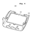
- Figure 4 an illustration of a glass for a telephone according to the invention, the glass is in two parts.
- the top of the telephone mobile and its components is located towards the speaker, the bottom of the mobile phone and its components is located towards the mobile phone microphone.
- the front part of the telephone or of its constituent elements is what the user sees when he looks the mobile phone screen.
- Figure 1 shows a mobile phone 100 having a shell 101 superior.
- the upper shell 101 has a location which is occupied by a window 102.
- These elements shown in FIG. 1 are seen according to a cross section of the telephone 100 at the level of a device for fixing the window 102 to the upper shell 101.
- FIG. 1 also shows a lower shell 103 and a cover 104 of drums. When elements 101 to 104 are assembled, they constitute the 100 mobile phone case.
- the window 102 is composed of two elements.
- the window 102 comprises a tile 105 and a faceplate 106.
- the window 105 is then welded to the front plate 106.
- the telephone user mobile 100 can see a screen from their mobile phone.
- Glass 102 also has two tabs 107 and 108.
- the tabs 107 and 108 are located on the side edges of the window 102. This is a small outgrowth thickness which are perpendicular to the plane of the tile 105.
- the tabs 107 and 108 of the glass 102 are inside this case.
- the length of the tabs 107 and 108 is sufficient so that when the battery cover 104 is removed from the phone 100 case, a user can reach the end of the tabs 107 and 108 located opposite the tile 105.
- the tabs 107 and 108 have lugs 109 and 110.
- the pins 109 and 110 are located at the ends of the tabs 107 and 108 which are opposite the pane 105.
- the pins are positioned on the faces of the tabs that are facing the outside of the 100 phone case. This positioning is interesting because it facilitates the extraction of the window 102 from the phone case 100. Indeed, to release the window 102 then it suffices to pinch the two tabs 107 and 108 to release the pins.
- the upper shell 101 has elements 111 and 112 located at with respect to the tabs 107 and 108 respectively. When the window 102 is in place on the shell 101, the elements 111 and 112 hook the lugs 109 and 110 respectively.
- the lugs 109 and 110 are bevelled, the lugs are locating down the mobile phone. This is useful for the introduction of the window 102 in its location on the shell 101. Indeed these bevels allow you to simply press on the window 102 to introduce it in its location. These bevels prevent that during the introduction of the glass in its location, the lugs 109 and 110 hang on the elements 111 and 112. When the window 102 is inserted into the shell 101, the tabs 107 and 108 are therefore deformed, they resume their shape original when the window is fully pushed into its place the lugs 109 and 110 are then hooked to the elements 111 and 112.
- Figure 1 shows that on the lower shell 103 is fixed a cover 104 of battery.
- This cover has an anti-kickback device composed of two well respectively 113 and 114.
- the window 102 When the window 102 is in place on the phone case 100, the end of the tab 109 is housed in the well 113 and the end of the tongue 108 is housed in the well 114. It is no longer possible for the tabs 107 and 108 to deform enough to allow lugs 109 and 110 to detach from elements 111 respectively 112. Indeed during a deformation which would occur, following a shock for example, the deformation of the tongues would be limited by the walls of wells 113 and 114. Once the battery is placed on the mobile phone 100, the window 102 is therefore locked.
- Figure 2 shows a side view of a mobile phone according to the invention.
- Figure 1 shows an upper shell 101, the window 102 comprising a faceplate 106 and a window 105.
- Figure 2 also shows the lower shell 103 and battery cover 104.
- the window 102 has in its upper part a lug 201 which comes be housed under the shell 101.
- the window 102 also includes a lever 202 which is supported by items in phone 100, but not shown in Figure 2, and allows when putting in place the window 102 to press the lug 201 against the hull 101.
- the assembly 201-202 contributes therefore maintaining the window 102 in place.
- Figure 2 also shows that the tongue is wide enough to accommodate lug 109, and not undergo deformation in one direction materialized by a straight line that goes from the top of the phone to the bottom of the phone.
- the lug 109 is hollowed out in its central part in order to achieve a economy of material, while keeping it wide enough to ensure its robustness and good grip on the element 111.
- the lug 109 is consisting of a parallelepiped with the largest side of the stop greenhouse on item 111, and two right triangles below it and each side of the parallelepiped. These triangles reinforce the parallelepiped and facilitates the insertion of the window 102 into its location.
- FIG. 3 shows a window 300 for a telephone according to the invention.
- the window 300 comprises lugs 201 and 301, as well as levers 202 and 302.
- a user positions the lugs 201 and 301 in the locations provided for this effect on a top shell of the phone. Then the user places the tabs 107 and 108 in the slots provided for this purpose in the upper shell of the telephone and press on the front face of the glass 300.
- the levers 202 and 302 will then take support on the elements contained in the mobile phone which will press the pins 201 and 301 against the phone shell.
- the tabs 107 and 108 will deform inwards according to a direction 303.
- Figure 3 also shows guides 304 and 305.
- Guides 304 and 305 are located on the rear face of the window 300. These guides have a shape conical in order to facilitate their introduction into locations provided for this effect on the front of the upper shell of the phone. Furthermore this conical shape will facilitate and improve the maintenance of the glass once it implementation.
- the tabs 107 and 108 return to their original shape and the pins 109 and 110 are then hooked to elements of the upper shell.
- the establishment of the glass can only be done if the battery is not attached to the phone.
- element 111 will push back lug 109 which has the effect of deforming the tab 107.
- the end of the tab 107 is collides with the walls of well 113, which stops the introduction of the glass before it's hung. To be able to continue the introduction, unhook the cover 104.
- the case described has two shells, a top and a because it is a practical embodiment for setting up places internal parts of the phone.
- the invention remains valid with a different case. It suffices that the tabs described for the interchangeable glass are accessible from the back of the phone, and locked by a removable element of this phone, in our example preferred a battery.
- pins 109 and 110 on the faces of the tabs 107 and 108 which are oriented towards the outside of the telephone case 100 is justified by the fact that it is easier to pinch than to move aside. However all placement combinations are possible for the pins on the different faces of the tabs 107 and 108, provided that the positions of elements 111 and 112, and wells 113 and 114.
- the window 300 also has a seal 304 located on its inner face and which surrounds a screen of the mobile phone. This seal ensures the tightness of the mobile phone against dust that exists in the environment phone usage. The elasticity of this joint also allows better press pins 109 and 110 against the elements to which they are attached, and therefore improve the maintenance of the window 300.
- Figure 4 shows a window 400 which has the same elements than glass 300. The difference is that glass 400 is made in two elements.
- Figure 4 shows a tile 105 and a front plate 106. This mode of realization allows to realize the plastron and the tile in two materials different, therefore to obtain a glass at lower cost but having a less good rendered.
- the tile 105 is welded to the faceplate 106, by ultrasound for example.
- the glass is larger than the screen that it protects. It is therefore possible to customize the parts of the glass which do not need to be transparent, i.e. which are not in look of the glass, by screen printing them for example.
Landscapes
- Engineering & Computer Science (AREA)
- Signal Processing (AREA)
- Telephone Set Structure (AREA)
Applications Claiming Priority (2)
| Application Number | Priority Date | Filing Date | Title |
|---|---|---|---|
| FR9911821A FR2798799B1 (fr) | 1999-09-22 | 1999-09-22 | Telephone mobile comportant une vitre amovible |
| FR9911821 | 1999-09-22 |
Publications (2)
| Publication Number | Publication Date |
|---|---|
| EP1087592A1 true EP1087592A1 (de) | 2001-03-28 |
| EP1087592B1 EP1087592B1 (de) | 2003-10-22 |
Family
ID=9550107
Family Applications (1)
| Application Number | Title | Priority Date | Filing Date |
|---|---|---|---|
| EP20000402630 Expired - Lifetime EP1087592B1 (de) | 1999-09-22 | 2000-09-21 | Mobiltelefon mit einer beweglicher Fensterscheibe |
Country Status (3)
| Country | Link |
|---|---|
| EP (1) | EP1087592B1 (de) |
| DE (1) | DE60006050T2 (de) |
| FR (1) | FR2798799B1 (de) |
Citations (5)
| Publication number | Priority date | Publication date | Assignee | Title |
|---|---|---|---|---|
| GB2293517A (en) * | 1994-09-20 | 1996-03-27 | Motorola Inc | Portable telephone adapted to accommodate a plurality of distinctive appearances |
| US5745566A (en) * | 1996-10-15 | 1998-04-28 | Motorola, Inc. | Portable communication device having removable escutcheon elements |
| US5768370A (en) * | 1997-01-08 | 1998-06-16 | Nokia Mobile Phones, Ltd. | User changeable cosmetic phone interface |
| EP0920166A2 (de) * | 1997-11-28 | 1999-06-02 | Nokia Mobile Phones Ltd. | Funktelefon |
| EP0939533A2 (de) * | 1998-02-27 | 1999-09-01 | Nokia Mobile Phones Ltd. | Verschiebbarer Deckel für ein Kommunikationseinheit |
-
1999
- 1999-09-22 FR FR9911821A patent/FR2798799B1/fr not_active Expired - Fee Related
-
2000
- 2000-09-21 EP EP20000402630 patent/EP1087592B1/de not_active Expired - Lifetime
- 2000-09-21 DE DE2000606050 patent/DE60006050T2/de not_active Expired - Lifetime
Patent Citations (5)
| Publication number | Priority date | Publication date | Assignee | Title |
|---|---|---|---|---|
| GB2293517A (en) * | 1994-09-20 | 1996-03-27 | Motorola Inc | Portable telephone adapted to accommodate a plurality of distinctive appearances |
| US5745566A (en) * | 1996-10-15 | 1998-04-28 | Motorola, Inc. | Portable communication device having removable escutcheon elements |
| US5768370A (en) * | 1997-01-08 | 1998-06-16 | Nokia Mobile Phones, Ltd. | User changeable cosmetic phone interface |
| EP0920166A2 (de) * | 1997-11-28 | 1999-06-02 | Nokia Mobile Phones Ltd. | Funktelefon |
| EP0939533A2 (de) * | 1998-02-27 | 1999-09-01 | Nokia Mobile Phones Ltd. | Verschiebbarer Deckel für ein Kommunikationseinheit |
Also Published As
| Publication number | Publication date |
|---|---|
| EP1087592B1 (de) | 2003-10-22 |
| DE60006050T2 (de) | 2004-06-03 |
| FR2798799A1 (fr) | 2001-03-23 |
| DE60006050D1 (de) | 2003-11-27 |
| FR2798799B1 (fr) | 2002-05-31 |
Similar Documents
| Publication | Publication Date | Title |
|---|---|---|
| EP0013718A1 (de) | Drehbar gelagerter Träger für gedruckte Schaltungen | |
| CH672662A5 (de) | ||
| EP1087592B1 (de) | Mobiltelefon mit einer beweglicher Fensterscheibe | |
| FR2709032A1 (fr) | Système de verrouillage. | |
| EP2638821A1 (de) | Schutzhülle eines tragbaren elektronischen Geräts | |
| EP2112734B1 (de) | Elektrogerät zum Aufsetzen auf ein Einbaugehäuse | |
| FR2808570A1 (fr) | Ensemble de connexion a verrouillage du type baionnette | |
| FR2719818A1 (fr) | Dispositif pour l'insertion d'un composant électronique sur la clé d'un véhicule, et clé munie de ce dispositif. | |
| FR2839819A1 (fr) | Boitier a brides pour cloisons creuses | |
| EP3840136A1 (de) | Mechanismus eines elektrischen geräts, entsprechende elektrische anordung und entsprechendes elektrisches gerät | |
| FR3024343A1 (fr) | Systeme de protection pour dispositif de communication mobile et procede d'installation de ce systeme de protection | |
| FR2501953A1 (fr) | Carrosserie pour appareil a tube ecran et clavier | |
| EP1008813A1 (de) | Vorrichtung zum Anbringen einer Schutzhülle auf einer ebenen Fläche | |
| EP0342095A1 (de) | Vorrichtung zum mechanischen Schützen einer Leiterplatte, insbesondere eines Chassis eines Farbfernsehgeräts | |
| FR2759871A1 (fr) | Etui pour telephone portable | |
| EP0443885A1 (de) | Befestigungsvorrichtung für einen Induktivdetektor an einer Maschine | |
| EP3026686B1 (de) | Schutzvorrichtung gegen wasserinfiltration und staub in einem elektronischen gerät, und herstellungsverfahren einer solchen vorrichtung | |
| EP1351474B1 (de) | Schokprotecktionsvorrichtung für Wandlerkapsel eines Telefonhandapparats | |
| EP3381072B1 (de) | Abnehmbare klappe zum schliessen einer stelle zur aufnahme von mindestens einer batterie einer elektronischen vorrichtung und entsprechende elektronische vorrichtung | |
| EP0893903A1 (de) | Ziehhilfe für Batteriesatz in einem Telefongerät | |
| FR2728865A1 (fr) | Conteneurs pour un ilot de sauvetage avec systeme de fixation | |
| KR20120124299A (ko) | 디스플레이 개폐장치 | |
| EP1887169B1 (de) | Elektrisches Schließblech | |
| EP1096820A1 (de) | Mobiltelefon mit einer lösbare Verbindung zwischen sein Gehäuse und sein Batteriegehäuse | |
| FR2791842A1 (fr) | Appareil telephonique mobile a volet de protection |
Legal Events
| Date | Code | Title | Description |
|---|---|---|---|
| PUAI | Public reference made under article 153(3) epc to a published international application that has entered the european phase |
Free format text: ORIGINAL CODE: 0009012 |
|
| AK | Designated contracting states |
Kind code of ref document: A1 Designated state(s): DE FR GB |
|
| AX | Request for extension of the european patent |
Free format text: AL;LT;LV;MK;RO;SI |
|
| RAP1 | Party data changed (applicant data changed or rights of an application transferred) |
Owner name: SAGEM S.A. |
|
| 17P | Request for examination filed |
Effective date: 20010920 |
|
| AKX | Designation fees paid |
Free format text: DE FR GB |
|
| 17Q | First examination report despatched |
Effective date: 20020205 |
|
| GRAH | Despatch of communication of intention to grant a patent |
Free format text: ORIGINAL CODE: EPIDOS IGRA |
|
| GRAS | Grant fee paid |
Free format text: ORIGINAL CODE: EPIDOSNIGR3 |
|
| GRAA | (expected) grant |
Free format text: ORIGINAL CODE: 0009210 |
|
| AK | Designated contracting states |
Kind code of ref document: B1 Designated state(s): DE FR GB |
|
| REG | Reference to a national code |
Ref country code: GB Ref legal event code: FG4D Free format text: NOT ENGLISH |
|
| REF | Corresponds to: |
Ref document number: 60006050 Country of ref document: DE Date of ref document: 20031127 Kind code of ref document: P |
|
| GBT | Gb: translation of ep patent filed (gb section 77(6)(a)/1977) |
Effective date: 20040308 |
|
| PLBE | No opposition filed within time limit |
Free format text: ORIGINAL CODE: 0009261 |
|
| STAA | Information on the status of an ep patent application or granted ep patent |
Free format text: STATUS: NO OPPOSITION FILED WITHIN TIME LIMIT |
|
| 26N | No opposition filed |
Effective date: 20040723 |
|
| REG | Reference to a national code |
Ref country code: FR Ref legal event code: CA Ref country code: FR Ref legal event code: TP Ref country code: FR Ref legal event code: CD |
|
| PGFP | Annual fee paid to national office [announced via postgrant information from national office to epo] |
Ref country code: GB Payment date: 20090827 Year of fee payment: 10 |
|
| PGFP | Annual fee paid to national office [announced via postgrant information from national office to epo] |
Ref country code: DE Payment date: 20091008 Year of fee payment: 10 |
|
| REG | Reference to a national code |
Ref country code: FR Ref legal event code: TP |
|
| PGFP | Annual fee paid to national office [announced via postgrant information from national office to epo] |
Ref country code: FR Payment date: 20091021 Year of fee payment: 10 |
|
| GBPC | Gb: european patent ceased through non-payment of renewal fee |
Effective date: 20100921 |
|
| REG | Reference to a national code |
Ref country code: FR Ref legal event code: ST Effective date: 20110531 |
|
| REG | Reference to a national code |
Ref country code: DE Ref legal event code: R119 Ref document number: 60006050 Country of ref document: DE Effective date: 20110401 |
|
| PG25 | Lapsed in a contracting state [announced via postgrant information from national office to epo] |
Ref country code: FR Free format text: LAPSE BECAUSE OF NON-PAYMENT OF DUE FEES Effective date: 20100930 Ref country code: DE Free format text: LAPSE BECAUSE OF NON-PAYMENT OF DUE FEES Effective date: 20110401 |
|
| PG25 | Lapsed in a contracting state [announced via postgrant information from national office to epo] |
Ref country code: GB Free format text: LAPSE BECAUSE OF NON-PAYMENT OF DUE FEES Effective date: 20100921 |
|
| REG | Reference to a national code |
Ref country code: GB Ref legal event code: 732E Free format text: REGISTERED BETWEEN 20120426 AND 20120502 |
|
| REG | Reference to a national code |
Ref country code: GB Ref legal event code: 732E Free format text: REGISTERED BETWEEN 20120503 AND 20120509 |