EP1087796B1 - Procede de traitement de la phase liquide de substances contaminees - Google Patents
Procede de traitement de la phase liquide de substances contaminees Download PDFInfo
- Publication number
- EP1087796B1 EP1087796B1 EP99939353A EP99939353A EP1087796B1 EP 1087796 B1 EP1087796 B1 EP 1087796B1 EP 99939353 A EP99939353 A EP 99939353A EP 99939353 A EP99939353 A EP 99939353A EP 1087796 B1 EP1087796 B1 EP 1087796B1
- Authority
- EP
- European Patent Office
- Prior art keywords
- liquid
- treatment chamber
- collection container
- container
- taken
- Prior art date
- Legal status (The legal status is an assumption and is not a legal conclusion. Google has not performed a legal analysis and makes no representation as to the accuracy of the status listed.)
- Expired - Lifetime
Links
Images
Classifications
-
- A—HUMAN NECESSITIES
- A61—MEDICAL OR VETERINARY SCIENCE; HYGIENE
- A61L—METHODS OR APPARATUS FOR STERILISING MATERIALS OR OBJECTS IN GENERAL; DISINFECTION, STERILISATION OR DEODORISATION OF AIR; CHEMICAL ASPECTS OF BANDAGES, DRESSINGS, ABSORBENT PADS OR SURGICAL ARTICLES; MATERIALS FOR BANDAGES, DRESSINGS, ABSORBENT PADS OR SURGICAL ARTICLES
- A61L2/00—Disinfection or sterilisation of materials or objects, in general; Accessories therefor
- A61L2/02—Disinfection or sterilisation of materials or objects, in general; Accessories therefor using physical processes
- A61L2/04—Heat
-
- A—HUMAN NECESSITIES
- A61—MEDICAL OR VETERINARY SCIENCE; HYGIENE
- A61L—METHODS OR APPARATUS FOR STERILISING MATERIALS OR OBJECTS IN GENERAL; DISINFECTION, STERILISATION OR DEODORISATION OF AIR; CHEMICAL ASPECTS OF BANDAGES, DRESSINGS, ABSORBENT PADS OR SURGICAL ARTICLES; MATERIALS FOR BANDAGES, DRESSINGS, ABSORBENT PADS OR SURGICAL ARTICLES
- A61L11/00—Methods specially adapted for refuse
Definitions
- the invention relates to a method for treating the liquid phase of contaminated, in particular infected materials, which are affected by an input unit extending in a treatment chamber of a high temperature disinfection device Transport system supplied, heated and disinfected or sterilized as well as on one Ejection are discharged, with a defined collection area for liquid on Feed end of the transport system is provided in the treatment chamber.
- the invention further relates to a device for the treatment of contaminated, in particular of infected materials, in which they are affected by an input unit in a treatment chamber extending transport system supplied, heated and disinfected or sterilized and carried out on an expectoration, whereby a Defined collection area for liquid at the feed end of the transport system in the Treatment chamber is provided.
- US-A-5 759 491 discloses a method for the treatment of infected materials discloses, in which the material to be treated via a collection area Transport system is supplied, which extends through the treatment chamber. There heating, sterilization and disinfection take place. The treated mud is paid off at the discharge. Liquid can flow from a collection container into the Pumped area pumped or removed and conveyed into the collection container become.
- EP-A-0 672 426 shows an apparatus for treating infected waste. Doing so the initially shredded waste in a liquid disinfected liquid fed. This liquid is passed through a pelletizing and disinfection station subsequent drainage station provided. This will result in a return of disinfected liquid reached.
- DE 41 38 939 finally shows a device and a method for sterilizing and Disinfect contaminated hospital waste.
- the granulated garbage then becomes one Disinfection screw fed and dried. Then treatment with Saturated steam and drying again.
- the object of the invention is therefore to provide a method with which even large amounts of purely liquid waste accumulating in a short time are independent of the actual treatment line provided for solid waste material High temperature disinfection device can be treated safely. Furthermore, the Invention, the object of the treatment of contaminated, in particular infected materials, which have a liquid and a solid phase, a device to ensure that even large amounts of pure liquid waste accumulate in a short time disinfect or sterilize allowed.
- liquid from the collection container is returned to the treatment chamber only when the liquid level in the Treatment chamber has reached a predetermined minimum value. It means that, when the liquid level in the collection container reaches the predetermined maximum value usually has liquid from the collection container in the additional high-temperature disinfection unit or sterilization unit for pure liquid is treated.
- the high-temperature disinfection unit can essentially consist of a heat exchanger exist in which the liquid to be treated is at least at a temperature heated and this temperature is maintained for as long as is necessary for disinfection or is required for sterilization.
- Disinfection or sterilization using the heat exchanger can be carried out continuously, by creating a permanent overpressure in the heat exchanger in that the Flow of treated liquid leaving the heat exchanger via a throttle element of this type is reduced that in the case of feeding by means of a pump in the heat exchanger Pressure builds up.
- a heat exchanger is available as an additional high-temperature disinfection unit and liquid from the collection container into the treatment chamber only then is returned when the liquid level in the treatment chamber is one predetermined minimum value is reached, i.e. liquid from the collection container Reaching a maximum value is passed through the heat exchanger -, is preferably provided that the collection container only up to about the heat exchanger a predetermined liquid level mean is emptied. That way achieved that there is always enough liquid in the collection container to the Liquid level in the treatment chamber when the specified one is reached Minimum values without being able to increase fresh water supply.
- the liquid in the collecting container can be disinfected or sterilized, i.e. the additional high-temperature disinfection unit is given by the collection container itself, and that in this case further untreated liquid can be collected in a buffer container that is arranged between the treatment chamber and the collecting container. In this case there is no need for the downstream heat exchanger.
- the defined collection area for liquid the Treatment chamber is created in that the treatment chamber in Delivery direction is inclined upwards. In this case, it gathers in the Treatment chamber introduced liquid in a lower, by the inclination predetermined area of the treatment chamber.
- the transport system is also based preferably on one or more screw conveyors.
- the object of the invention is achieved with respect to the device by a generic Device solved, which additionally has the feature that the collection area of Treatment chamber with at least one liquid line Liquid collection container is connected such that liquid from the collection area the treatment chamber into the collection container and from this back into the Treatment chamber can be performed.
- the treatment chamber can be changed. So when a maximum value is reached is. Liquid is led from the treatment chamber into the liquid collection container to reduce the amount of fluid in the treatment chamber. on the other hand may also be when the liquid level in the treatment chamber is at a minimum reached, liquid is returned from the collection container to the treatment chamber be to ensure that there is sufficient liquid in this to produce the necessary steam pressure is present.
- the liquid collection container with an in addition to Treatment chamber existing high-temperature disinfection unit or sterilization unit is connected via a liquid line. This ensures that at all times Liquid can be removed from the liquid collection container to empty it, this liquid regardless of the actual treatment process in the Treatment chamber can be disinfected or sterilized.
- the liquid so treated can be pumped directly into a sewage pipe.
- This additional high-temperature disinfection unit or sterilization unit can be opened based on a heat exchanger.
- the liquid collection container itself as the additional high-temperature disinfection unit or sterilization unit is designed.
- the liquid collection container itself as the additional high-temperature disinfection unit or sterilization unit is designed.
- the liquid collection container itself as the additional high-temperature disinfection unit or sterilization unit is designed.
- a buffer container for further untreated liquid discharged from the treatment chamber is arranged. Liquid can flow into the treatment chamber from this buffer container as required to be led back.
- Both the liquid collection container and the buffer container can be ventilated or work on the principle of a wind boiler. While in the former case! a pump necessary is. in order to discharge liquid from the collection container, the after Principle of a liquid boiler working by an air boiler by feeding Liquid builds up in this overpressure, which when opening an outlet of the Liquid collection container expels liquid from it. Even with one Liquid collection tank, which is based on the principle of a wind boiler, can additionally a ventilation option can be provided to ensure complete emptying of the To facilitate liquid collection container. The same applies to the buffer tank.
- the treatment chamber is preferably directed upwards in the conveying direction in order to this way the defined collection area for liquid in the treatment chamber produce. Furthermore, it is preferably provided that the transport system one or has a plurality of screw conveyors which extend within the treatment chamber.
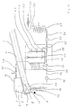
- the device according to FIG. 1 - designated by reference number 1 - has one Treatment chamber 2 (only partially shown). Essentially across the whole The length of a first section of the treatment chamber 2 extends to a not shown Auger.
- the heating screw is one over most of its length Provided double jacket 3, in which there is heat transfer oil, which is in a not shown Heating block is heated.
- the device 1 also has an input unit 4 with a lower hopper 5 and a Dispenser 6 on. Below the input unit 4, namely at the feed end of the by Heating screw given the transport system, there is a defined collection area 7 for liquid, which together with contaminated solids in the lower funnel 5 are given.
- the defined collection area 7 results on the one hand from the predetermined inclination of the treatment chamber 2 and on the other hand from a Liquid detector 8 of a predetermined maximum liquid level in the Treatment chamber 2 defines.
- a liquid drain 10 of the treatment chamber 2 is located below the Liquid detector 9.
- the liquid drain 10 is through a sieve 11 of the Heating screw separately.
- another Liquid detector 12 arranged, which provides a signal, if no liquid at all there is more in the treatment chamber 2.
- a pipe 13 is connected via a connection 14 to the liquid outlet 10 and leads to a collection container 15 for liquid.
- the collecting container 15 is arranged in a housing 18 which has a switch box 19 Furthermore, the collecting container 15 with an agitator 20 and three Level indicators 21 22 and 23 equipped.
- a ventilation line 24 with a Electric valve 25 connects the lower hopper 5 and the top of the Collecting container 15.
- Another pipe 26 leads from the bottom of the collecting container 15 to one Heat exchanger 27.
- an electric ball valve 28 and an unloading pump 29 is arranged on the output side.
- the heat exchanger 27 is connected to a further pipeline 30 connected, which has a throttle and shut-off valve 31 and for example, leads to a conventional sewage pipe.
- the device 1 for the treatment of contaminated materials based on the following functionality.
- Contaminated material is removed via the input unit 4 of the heating screw extends within the first section of the treatment chamber 2. While The material to be treated is defined during transportation by the heating screw heated. The heating screw also compresses the material in the Form that a sealing plug of material is generated in the end region. At the end the heating screw is a second section (not shown) of the treatment chamber arranged in which a relaxation and loosening of the structure of the treated Material. In the second section of the treatment chamber is a second one Conveyor screw arranged to which the material is fed through the heating screw. The second screw conveyor is as a treatment screw surrounded by a heating element for trained the material.
- the treatment screw compresses the material in its end area to a second sealing Material plug, such that between the two material plugs acting as a seal the snails the overpressure can be kept for a defined period of time. At the At the end of the treatment screw there is an expectoration for the treated material.
- liquid level in the collection area 7 of the Treatment chamber 2 is not below that specified by the liquid detector 9 Minimum value drops. On the other hand, it should be ensured that the liquid level is not exceeds the maximum value specified by the liquid detector 8.
- the ball valve 17 When the liquid detector 8 indicates that the maximum value of the liquid level in the Collection area 7 is reached, the ball valve 17 is opened and through the Positive displacement pump 16 liquid from the collecting area 7 into the collecting container 15 promoted. This continues until the liquid level in the collection area 7 Minimum value reached. The ball valve 17 is then closed again. About the Aeration line, the collecting container 15 is ventilated.
- the ball valve 28 is opened and 29 liquid in the discharge pump Heat exchanger 27 out. However, this only happens until in the collection container 15 the level specified by the level indicator 22 has been reached. This will ensures that there is always enough liquid in the collection container 15 for recycling is present in the treatment chamber 2.
- the sterilization process in the heat exchanger 27 can be both continuous and done discontinuously. In discontinuous operation, this will be at the end of the Heat exchanger 27 located shut-off valve 31 closed, and by the Discharge pump 29 liquid under pressure in the heat exchanger 27 remains for the minimum residence time in the heat exchanger for safe sterilization. The shut-off valve 31 is then opened and the sterilized liquid is expelled conveyed to the heat exchanger 27.
- the valve 31 is used as a throttle element, the Discharge pump 29 permanently in the heat exchanger 27 liquid from the Collected container 15 and fed out behind the throttle valve 31. This however, continuous operation is suspended if the fluid level in the Collection container 15 reaches the height given by the level indicator 22.
- the Continuous sterilization operation through the heat exchanger 27 are the parameters set that each liquid particle from entering the heat exchanger 27 to Exit behind the throttle valve 31 remains in the heat exchanger 27 for a sufficiently long time.
- There is a check valve between the discharge pump 29 and the heat exchanger 27 (not shown) provided to backflow from the heat exchanger 27 Avoid stationary discharge pump 29 in the collection container 15 safely.
- the heat exchanger 27 can be heated in a parallel flow by the same heat transfer oil be that for heating the treatment chamber 2 or the heating screw is provided.
- a collection container based on the principle of the wind boiler can also be used.
- a pressure is created by the introduction of liquid built up inside the collection container, which is used to discharge liquid.
- ventilation can be carried out via the ventilation line 24 when a rapid complete emptying of the collecting container is to be carried out.
- ventilation line 24 can also be dispensed with in this case. If the Collecting container works on the wind boiler principle, one can also use the Connection container connected pressure source may be provided for an additional possibility to create overpressure in the collection container.
- the Pipeline 13 is used only for supplying liquid into the collecting container 15 and for returning liquid from the collection container 15 into the Treatment chamber 2 another line is provided.
- the pump 16 as a pump that only works in one direction
- the valve 17 as a check valve be designed.
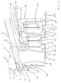
- FIG. 2 In this figure is another one Device 32 according to the invention shown.
- This device 32 differs from that Device 1 shown in FIG. 1 essentially in that a further container 33 is provided between the treatment chamber 2 and the collecting container 15 is arranged and serves as a buffer tank.
- the buffer tank 33 and the collecting tank 15 are connected to one another via a further pipeline 34.
- a further ball valve 35 and a further displacement pump 36 are arranged.
- the buffer tank 33 is connected to the ventilation line 38 via a valve 37 Ventilation line 24 connected.
- the buffer container 33 also has an agitator 39. Both containers 33 and 15 are each provided with a level indicator 40 or 41, each with a minimum Specify the fill level and a maximum fill level of the container.
- the collection container 15 is designed so that in addition to the in Figure 1 shown heat exchanger 27 autoclaved the contaminated liquid in it can be. During this sterilization process, more can be removed from the Collection area 7 of the treatment chamber 2 liquid to be removed in the Buffer container 33 can be collected, or liquid can be removed from the buffer container 33 be returned to the treatment chamber 2.
- the two containers 35 and 15 can operate on the principle of one Wind boilers are used working.
Landscapes
- Health & Medical Sciences (AREA)
- Epidemiology (AREA)
- Life Sciences & Earth Sciences (AREA)
- Animal Behavior & Ethology (AREA)
- General Health & Medical Sciences (AREA)
- Public Health (AREA)
- Veterinary Medicine (AREA)
- Apparatus For Disinfection Or Sterilisation (AREA)
- Heat Treatment Of Water, Waste Water Or Sewage (AREA)
Claims (14)
- Procédé de traitement de la phase liquide de substances contaminées, notamment infectées, qui sont amenées par l'intermédiaire d'une unité d'entrée (4) à un système de transport s'étendant dans une chambre de traitement (2) d'un dispositif de désinfection à haute température, chauffées et désinfectées ou stérilisées, ainsi qu'évacuées au niveau d'une sortie, une zone de collecte définie (7) pour du liquide étant prévue dans la chambre de traitement (2) au niveau de l'extrémité d'amenée du système de transport, caractérisé en ce quedu liquide qui s'est accumulé dans la zone de collecte définie (7) de la chambre de traitement (2) est évacué dans un récipient collecteur (15) lorsqu'un niveau maximal de liquide est atteint,lorsque le niveau de liquide dans la chambre de traitement (2) atteint une valeur minimale prédéterminée, du liquide est ramené du récipient collecteur (15) dans la chambre de traitement (2),lorsque le niveau de liquide dans le récipient collecteur (15) atteint une valeur maximale prédéterminée, du liquide est ramené du récipient collecteur (15) dans la chambre de traitement (2) si le niveau maximal de liquide n'est pas atteint dans la chambre de traitement (2), et/ou est traité dans une autre unité de désinfection à haute température (27) destinée à du liquide pur.
- Procédé selon la revendication 1, caractérisé en ce que le liquide du récipient collecteur (15), qui est à traiter dans l'unité de désinfection à haute température destiné à du liquide pur, passe dans un echangeur de chaleur (27) dans lequel il est au moins porté à une température et maintenu à cette température aussi longtemps que cela est nécessaire pour une désinfection ou une stérilisation.
- Procédé selon la revendication 2, caractérisé en ce que la désinfection ou la stérilisation au moyen de l'échangeur de chaleur (27) est effectuée en continu, une surpression permanente étant engendrée dans l'échangeur de chaleur (27) par le fait que le flux de liquide traité sortant de l'échangeur de chaleur (27) est limité par un organe de restriction (31).
- Procédé selon la revendication 2 ou 3, caractérisé en ce que, dans le cas où du liquide du récipient collecteur (15) n'est ramené dans la chambre de traitement (2) que lorsque le niveau de liquide dans la chambre de traitement (2) a atteint une valeur minimale prédéterminée, du liquide est évacué du récipient collecteur (15) par l'échangeur de chaleur (27) jusqu'à ce que le niveau de liquide dans le récipient collecteur (15) ait atteint une valeur moyenne prédéterminée.
- Procédé selon la revendication 1, caractérisé en ce que le liquide à traiter dans l'autre unité de désinfection à haute température est désinfecté ou stérilisé dans le récipient collecteur (15), notamment au cours d'un processus de désinfection ou de stérilisation dans le récipient collecteur (15), et en ce que du liquide supplémentaire non traité est collecté dans un récipient tampon (33) qui est disposé entre la chambre de traitement (2) et le récipient collecteur (15).
- Procédé selon l'une quelconque des revendications précédentes, caractérisé en ce que la zone de collecte définie (7) pour du liquide est créée par le fait que la chambre de traitement (2) est inclinée vers le haut dans le sens du transport.
- Procédé selon l'une quelconque des revendications précédentes, caractérisé en ce que le système de transport comporte un transporteur à vis.
- Dispositif destiné à la mise en oeuvre du procédé de traitement de substances contaminées, notamment infectées, selon les revendications 1 à 7, dans lequel celles-ci sont amenées par l'intermédiaire d'une unité d'entrée (4) à un système de transport s'étendant dans une chambre de traitement (2), chauffées et désinfectées ou stérilisées, ainsi qu'évacuées au niveau d'une sortie, une zone de collecte définie (7) pour du liquide étant prévue dans la chambre de traitement (2) au niveau de l'extrémité d'amenée du système de transport, caractérisé en ce que , par l'intermédiaire d'au moins une conduite (13) de liquide, la zone de collecte (7) de la chambre de traitement (2) est reliée à un récipient collecteur (15) de liquide, de telle sorte que du liquide puisse être amené de la zone de collecte (7) de la chambre de traitement (2) dans le récipient collecteur (15), et ramené de ce dernier dans la chambre de traitement (2), un indicateur de liquide (8, 9) étant prévu pour la détection des niveaux de remplissage respectifs, et en ce que le récipient collecteur (15) de liquide est relié à une autre unité de désinfection à haute température (27) par l'intermédiaire d'une conduite (26) de liquide.
- Dispositif selon la revendication 8, caractérisé en ce que l'autre unité de désinfection à haute température comporte un échangeur de chaleur (27)
- Dispositif selon la revendication 9, caractérisé en ce que le récipient collecteur (15) de liquide est conçu en tant qu'autre unité de désinfection à haute température.
- Dispositif selon la revendication 10, caractérisé en ce qu'un récipient tampon (33) destiné au liquide provenant de la zone de collecte (7) de la chambre de traitement (2) est disposé entre la chambre de traitement (2) et le récipient collecteur (15) de liquide.
- Dispositif selon l'une quelconque des revendications 8 à 11, caractérisé en ce que le récipient collecteur (15) de liquide fonctionne selon le principe d'un réservoir atmosphérique.
- Dispositif selon l'une quelconque des revendications 8 à 12, caractérisé en ce que la chambre de traitement (2) est orientée vers le haut dans le sens du transport.
- Dispositif selon l'une quelconque des revendications 8 à 13, caractérisé en ce que le système de transport comporte un transporteur à vis.
Applications Claiming Priority (3)
| Application Number | Priority Date | Filing Date | Title |
|---|---|---|---|
| DE19827404A DE19827404C1 (de) | 1998-06-19 | 1998-06-19 | Verfahren zur Behandlung der flüssigen Phase von kontaminierten, insbesondere infizierten Materialien und eine Vorrichtung zu dessen Durchführung |
| DE19827404 | 1998-06-19 | ||
| PCT/DE1999/001774 WO1999066963A1 (fr) | 1998-06-19 | 1999-06-16 | Procede de traitement de la phase liquide de substances contaminees |
Publications (2)
| Publication Number | Publication Date |
|---|---|
| EP1087796A1 EP1087796A1 (fr) | 2001-04-04 |
| EP1087796B1 true EP1087796B1 (fr) | 2002-05-15 |
Family
ID=7871439
Family Applications (1)
| Application Number | Title | Priority Date | Filing Date |
|---|---|---|---|
| EP99939353A Expired - Lifetime EP1087796B1 (fr) | 1998-06-19 | 1999-06-16 | Procede de traitement de la phase liquide de substances contaminees |
Country Status (6)
| Country | Link |
|---|---|
| US (1) | US6495095B1 (fr) |
| EP (1) | EP1087796B1 (fr) |
| JP (1) | JP4071935B2 (fr) |
| AT (1) | ATE217534T1 (fr) |
| DE (1) | DE19827404C1 (fr) |
| WO (1) | WO1999066963A1 (fr) |
Families Citing this family (6)
| Publication number | Priority date | Publication date | Assignee | Title |
|---|---|---|---|---|
| BE1014107A3 (fr) * | 2001-12-07 | 2003-04-01 | Chonquerez Alain | Procede de traitement d'effluents liquides et installation prevue a cet effet. |
| FR2835249B1 (fr) * | 2002-01-31 | 2004-11-26 | Nisse | Dispositif de traitement d'effluents liquides issus de laboratoires d'analyses medicales, procede d'utilisation d'un tel dispositif |
| US8268238B2 (en) | 2006-09-29 | 2012-09-18 | Tyco Healthcare Group Lp | System and method for recycling sterilant gas |
| US7666369B2 (en) | 2006-09-29 | 2010-02-23 | Tyco Healthcare Group Lp | System and method for recycling sterilant gas |
| DE102016106746A1 (de) * | 2016-04-12 | 2017-10-12 | Cebcon Technologies Gmbh | Verfahren zum Hygienisieren von Biomasse |
| CN111453256B (zh) * | 2020-04-07 | 2022-03-15 | 吉林大学 | 一种手术室护理中废物收集护理装置 |
Family Cites Families (4)
| Publication number | Priority date | Publication date | Assignee | Title |
|---|---|---|---|---|
| US5425925A (en) * | 1990-04-19 | 1995-06-20 | Winfield Industries, Inc. | Multi-stage infectious waste treatment system |
| DE4138939C2 (de) * | 1991-11-27 | 1994-09-15 | Rainer Ringeisen | Verfahren und Vorrichtung zum Sterilisieren von Krankenhausmüll |
| US5759491A (en) * | 1995-07-21 | 1998-06-02 | Bunin; Kiva | Process and apparatus for the decontamination of infectious waste |
| DE19717839C2 (de) * | 1997-04-26 | 1999-07-29 | Helmut Goeldner | Verfahren zur Behandlung von kontaminierten, insbesondere infizierten Materialien |
-
1998
- 1998-06-19 DE DE19827404A patent/DE19827404C1/de not_active Expired - Fee Related
-
1999
- 1999-06-16 EP EP99939353A patent/EP1087796B1/fr not_active Expired - Lifetime
- 1999-06-16 US US09/719,989 patent/US6495095B1/en not_active Expired - Lifetime
- 1999-06-16 JP JP2000555649A patent/JP4071935B2/ja not_active Expired - Fee Related
- 1999-06-16 WO PCT/DE1999/001774 patent/WO1999066963A1/fr not_active Ceased
- 1999-06-16 AT AT99939353T patent/ATE217534T1/de active
Also Published As
| Publication number | Publication date |
|---|---|
| DE19827404C1 (de) | 1999-11-18 |
| US6495095B1 (en) | 2002-12-17 |
| JP2002518134A (ja) | 2002-06-25 |
| ATE217534T1 (de) | 2002-06-15 |
| EP1087796A1 (fr) | 2001-04-04 |
| WO1999066963A1 (fr) | 1999-12-29 |
| JP4071935B2 (ja) | 2008-04-02 |
Similar Documents
| Publication | Publication Date | Title |
|---|---|---|
| DE69619990T2 (de) | Vorrichtung und verfahren zur behandlung von abfällen | |
| AT401471B (de) | Vorrichtung und verfahren zur behandlung von medizinischen sonderabfällen | |
| DE69810584T2 (de) | Verfahren und Methode zur Behandlung von Abfällen | |
| EP0277507B1 (fr) | Dispositif de désinfection pour ordures ménagères contaminées | |
| EP2709840B1 (fr) | Presse à vis | |
| DE68921487T2 (de) | Vorrichtung und verfahren zur behandlung und entfernung infektiöser abfälle. | |
| DE602004004128T2 (de) | Maschine und verfahren zur behandlung von produkten mit mikrowellen | |
| DD297145A5 (de) | Kontinuierlich und automatisch arbeitende vorrichtung zum entwaessern eines schlamms, insbesondere klaerschlamms | |
| EP0980266B1 (fr) | Procede et dispositif de traitement de materiaux contamines, notamment infectes | |
| DE69004189T2 (de) | Anordnungen zur behandlung menschlichen oder tierischen abfalls mittels mikrowellen. | |
| DE69524125T2 (de) | Verfahren zur örtlichen Kompostierung und Trocknung von organischen Abfallen und dafür gebrauchte Vorrichtung | |
| EP1087796B1 (fr) | Procede de traitement de la phase liquide de substances contaminees | |
| DE2622939A1 (de) | Verfahren und vorrichtung zur verarbeitung faeulniserregender abfaelle | |
| DE2550142C2 (fr) | ||
| DE19833024C2 (de) | Verfahren und Vorrichtung zur Desinfektion oder Sterilisation von infizierten Materialien | |
| DE102013003592A1 (de) | Verfahren und Einrichtung zur Trennung der Dickphase von der Dünnphase bei Schwebkörper enthaltenden Flüssigkeiten | |
| DE2937965A1 (de) | Vorrichtung zur aeroben verottung von muell o.ae. | |
| EP2117936A1 (fr) | Dispositif et procédé pour éliminer des sacs collecteurs de liquide corporel | |
| EP0611333A1 (fr) | Procede et dispositif de traitement de dechets broyables contenant du liquide | |
| EP1695771B1 (fr) | Procédé et appareil pour la préparation de restes de nourriture et/ou de dechets en vue de leur élimination | |
| DE9113557U1 (de) | Vorrichtung zur Aufbereitung von Flüssigkeit enthaltenden, zerkleinerbaren Abfällen | |
| DE19630263C2 (de) | Verfahren und Vorrichtung zum Behandeln von Rechengut aus Abwässern | |
| EP1293128A1 (fr) | Séparateur pour le traitement des parties des corps des animaux, installation avec ledit séparateur et utilisation | |
| WO2021011979A1 (fr) | Procédé de traitement thermochimique ainsi qu'installation de traitement conçue pour celui-ci | |
| DE2130231A1 (de) | Muellschlucker |
Legal Events
| Date | Code | Title | Description |
|---|---|---|---|
| PUAI | Public reference made under article 153(3) epc to a published international application that has entered the european phase |
Free format text: ORIGINAL CODE: 0009012 |
|
| 17P | Request for examination filed |
Effective date: 20001107 |
|
| AK | Designated contracting states |
Kind code of ref document: A1 Designated state(s): AT BE CH FR GB IE LI NL |
|
| GRAG | Despatch of communication of intention to grant |
Free format text: ORIGINAL CODE: EPIDOS AGRA |
|
| 17Q | First examination report despatched |
Effective date: 20010720 |
|
| GRAG | Despatch of communication of intention to grant |
Free format text: ORIGINAL CODE: EPIDOS AGRA |
|
| GRAH | Despatch of communication of intention to grant a patent |
Free format text: ORIGINAL CODE: EPIDOS IGRA |
|
| GRAH | Despatch of communication of intention to grant a patent |
Free format text: ORIGINAL CODE: EPIDOS IGRA |
|
| GRAA | (expected) grant |
Free format text: ORIGINAL CODE: 0009210 |
|
| AK | Designated contracting states |
Kind code of ref document: B1 Designated state(s): AT BE CH FR GB IE LI NL |
|
| PG25 | Lapsed in a contracting state [announced via postgrant information from national office to epo] |
Ref country code: IE Free format text: LAPSE BECAUSE OF FAILURE TO SUBMIT A TRANSLATION OF THE DESCRIPTION OR TO PAY THE FEE WITHIN THE PRESCRIBED TIME-LIMIT Effective date: 20020515 Ref country code: GB Free format text: LAPSE BECAUSE OF FAILURE TO SUBMIT A TRANSLATION OF THE DESCRIPTION OR TO PAY THE FEE WITHIN THE PRESCRIBED TIME-LIMIT Effective date: 20020515 Ref country code: FR Free format text: LAPSE BECAUSE OF FAILURE TO SUBMIT A TRANSLATION OF THE DESCRIPTION OR TO PAY THE FEE WITHIN THE PRESCRIBED TIME-LIMIT Effective date: 20020515 |
|
| REF | Corresponds to: |
Ref document number: 217534 Country of ref document: AT Date of ref document: 20020615 Kind code of ref document: T |
|
| REG | Reference to a national code |
Ref country code: GB Ref legal event code: FG4D Free format text: NOT ENGLISH Ref country code: CH Ref legal event code: EP |
|
| REG | Reference to a national code |
Ref country code: IE Ref legal event code: FG4D Free format text: GERMAN |
|
| GBV | Gb: ep patent (uk) treated as always having been void in accordance with gb section 77(7)/1977 [no translation filed] |
Effective date: 20020515 |
|
| REG | Reference to a national code |
Ref country code: IE Ref legal event code: FD4D Ref document number: 1087796E Country of ref document: IE |
|
| EN | Fr: translation not filed | ||
| PLBE | No opposition filed within time limit |
Free format text: ORIGINAL CODE: 0009261 |
|
| STAA | Information on the status of an ep patent application or granted ep patent |
Free format text: STATUS: NO OPPOSITION FILED WITHIN TIME LIMIT |
|
| 26N | No opposition filed |
Effective date: 20030218 |
|
| PG25 | Lapsed in a contracting state [announced via postgrant information from national office to epo] |
Ref country code: LI Free format text: LAPSE BECAUSE OF NON-PAYMENT OF DUE FEES Effective date: 20030630 Ref country code: CH Free format text: LAPSE BECAUSE OF NON-PAYMENT OF DUE FEES Effective date: 20030630 |
|
| REG | Reference to a national code |
Ref country code: CH Ref legal event code: PL |
|
| REG | Reference to a national code |
Ref country code: NL Ref legal event code: PD Owner name: LOGTECH PATENT AG; CH Free format text: DETAILS ASSIGNMENT: VERANDERING VAN EIGENAAR(S), OVERDRACHT; FORMER OWNER NAME: HELMUT GOELDNER Effective date: 20150908 |
|
| PGFP | Annual fee paid to national office [announced via postgrant information from national office to epo] |
Ref country code: AT Payment date: 20160713 Year of fee payment: 18 |
|
| PGFP | Annual fee paid to national office [announced via postgrant information from national office to epo] |
Ref country code: NL Payment date: 20160630 Year of fee payment: 18 |
|
| PGFP | Annual fee paid to national office [announced via postgrant information from national office to epo] |
Ref country code: BE Payment date: 20160630 Year of fee payment: 18 |
|
| REG | Reference to a national code |
Ref country code: AT Ref legal event code: PC Ref document number: 217534 Country of ref document: AT Kind code of ref document: T Owner name: LOGTECH PATENT AG, CH Effective date: 20170329 |
|
| REG | Reference to a national code |
Ref country code: NL Ref legal event code: MM Effective date: 20170701 |
|
| REG | Reference to a national code |
Ref country code: AT Ref legal event code: MM01 Ref document number: 217534 Country of ref document: AT Kind code of ref document: T Effective date: 20170616 |
|
| PG25 | Lapsed in a contracting state [announced via postgrant information from national office to epo] |
Ref country code: NL Free format text: LAPSE BECAUSE OF NON-PAYMENT OF DUE FEES Effective date: 20170701 |
|
| PG25 | Lapsed in a contracting state [announced via postgrant information from national office to epo] |
Ref country code: AT Free format text: LAPSE BECAUSE OF NON-PAYMENT OF DUE FEES Effective date: 20170616 |
|
| REG | Reference to a national code |
Ref country code: BE Ref legal event code: PD Owner name: LOGTECH PATENT AG; CH Free format text: DETAILS ASSIGNMENT: CHANGE OF OWNER(S), AFFECTATION / CESSION; FORMER OWNER NAME: GOELDNER, HELMUT Effective date: 20150813 Ref country code: BE Ref legal event code: MM Effective date: 20170630 |
|
| PG25 | Lapsed in a contracting state [announced via postgrant information from national office to epo] |
Ref country code: BE Free format text: LAPSE BECAUSE OF NON-PAYMENT OF DUE FEES Effective date: 20170630 |