EP1088211B1 - Systeme et procede de diagnostic acoustique - Google Patents
Systeme et procede de diagnostic acoustique Download PDFInfo
- Publication number
- EP1088211B1 EP1088211B1 EP99926241A EP99926241A EP1088211B1 EP 1088211 B1 EP1088211 B1 EP 1088211B1 EP 99926241 A EP99926241 A EP 99926241A EP 99926241 A EP99926241 A EP 99926241A EP 1088211 B1 EP1088211 B1 EP 1088211B1
- Authority
- EP
- European Patent Office
- Prior art keywords
- diagnostic system
- test object
- test
- quality
- diagnostic
- Prior art date
- Legal status (The legal status is an assumption and is not a legal conclusion. Google has not performed a legal analysis and makes no representation as to the accuracy of the status listed.)
- Expired - Lifetime
Links
- 238000000034 method Methods 0.000 title claims description 19
- 238000012360 testing method Methods 0.000 claims description 74
- 238000004519 manufacturing process Methods 0.000 claims description 17
- 238000004458 analytical method Methods 0.000 claims description 16
- 239000000919 ceramic Substances 0.000 claims description 10
- 238000012545 processing Methods 0.000 claims description 9
- 238000003908 quality control method Methods 0.000 claims description 9
- 238000000605 extraction Methods 0.000 claims description 5
- 239000011521 glass Substances 0.000 claims description 5
- 239000011159 matrix material Substances 0.000 claims description 5
- 230000003750 conditioning effect Effects 0.000 claims description 4
- 238000002405 diagnostic procedure Methods 0.000 claims description 3
- 238000005516 engineering process Methods 0.000 description 31
- 238000005259 measurement Methods 0.000 description 10
- 238000011156 evaluation Methods 0.000 description 6
- 238000003745 diagnosis Methods 0.000 description 5
- 239000008186 active pharmaceutical agent Substances 0.000 description 4
- 230000001133 acceleration Effects 0.000 description 3
- 235000019646 color tone Nutrition 0.000 description 3
- 238000011161 development Methods 0.000 description 3
- 238000007792 addition Methods 0.000 description 2
- 238000013528 artificial neural network Methods 0.000 description 2
- 238000010276 construction Methods 0.000 description 2
- 230000007547 defect Effects 0.000 description 2
- 230000001419 dependent effect Effects 0.000 description 2
- 238000010586 diagram Methods 0.000 description 2
- 230000005284 excitation Effects 0.000 description 2
- 238000001914 filtration Methods 0.000 description 2
- 238000009533 lab test Methods 0.000 description 2
- 230000003321 amplification Effects 0.000 description 1
- 230000008859 change Effects 0.000 description 1
- 238000006243 chemical reaction Methods 0.000 description 1
- 238000007621 cluster analysis Methods 0.000 description 1
- 238000005314 correlation function Methods 0.000 description 1
- 230000002950 deficient Effects 0.000 description 1
- 238000001514 detection method Methods 0.000 description 1
- 238000007689 inspection Methods 0.000 description 1
- 230000010354 integration Effects 0.000 description 1
- 238000011545 laboratory measurement Methods 0.000 description 1
- 239000000203 mixture Substances 0.000 description 1
- 238000003199 nucleic acid amplification method Methods 0.000 description 1
- 238000012805 post-processing Methods 0.000 description 1
- 238000003672 processing method Methods 0.000 description 1
- 238000012552 review Methods 0.000 description 1
- 239000007787 solid Substances 0.000 description 1
- 238000001228 spectrum Methods 0.000 description 1
- 238000010561 standard procedure Methods 0.000 description 1
- 230000008685 targeting Effects 0.000 description 1
- 238000010998 test method Methods 0.000 description 1
- 230000009466 transformation Effects 0.000 description 1
- 238000012795 verification Methods 0.000 description 1
- 238000012800 visualization Methods 0.000 description 1
Images




Classifications
-
- G—PHYSICS
- G01—MEASURING; TESTING
- G01N—INVESTIGATING OR ANALYSING MATERIALS BY DETERMINING THEIR CHEMICAL OR PHYSICAL PROPERTIES
- G01N29/00—Investigating or analysing materials by the use of ultrasonic, sonic or infrasonic waves; Visualisation of the interior of objects by transmitting ultrasonic or sonic waves through the object
- G01N29/44—Processing the detected response signal, e.g. electronic circuits specially adapted therefor
- G01N29/4445—Classification of defects
-
- G—PHYSICS
- G01—MEASURING; TESTING
- G01M—TESTING STATIC OR DYNAMIC BALANCE OF MACHINES OR STRUCTURES; TESTING OF STRUCTURES OR APPARATUS, NOT OTHERWISE PROVIDED FOR
- G01M13/00—Testing of machine parts
- G01M13/02—Gearings; Transmission mechanisms
- G01M13/028—Acoustic or vibration analysis
-
- G—PHYSICS
- G01—MEASURING; TESTING
- G01M—TESTING STATIC OR DYNAMIC BALANCE OF MACHINES OR STRUCTURES; TESTING OF STRUCTURES OR APPARATUS, NOT OTHERWISE PROVIDED FOR
- G01M15/00—Testing of engines
- G01M15/04—Testing internal-combustion engines
- G01M15/12—Testing internal-combustion engines by monitoring vibrations
-
- G—PHYSICS
- G01—MEASURING; TESTING
- G01N—INVESTIGATING OR ANALYSING MATERIALS BY DETERMINING THEIR CHEMICAL OR PHYSICAL PROPERTIES
- G01N29/00—Investigating or analysing materials by the use of ultrasonic, sonic or infrasonic waves; Visualisation of the interior of objects by transmitting ultrasonic or sonic waves through the object
- G01N29/14—Investigating or analysing materials by the use of ultrasonic, sonic or infrasonic waves; Visualisation of the interior of objects by transmitting ultrasonic or sonic waves through the object using acoustic emission techniques
-
- G—PHYSICS
- G01—MEASURING; TESTING
- G01N—INVESTIGATING OR ANALYSING MATERIALS BY DETERMINING THEIR CHEMICAL OR PHYSICAL PROPERTIES
- G01N2291/00—Indexing codes associated with group G01N29/00
- G01N2291/02—Indexing codes associated with the analysed material
- G01N2291/028—Material parameters
- G01N2291/02827—Elastic parameters, strength or force
Definitions
- the invention relates to an acoustic. Diagnostic system for in particular automatic quality control of test objects, especially of motors, ceramics, etc.
- the invention further relates to an acoustic diagnostic method for in particular automatic quality control of Test objects, in particular engines, ceramics, etc.
- test system or test method comes for example in the field of signal acquisition and signal evaluation for use. This is often a mixture of measurement hardware and combine signal processing software with each other, due to the complexity of the context for one knowledge and experience by specialists are required.
- WO 98/01728 is a device for the detection of analog Measurement signals for acoustic diagnosis of test objects known. With the help of vibration sensors from Analog measurement signals are recorded on a test object. On Computer comes with a standard interface card equipped for digitizing the measurement signals serves. A switching signal is used to generate a trigger signal, which can be entered via a preferred serial interface is. A control program in the computer switches over the Trigger signal the input of measurement signals on and off.
- DE 42 07 728 A1 describes a method for quality inspection of test objects in which the test objects to be examined by an external, pulsed excitation for emission are excited by sound waves, at which the emitted Sound waves can be registered in a sound detector and one based on the registered sound Classification of the test objects in at least two quality classes he follows.
- the classification of the sound spectrum of the test objects takes place through a neural network.
- the invention has for its object an acoustic Diagnostic system and procedure to indicate that simple an automated quality check enables.
- the diagnostic system enables due to the acoustic diagnosis thus an automated and freely understandable Quality control, especially in the manufacture of all Products for which an acoustic diagnosis draws conclusions the quality of the products allowed.
- the diagnostic system can acoustic tests, often by specially trained People are carried out, used as often as required become.
- the automatic archiving of the Quality checks also reliable and always traceable review possible.
- An integration of the diagnostic system into one Production process can take place in such a way that Diagnostic system has control means or with Control center is coupled to control a Production process provided for the production of the test object are.
- a clear classification of the test objects can thereby ensuring that the diagnostic system means comprises, based on an input signal of a test object several classifications or based on a test object assigned input signal several features Determine the classification of the test object, whereby the characteristics associated with each characteristic in each case in color be encoded.
- the diagnostic system means for determining redundant features, which includes a Determine correlation of existing characteristics.
- the diagnostic system for quality control of self-excited test objects, especially motors and / or of externally excited test objects, especially glass or Ceramic is provided.
- Fig. 1 shows a schematic diagram of an acoustic Diagnostic system for diagnosing a test object 1, the Quality and / or function should be determined.
- Test object 1 is the one shown in FIG. 1 Embodiment around an electric motor, i.e. for yourself excited test object, which in itself in the operating state swings.
- diagnostic system also externally excited test objects, z. B. ceramics, glass, etc. are checked by a external impulse must vibrate.
- the Signal acquisition is divided into several stages. At the The sensors are at the beginning of the processing chain takes over the conversion of the mechanical quantities, the one Characterize vibration in electrical signals. Of the possible swing path s, speed v and acceleration a the acceleration is usually recorded.
- the Acceleration structure-borne noise signal
- piezoelectric Accelerometers used for the inclusion of the Acceleration (structure-borne noise signal). These become immediate attached to the device under test.
- To determine the airborne sound level serve microphones 2a, which are in the vicinity of the DUT are arranged.
- the next level is the Signal conditioning 3 represents.
- the coming from the sensors electrical signals E are amplified and in a low pass 3b filtered low pass (aliasing).
- the analog measured variables with an AD converter 3c into discrete digital values D for the subsequent computer-based Evaluation implemented.
- the signal processing 4 consists of the signal analysis 4a or feature extraction and Classification 4b.
- the signal analysis 4a obtains characteristic results from the recorded and converted signals, the so-called features by means of which the signals can be described.
- the purpose of the analysis is to reduce the data of the measured values without losing relevant information about the test object.
- the most common analysis method in vibration analysis is the FastFourier Transformation (FFT). With their help, the time signal is converted into its frequency components, from which it is composed.
- FFT FastFourier Transformation
- Characteristic features are defined here, on the basis of which the quality class of the test object can be determined.
- the test object is assigned to the individual quality classes.
- a classification can be based on simple threshold values, but can also use complex algorithms (neural networks, fuzzy logic, cluster analysis, etc.). The result of the classification can serve to control the production process 5.
- a defective part can be removed for post-processing, for example.
- the data on the occurrence and frequency of the error classes can be archived. This makes it possible to draw conclusions about the production. For example, if there is increased bearing damage in electric motors, it may indicate that a different type of bearing should be used.
- the development and parameterization of the individual components of a test system requires specialist knowledge in the fields of vibroacoustics, measurement technology, data processing and the technology of the test object.
- the diagnostic system shown in Fig. 1 bears as automated diagnostic systems the increasing Quality requirements for the production invoice. by virtue of the diagnostic system works after automation objective criteria and with constant accuracy. In addition, it also meets the requirements for low Production costs and a high productivity rate. Around It is possible to draw conclusions about the manufacturing process the test system should be able to check the quality or Defect classes of the product in the respective manufacturing section assigned.
- the choice of the diagnostic signal from which the Information about the candidate is to be obtained play a crucial role in this. With the help of the Sensor 2 shown this is easy to detect and in Frame of the production cycle can be evaluated. Next to the Vibration behavior of the test object, i.e. the vibration of the Test object 1 can not only do this, but also that caused noise are considered. That in Fig. 1
- the diagnostic system shown can also be easily performed by the user can be parameterized.
- the DS diagnostic system consists of the one already in connection with FIG. 1 described components: signal acquisition 3 and Signal processing 4.
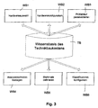
- the configuration tool PW includes a technology kit TB with knowledge bases WB1..WB3.
- On the Diagnostic system DS and the project planning tool WB can be accessed by a user via user interfaces 6a, 6b be accessed from.
- test object 1 In order to obtain the desired assessment of test object 1, the components of the diagnostic system must make sense parameterized and coordinated. Both The systems currently available on the market are Systems developed by the experts from the respective divisions be developed and put together. This brings you high project planning effort. This must be for every new one DUT types are operated again. In each of Standard methods are used that follow the steps the respective test task can be adapted. The adjustment is made based on expert knowledge. This required knowledge from the individual areas it almost makes a single person impossible to configure a complete test system yourself. From this arises the demand for the development of a universal test system that uses a knowledge base about the technology of the object to be inspected and the relevant one Measurement and evaluation methodology for the user during project planning supports and thus reduces the configuration effort.
- the diagnostic system DS shown in FIGS. 1 and 2 on the other hand, the most varied can be easily accessed Test tasks in vibroacoustic diagnosis can be adapted can. Furthermore, the user is during the Project planning and parameterization phase of the system in the form supported by suggestions and led in the logical sequence. To do this, it is necessary to generalize the system usable core and in industry-specific additions divide. An industry-specific addition is called Technology kit called TB, the Configuration tool can be added.
- the Core system is also without the support of one Technology kit TB configurable, but by the user A high level of knowledge of the procedures used is expected.
- Fig. 3 shows a schematic representation of exemplary Areas of responsibility of knowledge bases WB1..WB6 TB technology kit.
- a technology kit contains knowledge bases WB1..WB6, the information about the technology of the test object, the associated vibroacoustic properties, the metrological relationships and the Signal processing methodology included. The information and the rules that can be derived from it support the user like is shown in Fig. 3 in the configuration of the system.
- test equipment is about the operator for his Suitable sensors and the matching test task Acquisition hardware from a well-known hardware catalog propose.
- An additional point is support when configuring the selected hardware components, e.g. at which position a sensor with which method is to be attached.
- test conditions under which the test object is to be recorded assistance by means of a modular system is also required.
- These are not only test conditions that directly affect the test object, but also indirect ones.
- An example of a direct test condition is the type of excitation of a ceramic test object.
- An indirect one can be a maximum permissible ambient sound level.
- Another focus of the project planner to be supported is the selection of appropriate signal processing methods. This starts with the selection and parameterization of an analysis method with which the signals obtained are to be processed. The interpretation of the analysis result from a technological point of view also requires the knowledge of the engineering kit. Based on these interpretations and the technological knowledge of the modular system, meaningful characteristics can then be defined by the user. Similar to the analysis method, it is also possible to consult the knowledge of the technology kit about the methodology in the classification.
- the Technology kit in advance of the actual project planning Information about the test object can be provided. This receives the modular technology from the user by targeting the operator according to the relevant properties of the Test object.
- the TB technology kit consists of a class K and subclasses UK1, UK2, each again from hierarchically subordinate others Subclasses UK11, UK12 can be constructed.
- Class K includes Knowledge in the form of rules and functions that these rules apply and interpret. With this class structure parallels to the structure of the object-oriented Pull programming. Each subclass UK specifies that Knowledge and functionality of your parent class more accurate. So an upper class “rotating machines” (e.g. Information about speed) by a subclass “Electric motors” (e.g. information about the number of poles etc.) concretized. Such classes can be broken down by others Subclasses even more specific (e.g. additional Class "Asynchronous Motors").
- FIG. 5 shows the structure of the compiled Technology kit drive unit TB.
- a technology kit TB drive unit from the shares of Technology kits, TBM motors, TBL bearings and TBG gearboxes put together plus specific knowledge TBs about that Behavior of a drive unit and additional required Functionality.
- the first step is to get an overview of the variety of products in the industry for which the modular technology is to be developed.
- the rough frame is already staked out, which product areas the modular technology will cover.
- the next step involves structuring the branch into the individual subclasses, which, based on the previous considerations, have similar technological properties and thus also a similar vibration and noise behavior.
- an attempt is made to describe the type of test object using its technological data in terms of its vibration behavior.
- the measurement data obtained are now the various Subjected to analytical procedures to make statements about it can be, which procedures with which parameters are best suited for this type of test object. It will also examines how a vibration phenomenon in the Analysis result expresses and what technological occurrence underlying. It is also determined which Vibration phenomena are specific to this test object and which have a general character. Just knowledge that can be transferred to other types of test objects be added to the knowledge base. This knowledge serves later the user when interpreting his Support measurement results. An aid to the Characteristic definition can only take place if there is also here general characteristics for certain error classes get diagnosed.
- FIG. 6 shows an exemplary representation of a Characteristic evaluation for 18 characteristics and 59 motors as Test objects.
- the distinctness of the engines in the each class uses a characteristic to describe it Quality.
- To get an overall impression of the effectiveness of Getting characteristics was the 18 characteristics for each engine shown in Fig. 6 as a false color plot. Every feature line was normalized to its maximum value.
- the value of a characteristic is coded in color (the color scale changes from blue (0) green / yellow (0.5) to red / brown (1)).
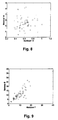
- FIG. 7 shows the features 2 (housing radial 3fL-5fL) and 17 (Bearing B plain bearing vibrations). As you can see, deliver the two characteristics do not differentiate the motors well. This could also be seen in FIG. 6. A better The two features 10 separate the motors (Bearing A lamellar frequency) and 16 (bearing B 5fL-9fL) ( Figure 4-18). Here, by choosing one Threshold values for each characteristic, approx. 40 of the 54 faulty ones Motors are separated. This is also shown in Fig. 6, where for features 10 and 16 of the first five engines uniform color tone prevails, but color tones higher Intensity in the bad.
- the separability would have a cluster of good engines in the scatterplot with two characteristics, which does not intersect with those of the other error classes. However, several characteristics are probably always required so that all motors can be classified correctly.
- Figure 9 shows features 7 and 8. It is interesting here that the points are arranged on a diagonal. This structure indicates that the two characteristics are statistically dependent on each other and therefore say the same thing.
- the invention relates to an acoustic Diagnostic system D for automatic in particular Quality control of test objects 1, especially of Motors, of ceramics etc., with a sensor system 2, in particular sound sensors, for converting mechanical Vibrations in electrical signals E, with a Signal conditioning 3a, 3b for amplification and Low pass filtering of the electrical signals E, with a Analog / digital converter 3c to convert the amplified and low pass filtered signals in discrete digital values and with a signal processing unit 4 for signal analysis, Feature extraction and classification of each Test object 1 to be assigned errors and / or quality class, where the system means for automatic archiving via the Occurrence and frequency of quality and / or defect classes having.
- the diagnostic system can include control means to control a production process for manufacturing of the test object 1 are provided.
Landscapes
- Physics & Mathematics (AREA)
- General Physics & Mathematics (AREA)
- Chemical & Material Sciences (AREA)
- General Health & Medical Sciences (AREA)
- Life Sciences & Earth Sciences (AREA)
- Health & Medical Sciences (AREA)
- Analytical Chemistry (AREA)
- Biochemistry (AREA)
- Engineering & Computer Science (AREA)
- Immunology (AREA)
- Pathology (AREA)
- Acoustics & Sound (AREA)
- Signal Processing (AREA)
- Combustion & Propulsion (AREA)
- Testing Of Devices, Machine Parts, Or Other Structures Thereof (AREA)
- Measurement Of Mechanical Vibrations Or Ultrasonic Waves (AREA)
Claims (12)
- Système de diagnostic acoustique (D) pour le contrôle de qualité notamment automatique d'objets d'essai (1), notamment de moteurs, de céramiques, etc., comprenant une unité sensorielle (2), notamment des capteurs acoustiques, pour la transformation d'oscillations mécaniques en signaux électriques (E), un conditionnement de signal (3a, 3b) pour l'amplification et le filtrage passe-bas des signaux électriques (E), un convertisseur analogique-numérique (3c) pour la conversion des signaux amplifiés et filtrés passe-bas en valeurs numériques discrètes et avec une unité de traitement de signal (4) pour l'analyse de signal, pour l'extraction de caractéristiques et pour la classification d'une classe de défaut et/ou de qualité à associer à un objet à contrôler (1) respectif, le système comportant des moyens pour l'archivage automatique de l'occurrence et de la fréquence de classes de qualité et/ou de défaut et le système comprenant des moyens pour la détermination de caractéristiques redondantes par une corrélation de caractéristiques existantes.
- Système de diagnostic selon la revendication 1, dans lequel le système de diagnostic (D) comporte des moyens de commande ou est couplé à des moyens de commande qui sont prévus pour la commande d'un processus de production en vue de la fabrication de l'objet à contrôler (1).
- Système de diagnostic selon l'une des revendications 1 ou 2, dans lequel le système de diagnostic (D) comprend des moyens qui déterminent plusieurs classifications à l'aide d'un signal d'entrée (E) d'un objet à contrôler (1).
- Système de diagnostic selon la revendication 3, dans lequel le système de diagnostic comprend des moyens qui déterminent à l'aide d'un signal d'entrée (E) associé à un objet à contrôler plusieurs caractéristiques pour la classification de l'objet à contrôler (E), les valeurs de caractéristiques associées aux caractéristiques respectives étant codées à chaque fois par des couleurs.
- Système de diagnostic selon l'une des revendications 1 à 4, dans lequel le système de diagnostic (D) comporte des moyens (4, 5) pour la production d'une matrice de corrélation afin de visualiser les caractéristiques redondantes.
- Système de diagnostic selon l'une des revendications 1 à 5, dans lequel le système de diagnostic (D) est prévu pour le contrôle de qualité d'objets d'essai (1) auto-excités, notamment de moteurs, et/ou d'objets d'essai (1) excités de l'extérieur, notamment de verre ou de céramique.
- Procédé pour le contrôle de qualité notamment automatique d'objets d'essai (1), notamment de moteurs, de céramiques, etc., dans lequel des oscillations mécaniques sont transformées en signaux électriques (E) avec une unité sensorielle (2), notamment avec des capteurs acoustiques, dans lequel les signaux électriques (E) sont amplifiés et filtrés passe-bas avec un conditionnement de signal (3a, 3b), dans lequel les signaux amplifiés et filtrés passe-bas sont convertis en valeurs numériques discrètes avec un convertisseur analogique-numérique (3c) et dans lequel on effectue dans une unité de traitement de signal (4) une analyse de signal, une extraction de caractéristiques et une classification de la classe de défaut et/ou de qualité à associer à un objet à contrôler (1) respectif, l'occurrence et la fréquence de classes de qualité et/ou de défaut étant archivées automatiquement et des caractéristiques redondantes étant déterminées par une corrélation de caractéristiques existantes.
- Procédé selon la revendication 7, dans lequel on commande via le procédé de diagnostic un processus de production pour la fabrication de l'objet à contrôler (1).
- Procédé selon l'une des revendications 7 ou 8, dans lequel on détermine plusieurs classifications à l'aide d'un signal d'entrée (E) d'un objet à contrôler (1).
- Procédé selon la revendication 9, dans lequel on détermine à l'aide d'un signal d'entrée (E) associé à un objet à contrôler plusieurs caractéristiques pour la classification de l'objet à contrôler (1), les valeurs de caractéristiques associées aux caractéristiques respectives étant codées à chaque fois par des couleurs.
- Procédé selon l'une des revendications 7 à 10, dans lequel on visualise les caractéristiques redondantes en produisant une matrice de corrélation.
- Procédé selon l'une des revendications 7 à 11, dans lequel on utilisa le procédé de diagnostic pour le contrôle de qualité d'objets d'essai (1) auto-excités, notamment de moteurs, et/ou d'objets d'essai (1) excités de l'extérieur, notamment de verre ou de céramique.
Applications Claiming Priority (3)
| Application Number | Priority Date | Filing Date | Title |
|---|---|---|---|
| DE19817169 | 1998-04-17 | ||
| DE19817169 | 1998-04-17 | ||
| PCT/DE1999/001118 WO1999054703A2 (fr) | 1998-04-17 | 1999-04-14 | Systeme et procede de diagnostic acoustique |
Publications (2)
| Publication Number | Publication Date |
|---|---|
| EP1088211A2 EP1088211A2 (fr) | 2001-04-04 |
| EP1088211B1 true EP1088211B1 (fr) | 2003-06-25 |
Family
ID=7864909
Family Applications (1)
| Application Number | Title | Priority Date | Filing Date |
|---|---|---|---|
| EP99926241A Expired - Lifetime EP1088211B1 (fr) | 1998-04-17 | 1999-04-14 | Systeme et procede de diagnostic acoustique |
Country Status (5)
| Country | Link |
|---|---|
| US (1) | US6591226B1 (fr) |
| EP (1) | EP1088211B1 (fr) |
| DE (1) | DE59906108D1 (fr) |
| DK (1) | DK1088211T3 (fr) |
| WO (1) | WO1999054703A2 (fr) |
Cited By (3)
| Publication number | Priority date | Publication date | Assignee | Title |
|---|---|---|---|---|
| WO2004097364A1 (fr) * | 2003-04-30 | 2004-11-11 | Thomas Jaggo | Procede et dispositif de verification du fonctionnement d'objets a controler |
| DE102005023256A1 (de) * | 2005-05-20 | 2006-11-23 | Deere & Company, Moline | Überwachungseinrichtung und ein Verfahren zur Überwachung der Funktion der Komponenten einer landwirtschaftlichen Arbeitsmaschine |
| DE102011083568A1 (de) * | 2011-09-28 | 2013-03-28 | BSH Bosch und Siemens Hausgeräte GmbH | Verfahren zum Identifizieren einer Eigenschaft einer periodisch schwingenden Einheit |
Families Citing this family (25)
| Publication number | Priority date | Publication date | Assignee | Title |
|---|---|---|---|---|
| ES2168962B1 (es) * | 2000-05-16 | 2003-11-16 | Pascual Vicente Segui | Maquina para el control automatico de calidad de productos ceramicos por vision artificial y analisis de sonido. |
| US20040236450A1 (en) * | 2000-09-25 | 2004-11-25 | Motorwiz, Inc. | Model-based machine diagnostics and prognostics using theory of noise and communications |
| US6847917B2 (en) | 2001-05-24 | 2005-01-25 | Simmonds Precision Products, Inc. | Method and apparatus for selecting condition indicators in determining the health of a component |
| US6728658B1 (en) | 2001-05-24 | 2004-04-27 | Simmonds Precision Products, Inc. | Method and apparatus for determining the health of a component using condition indicators |
| US6711523B2 (en) | 2001-05-24 | 2004-03-23 | Simmonds Precision Products, Inc. | Method and apparatus for determining a condition indicator for use in evaluating the health of a component |
| US6651012B1 (en) | 2001-05-24 | 2003-11-18 | Simmonds Precision Products, Inc. | Method and apparatus for trending and predicting the health of a component |
| CA2439734A1 (fr) * | 2001-05-24 | 2002-11-28 | Simmonds Precision Products, Inc. | Methodes et dispositif permettant de determiner la condition d'un composant au moyen d'indicateurs d'etat |
| US7136794B1 (en) | 2001-05-24 | 2006-11-14 | Simmonds Precision Products, Inc. | Method and apparatus for estimating values for condition indicators |
| US6754569B2 (en) | 2001-05-24 | 2004-06-22 | Simmonds Precision Products, Inc. | Method and apparatus for normalizing condition indicators |
| DE10244650A1 (de) * | 2002-09-25 | 2004-04-08 | Siemens Ag | Kalibriersystem, insbesondere für ein Schwingungsmesssystem |
| US7627441B2 (en) | 2003-09-30 | 2009-12-01 | Rosemount Inc. | Process device with vibration based diagnostics |
| DE102004023824B4 (de) * | 2004-05-13 | 2006-07-13 | Fraunhofer-Gesellschaft zur Förderung der angewandten Forschung e.V. | Vorrichtung und Verfahren zur Beurteilung einer Güteklasse eines zu prüfenden Objekts |
| FR2900745B1 (fr) * | 2006-05-05 | 2008-10-10 | Eurocopter France | Procede et dispositif de diagnostic d'un mecanisme |
| DE102007027502A1 (de) * | 2007-06-14 | 2008-12-18 | Bayerische Motoren Werke Aktiengesellschaft | Verfahren zur audiologischen Prüfung |
| US7991580B2 (en) * | 2008-04-16 | 2011-08-02 | Honeywell International Inc. | Benchmarking diagnostic algorithms |
| DE102008021362B3 (de) * | 2008-04-29 | 2009-07-02 | Siemens Aktiengesellschaft | Verfahren und Vorrichtung zum Erkennen eines Zustandes einer zu untersuchenden geräuscherzeugenden Maschine |
| DE102008022125A1 (de) | 2008-05-05 | 2009-11-19 | Siemens Aktiengesellschaft | Verfahren und Vorrichtung zur Klassifikation von schallerzeugenden Prozessen |
| DE102011114058B4 (de) * | 2011-09-22 | 2022-02-17 | Volkswagen Aktiengesellschaft | Verfahren und Vorrichtung zur akustischen Beurteilung eines Bauteils |
| CN104854449B (zh) * | 2011-10-27 | 2017-09-08 | Msi蒂法特公司 | 用于直接场声学测试的驱动信号分配 |
| WO2014062729A1 (fr) * | 2012-10-15 | 2014-04-24 | Msi Dfat Llc | Essai acoustique à champ direct dans une chambre semi-réverbérante |
| US9835594B2 (en) | 2012-10-22 | 2017-12-05 | Augury Systems Ltd. | Automatic mechanical system diagnosis |
| FR3098589B1 (fr) * | 2019-07-09 | 2021-07-30 | Somfy Activites Sa | Banc de contrôle d’un actionneur électromécanique pour une installation de fermeture, d’occultation ou de protection solaire |
| JP7834571B2 (ja) * | 2022-05-02 | 2026-03-24 | 株式会社ミツバ | モータ装置の検査装置およびモータ装置の検査方法 |
| FR3142548A1 (fr) * | 2022-11-24 | 2024-05-31 | Psa Automobiles Sa | Vehicule automobile comprenant un systeme de diagnostic de bruits et vibrations anormaux, procede et programme sur la base d’un tel vehicule |
| DE102022132935A1 (de) * | 2022-12-12 | 2024-06-13 | KyooBe Tech GmbH | Produktionsanlage zur Herstellung eines Produkts |
Family Cites Families (20)
| Publication number | Priority date | Publication date | Assignee | Title |
|---|---|---|---|---|
| JPH0692914B2 (ja) * | 1989-04-14 | 1994-11-16 | 株式会社日立製作所 | 機器/設備の状態診断システム |
| JP2997571B2 (ja) * | 1991-07-10 | 2000-01-11 | 三菱電機株式会社 | 監視診断装置 |
| DE4207728A1 (de) * | 1992-03-11 | 1993-09-23 | Fraunhofer Ges Forschung | Verfahren zur qualitaetspruefung von pruefobjekten |
| FR2692037B1 (fr) * | 1992-06-03 | 1997-08-08 | Thomson Csf | Procede de diagnostic d'un processus evolutif. |
| US5511422A (en) * | 1993-04-09 | 1996-04-30 | Monitoring Technology Corporation | Method and apparatus for analyzing and detecting faults in bearings and other rotating components that slip |
| US5566092A (en) * | 1993-12-30 | 1996-10-15 | Caterpillar Inc. | Machine fault diagnostics system and method |
| US5602761A (en) * | 1993-12-30 | 1997-02-11 | Caterpillar Inc. | Machine performance monitoring and fault classification using an exponentially weighted moving average scheme |
| US5602757A (en) * | 1994-10-20 | 1997-02-11 | Ingersoll-Rand Company | Vibration monitoring system |
| US5710723A (en) * | 1995-04-05 | 1998-01-20 | Dayton T. Brown | Method and apparatus for performing pre-emptive maintenance on operating equipment |
| US5761090A (en) * | 1995-10-10 | 1998-06-02 | The University Of Chicago | Expert system for testing industrial processes and determining sensor status |
| US5943634A (en) * | 1996-05-14 | 1999-08-24 | Csi Technology, Inc. | Vibration data analysis based on time waveform parameters |
| DE29611558U1 (de) | 1996-07-05 | 1997-08-07 | Siemens AG, 80333 München | Vorrichtung zur Erfassung von analogen Meßsignalen für die akustische Diagnose von Prüflingen |
| US5963884A (en) * | 1996-09-23 | 1999-10-05 | Machine Xpert, Llc | Predictive maintenance system |
| US6041287A (en) * | 1996-11-07 | 2000-03-21 | Reliance Electric Industrial Company | System architecture for on-line machine diagnostics |
| US5852793A (en) * | 1997-02-18 | 1998-12-22 | Dme Corporation | Method and apparatus for predictive diagnosis of moving machine parts |
| JP3366837B2 (ja) * | 1997-08-15 | 2003-01-14 | 株式会社小松製作所 | 機械の異常監視装置および方法 |
| US5995910A (en) * | 1997-08-29 | 1999-11-30 | Reliance Electric Industrial Company | Method and system for synthesizing vibration data |
| US6199018B1 (en) * | 1998-03-04 | 2001-03-06 | Emerson Electric Co. | Distributed diagnostic system |
| US5991707A (en) * | 1998-03-09 | 1999-11-23 | Hydrotec Systems Company, Inc. | Method and system for predictive diagnosing of system reliability problems and/or system failure in a physical system |
| US6192325B1 (en) * | 1998-09-15 | 2001-02-20 | Csi Technology, Inc. | Method and apparatus for establishing a predictive maintenance database |
-
1999
- 1999-04-14 EP EP99926241A patent/EP1088211B1/fr not_active Expired - Lifetime
- 1999-04-14 DK DK99926241T patent/DK1088211T3/da active
- 1999-04-14 DE DE59906108T patent/DE59906108D1/de not_active Expired - Fee Related
- 1999-04-14 WO PCT/DE1999/001118 patent/WO1999054703A2/fr not_active Ceased
-
2000
- 2000-10-17 US US09/688,801 patent/US6591226B1/en not_active Expired - Fee Related
Cited By (3)
| Publication number | Priority date | Publication date | Assignee | Title |
|---|---|---|---|---|
| WO2004097364A1 (fr) * | 2003-04-30 | 2004-11-11 | Thomas Jaggo | Procede et dispositif de verification du fonctionnement d'objets a controler |
| DE102005023256A1 (de) * | 2005-05-20 | 2006-11-23 | Deere & Company, Moline | Überwachungseinrichtung und ein Verfahren zur Überwachung der Funktion der Komponenten einer landwirtschaftlichen Arbeitsmaschine |
| DE102011083568A1 (de) * | 2011-09-28 | 2013-03-28 | BSH Bosch und Siemens Hausgeräte GmbH | Verfahren zum Identifizieren einer Eigenschaft einer periodisch schwingenden Einheit |
Also Published As
| Publication number | Publication date |
|---|---|
| US6591226B1 (en) | 2003-07-08 |
| WO1999054703A2 (fr) | 1999-10-28 |
| DE59906108D1 (de) | 2003-07-31 |
| DK1088211T3 (da) | 2003-10-20 |
| EP1088211A2 (fr) | 2001-04-04 |
| WO1999054703A3 (fr) | 1999-12-23 |
Similar Documents
| Publication | Publication Date | Title |
|---|---|---|
| EP1088211B1 (fr) | Systeme et procede de diagnostic acoustique | |
| EP1071937B1 (fr) | Systeme et procede pour configurer et/ou parametrer une unite de diagnostic | |
| DE102018103232B4 (de) | Fehlerdiagnosesystem | |
| DE60010655T2 (de) | Verfahren und vorrichtung in einem fahrzeugüberwachungssystem und fehlerdiagnosesystem in einem fahrzeug | |
| EP0789861B1 (fr) | Procede d'analyse des donnees d'operations d'une installation technique | |
| DE102016013406B4 (de) | Verfahren zum Betrieb eines Zustandsüberwachungssystems einer Schwingmaschine und Zustandsüberwachungssystem | |
| DE102017124135A1 (de) | Maschinenfehlervorhersage basierend auf einer Analyse von periodischen Informationen in einem Signal | |
| DE19545008A1 (de) | Verfahren und Vorrichtung zur Überwachung von Maschinen | |
| WO2008003575A2 (fr) | Instrument de mesure avec surveillance d'état et procédé de surveillance de l'état d'un instrument de mesure | |
| DE102008029087A1 (de) | Überwachungssystem für ein Schwingungen unterworfenes Aggregat | |
| DE3877912T2 (de) | Verfahren zur ueberwachung von schallemissionen. | |
| DE69517075T2 (de) | Gerät zur Diagnose von Schall- und Schwingungsquellen | |
| DE4406723A1 (de) | Verfahren zur Überwachung des Betriebszustands einer Maschine oder Anlage | |
| DE102021102712A1 (de) | Verfahren und System zur akustischen Diagnose eines Kraftfahrzeugs anhand von Betriebsgeräuschen | |
| DE102011114058A1 (de) | Verfahren und Vorrichtung zu akustischen Beurteilung eines Bauteils | |
| DE102014212733A1 (de) | Auditive Prüfung von Geräuschen | |
| DE69008192T2 (de) | Verfahren und vorrichtung zur speicherung intermittierender funktioneller fehler eines physikalischen systems und von kontextvariablen dieser fehler. | |
| DE102022105157A1 (de) | Zustandsdiagnosesystem | |
| DE102021212524A1 (de) | Verfahren zum Betreiben eines Sensors | |
| DE19855874A1 (de) | System und Verfahren zur Projektierung und Durchführung von Prüfabläufen | |
| EP3921810B1 (fr) | Procédé et dispositif d'identification automatisée d'un défaut d'un produit et/ou d'identification automatisée d'une cause du défaut du produit | |
| DE19800217A1 (de) | Verfahren zur automatisierten Diagnose von Diagnoseobjekten | |
| DE102023005489B4 (de) | Virtual- Reality-unterstütztes Diagnoseverfahren für eine Anlage mit computerbasierter Auralisierung | |
| DE102023205572B3 (de) | Virtual-Reality-unterstütztes Diagnoseverfahren für eine Anlage mit computerbasierter Auralisierung | |
| EP1246034B1 (fr) | Procédé pour l'analyse et l'estimation de valeurs de mesure d'un système d'essai |
Legal Events
| Date | Code | Title | Description |
|---|---|---|---|
| PUAI | Public reference made under article 153(3) epc to a published international application that has entered the european phase |
Free format text: ORIGINAL CODE: 0009012 |
|
| 17P | Request for examination filed |
Effective date: 20001009 |
|
| AK | Designated contracting states |
Kind code of ref document: A2 Designated state(s): DE DK FR GB IT |
|
| 17Q | First examination report despatched |
Effective date: 20020425 |
|
| GRAH | Despatch of communication of intention to grant a patent |
Free format text: ORIGINAL CODE: EPIDOS IGRA |
|
| GRAH | Despatch of communication of intention to grant a patent |
Free format text: ORIGINAL CODE: EPIDOS IGRA |
|
| GRAA | (expected) grant |
Free format text: ORIGINAL CODE: 0009210 |
|
| AK | Designated contracting states |
Designated state(s): DE DK FR GB IT |
|
| REG | Reference to a national code |
Ref country code: GB Ref legal event code: FG4D Free format text: NOT ENGLISH |
|
| GBT | Gb: translation of ep patent filed (gb section 77(6)(a)/1977) | ||
| REF | Corresponds to: |
Ref document number: 59906108 Country of ref document: DE Date of ref document: 20030731 Kind code of ref document: P |
|
| PLBE | No opposition filed within time limit |
Free format text: ORIGINAL CODE: 0009261 |
|
| STAA | Information on the status of an ep patent application or granted ep patent |
Free format text: STATUS: NO OPPOSITION FILED WITHIN TIME LIMIT |
|
| ET | Fr: translation filed | ||
| 26N | No opposition filed |
Effective date: 20040326 |
|
| PGFP | Annual fee paid to national office [announced via postgrant information from national office to epo] |
Ref country code: DK Payment date: 20070410 Year of fee payment: 9 |
|
| PGFP | Annual fee paid to national office [announced via postgrant information from national office to epo] |
Ref country code: IT Payment date: 20070607 Year of fee payment: 9 |
|
| PGFP | Annual fee paid to national office [announced via postgrant information from national office to epo] |
Ref country code: DE Payment date: 20080620 Year of fee payment: 10 |
|
| REG | Reference to a national code |
Ref country code: DK Ref legal event code: EBP |
|
| PG25 | Lapsed in a contracting state [announced via postgrant information from national office to epo] |
Ref country code: DK Free format text: LAPSE BECAUSE OF NON-PAYMENT OF DUE FEES Effective date: 20080430 |
|
| PG25 | Lapsed in a contracting state [announced via postgrant information from national office to epo] |
Ref country code: IT Free format text: LAPSE BECAUSE OF NON-PAYMENT OF DUE FEES Effective date: 20080414 |
|
| PGFP | Annual fee paid to national office [announced via postgrant information from national office to epo] |
Ref country code: FR Payment date: 20090424 Year of fee payment: 11 |
|
| PGFP | Annual fee paid to national office [announced via postgrant information from national office to epo] |
Ref country code: GB Payment date: 20090409 Year of fee payment: 11 |
|
| PG25 | Lapsed in a contracting state [announced via postgrant information from national office to epo] |
Ref country code: DE Free format text: LAPSE BECAUSE OF NON-PAYMENT OF DUE FEES Effective date: 20091103 |
|
| GBPC | Gb: european patent ceased through non-payment of renewal fee |
Effective date: 20100414 |
|
| REG | Reference to a national code |
Ref country code: FR Ref legal event code: ST Effective date: 20101230 |
|
| PG25 | Lapsed in a contracting state [announced via postgrant information from national office to epo] |
Ref country code: GB Free format text: LAPSE BECAUSE OF NON-PAYMENT OF DUE FEES Effective date: 20100414 |
|
| PG25 | Lapsed in a contracting state [announced via postgrant information from national office to epo] |
Ref country code: FR Free format text: LAPSE BECAUSE OF NON-PAYMENT OF DUE FEES Effective date: 20100430 |