EP1088962A2 - Appareil de flottation pour l'utilisation dans un tubage de puits - Google Patents
Appareil de flottation pour l'utilisation dans un tubage de puits Download PDFInfo
- Publication number
- EP1088962A2 EP1088962A2 EP01200033A EP01200033A EP1088962A2 EP 1088962 A2 EP1088962 A2 EP 1088962A2 EP 01200033 A EP01200033 A EP 01200033A EP 01200033 A EP01200033 A EP 01200033A EP 1088962 A2 EP1088962 A2 EP 1088962A2
- Authority
- EP
- European Patent Office
- Prior art keywords
- valve
- sleeve
- outer case
- body portion
- annulus
- Prior art date
- Legal status (The legal status is an assumption and is not a legal conclusion. Google has not performed a legal analysis and makes no representation as to the accuracy of the status listed.)
- Granted
Links
Images

Classifications
-
- E—FIXED CONSTRUCTIONS
- E21—EARTH OR ROCK DRILLING; MINING
- E21B—EARTH OR ROCK DRILLING; OBTAINING OIL, GAS, WATER, SOLUBLE OR MELTABLE MATERIALS OR A SLURRY OF MINERALS FROM WELLS
- E21B34/00—Valve arrangements for boreholes or wells
- E21B34/06—Valve arrangements for boreholes or wells in wells
-
- E—FIXED CONSTRUCTIONS
- E21—EARTH OR ROCK DRILLING; MINING
- E21B—EARTH OR ROCK DRILLING; OBTAINING OIL, GAS, WATER, SOLUBLE OR MELTABLE MATERIALS OR A SLURRY OF MINERALS FROM WELLS
- E21B21/00—Methods or apparatus for flushing boreholes, e.g. by use of exhaust air from motor
- E21B21/10—Valve arrangements in drilling-fluid circulation systems
Definitions
- This invention relates to floating apparatus used in well cementing operations and to a method of making such apparatus.
- casing will be lowered into and cemented therein.
- the weight of the casing particularly with deep wells, creates a tremendous amount of stress and strain on equipment used to lower the casing into the well.
- floating equipment such as for example float collars and/or float shoes, is used in the casing string.
- the float equipment typically consists of a valve fixed to the outer case which allows fluid to flow down through the casing but prevents flow in the opposite direction. Because upward flow is obstructed, a portion of the weight of the casing will float or ride on the well fluid thus reducing the amount of weight carried by the equipment lowering the casing into the well.
- cement is flowed down through the inner diameter of the casing, through the valve and into the annular space between the outer diameter of the casing and the well bore.
- the valve keeps the cement below and behind the casing string.
- US-A-5,379,835 describes insertion type floating equipment which may be retained in the casing through the use of slips or set screws. Downhole floating apparatus is, however, usually fabricated by fixing a check valve in an outer case which is adapted to be threaded directly into a casing string.
- US-A-5,472,053 describes a floating apparatus with an outer sleeve adapted to be connected to a casing string. The valve is fixed by filling the annulus between the valve housing and the outer case with a high compressive strength cement to form a cement body portion. The cement body portion transfers the valve load to the outer case such that the valve remains securely fixed within the outer case as pressure is being applied thereto.
- the present invention provides improved means for fixing the valve in the floating apparatus, and thus provides an effective and more economically produced floating apparatus.
- a floating apparatus in the form of a float shoe for use in a well casing, the apparatus comprising an outer case adapted to be connected to the well casing; a sleeve having an outer surface and an inner surface, a valve disposed in said sleeve, said valve including a valve housing having a central opening; and a first body portion fixedly attached to said valve housing and to said inner surface, wherein said first body portion fills an annulus defined between said inner surface of said sleeve and said valve housing; and a second body portion fixedly attached to said sleeve and said outer case, said second body portion being located in an annulus defined between said sleeve and said outer case.
- the valve includes a check valve comprising a valve seat defined on said valve housing; a valve guide disposed in the central opening of said valve housing; a valve element having a sealing surface sealingly engageable with said valve seat; and a valve stem extending upwardly from said valve element and slidably received through said valve guide.
- the apparatus further comprises means for releasably disengaging said valve element from said valve seat, so that fluid can pass through the central opening as the casing is lowered into a well and so that said valve element and said valve seat can be sealingly engaged after the casing has been lowered into the well.
- a method of making floating apparatus in the form of a float shoe for use in a well casing comprises the steps of: positioning a valve within a sleeve, said valve having a valve housing wherein an annulus is defined between an inner surface of said sleeve and said valve housing; filling said annulus between said sleeve and said valve housing with cement to form a first cement body portion for fixing said valve housing to said sleeve; and providing a second cement body portion for affixing said sleeve to said outer case, said second cement body portion being located in an annulus defined between said sleeve and said outer case.
- the floating apparatus of the present invention is designed to provide improved means for transferring valve load to an outer case.
- the outer case is individually coupled to a lower casing string section.
- the lower casing string section has an inner surface which defines a central flow passage.
- a check valve is disposed in a sleeve which is receivable in the outer case.
- the valve includes a valve housing with an outer surface and an inner surface, wherein the inner surface may be referred to as a central opening communicated with the central flow passage.
- a first body portion is fixedly attached to the valve housing and sleeve, thereby holding the valve within the sleeve.
- the first body portion fills the annulus between the sleeve and valve housing, and may be comprised of high compressive strength cement.
- a second body portion is fixedly attached to the sleeve and outer case, thereby holding the sleeve to an affixed valve therein.
- the second body portion partially fills the annulus between the sleeve and the outer case, and may be comprised of high compressive strength cement.
- the outer case of the float shoe of the present invention is shorter, and thus, more economical to produce than that currently used in conventional float shoes.
- the invention also includes a method of fabricating floating apparatus having improved means for transferring valve load to an outer case.
- the method includes radially centrally positioning a valve in a sleeve, wherein the valve has a valve housing and an annulus is defined between an inner surface of the sleeve and the housing.
- the method further includes filling the annulus between the sleeve and valve housing with cement to form a first cement body portion, thereby affixing the valve housing to the sleeve.
- the method further includes radially centrally positioning the sleeve to the outer case, which is threaded to receive the lower casing string section.
- An annulus is defined between an inner surface of the outer case and the sleeve.
- the annulus located between the sleeve and the outer case is partially filled with cement to form a second cement body portion, thereby affixing the sleeve to the outer case. Further, the casing is received in the annulus when the casing is threadably coupled with the outer case.
- An intention of the present invention is to provide an improved method of fabricating floating apparatus for cementing casing string in a well bore.
- the present invention may provide floating apparatus having improved means of transferring valve load between a valve and outer case.
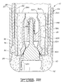
- a check valve 30 is centrally disposed in a sleeve 32.
- the sleeve 32 has an inner surface 34 and outer surface 36.
- the sleeve 32 is constructed of a drillable material such as aluminium or non-metallic materials including engineering grade plastics, resins, composites, or other suitably known materials.
- the valve 30 includes a valve housing 44 having an upper end 46, a lower end 48, an outer surface 50 and an inner surface 52.
- the inner surface 52 may also be referred to as a central opening 52.
- An annulus 54 is defined between the valve housing 44 and inner surface 34 of the sleeve 32.
- a valve seat 56 is defined on the inner surface 52 of the housing 44.
- the check valve 30 further includes a valve element 58 having a sealing surface 60 which sealingly engages the valve seat 56.
- a lip seal 62 may be defined on the sealing surface 60.
- a valve guide 64 disposed in the valve housing 44 slidingly receives a valve stem 66 which extends upwardly from the valve element 58.
- a valve cap 68 is attached to an upper end 70 of the valve stem 66.
- a valve spring 72 is disposed about the valve stem 66 between the valve cap 68 and the valve guide 64. The valve spring 72 biases the valve cap 68 upwardly thereby sealingly engaging the valve seat 56 and sealing surface 60 of the valve element 58.
- the valve 30 may further include an auto-fill strap 74 attached to the valve element 58.
- the auto-fill strap 74 has a rounded end or bead 76 disposed at each end.
- the beads 76 may be placed between the valve seat 56 and sealing surface 60 prior to lowering the casing string into a well, thereby allowing fluid to flow through the casing and through the apparatus 10 as it is lowered into the well.
- the auto-fill strap 74 may be referred to as a means for releasably disengaging the valve element 58 from the valve seat 56.
- the apparatus 10 further includes a first body portion 78 disposed in the annulus 54 defined between the valve housing 44 and inner surface 34 of the sleeve 32.
- the body portion 78 is typically comprised of a high compressive strength cement which fixedly attaches the valve housing 44 to the inner surface 34 of the sleeve 32.
- the sleeve 32 is disposed in the outer case 80 and an annulus 94 is defined therebetween.
- the float shoe is generally designated by the numeral 12A and has an outer case 80 with an upper end 82 and a lower end 84.
- the upper end 82 is threaded 86 so that it may be threadably connected to a casing string 88 thereabove.
- the lower end 84 does not include a thread.
- the float shoe 12A includes an end portion 90 which extends below the lower end 84 of the outer case 80 and forms a guide surface 92.
- the float shoe 12A includes a second body portion 96 disposed in the annulus 94 defined between the sleeve 32 and outer case 80.
- the second body portion 96 is typically comprised of a high compressive strength cement which fixedly attaches an outer surface 36A of the sleeve 32A to an inner surface 98 of the outer case 80.
- the valve 30A should operate to keep cement from re-entering the casing 88.
- the preferred second body portion 96 only partially fills the annulus 94 between the sleeve 32A and outer case 80. Further, since the annulus 94 between the sleeve 32A and outer case 80 is only partially filled with cement, the casing string 88 is receivable between the sleeve 32A and outer case 80 for threadably coupling with the outer case 80.
- the casing string including the present invention is lowered into a well. Once the casing string is in place, the cement is flowed down and out the lower end of the casing string. The cement fills an annulus between the outer surface of the casing string and the well bore, thus cementing the casing in place.
- the invention also includes a method of fabricating floating apparatus, such as the float shoe, having improved means of transferring valve load to the outer case thereof.
- the method includes radially centrally positioning a valve, which has a valve housing, in a sleeve such that an annulus is defined between an outer surface of the valve housing and an inner surface of the sleeve. The sleeve is then positioned within the outer case.
- the method further includes filling the annulus between the sleeve and valve housing with cement to form a first cement body portion, thereby affixing the outer surface of the valve housing to the inner surface of the sleeve.
- the sleeve is radially centrally positioned in the outer case, wherein an annulus is defined between an inner surface of the outer case and the sleeve.
- the annulus defined between the sleeve and outer case is filled with cement to form a second cement body portion, thereby affixing the sleeve to the outer case.
- the apparatus and methods of the present invention provides a float shoe apparatus 10 which is effective and more economical to produce than conventional float equipment. Further, it will be seen that the floating apparatus 10 of the present invention and methods of fabricating such apparatus are well adapted to carry out the ends and advantages mentioned as well as those inherent therein.
Landscapes
- Engineering & Computer Science (AREA)
- Geology (AREA)
- Life Sciences & Earth Sciences (AREA)
- Mining & Mineral Resources (AREA)
- Environmental & Geological Engineering (AREA)
- Fluid Mechanics (AREA)
- Physics & Mathematics (AREA)
- General Life Sciences & Earth Sciences (AREA)
- Geochemistry & Mineralogy (AREA)
- Mechanical Engineering (AREA)
- Lift Valve (AREA)
- Check Valves (AREA)
- Float Valves (AREA)
- Valve Housings (AREA)
- Details Of Valves (AREA)
Applications Claiming Priority (3)
| Application Number | Priority Date | Filing Date | Title |
|---|---|---|---|
| US620056 | 1996-03-21 | ||
| US08/620,056 US5647434A (en) | 1996-03-21 | 1996-03-21 | Floating apparatus for well casing |
| EP97301796A EP0796979B1 (fr) | 1996-03-21 | 1997-03-18 | Appareil flottant pour usage souterrain et méthode pour sa mise en oeuvre |
Related Parent Applications (1)
| Application Number | Title | Priority Date | Filing Date |
|---|---|---|---|
| EP97301796A Division EP0796979B1 (fr) | 1996-03-21 | 1997-03-18 | Appareil flottant pour usage souterrain et méthode pour sa mise en oeuvre |
Publications (3)
| Publication Number | Publication Date |
|---|---|
| EP1088962A2 true EP1088962A2 (fr) | 2001-04-04 |
| EP1088962A3 EP1088962A3 (fr) | 2001-04-18 |
| EP1088962B1 EP1088962B1 (fr) | 2005-01-12 |
Family
ID=24484391
Family Applications (2)
| Application Number | Title | Priority Date | Filing Date |
|---|---|---|---|
| EP01200033A Expired - Lifetime EP1088962B1 (fr) | 1996-03-21 | 1997-03-18 | Appareil de flottation pour l'utilisation dans un tubage de puits |
| EP97301796A Expired - Lifetime EP0796979B1 (fr) | 1996-03-21 | 1997-03-18 | Appareil flottant pour usage souterrain et méthode pour sa mise en oeuvre |
Family Applications After (1)
| Application Number | Title | Priority Date | Filing Date |
|---|---|---|---|
| EP97301796A Expired - Lifetime EP0796979B1 (fr) | 1996-03-21 | 1997-03-18 | Appareil flottant pour usage souterrain et méthode pour sa mise en oeuvre |
Country Status (5)
| Country | Link |
|---|---|
| US (1) | US5647434A (fr) |
| EP (2) | EP1088962B1 (fr) |
| CA (1) | CA2200274C (fr) |
| DE (2) | DE69732259T2 (fr) |
| NO (1) | NO971236L (fr) |
Families Citing this family (56)
| Publication number | Priority date | Publication date | Assignee | Title |
|---|---|---|---|---|
| CA2311160C (fr) * | 2000-06-09 | 2009-05-26 | Tesco Corporation | Methode de forage et de completion d'un puits et manchon de cimentation a clapet d'evacuation pour usage connexe |
| US6443244B1 (en) | 2000-06-30 | 2002-09-03 | Marathon Oil Company | Buoyant drill pipe, drilling method and drilling system for subterranean wells |
| US6497291B1 (en) | 2000-08-29 | 2002-12-24 | Halliburton Energy Services, Inc. | Float valve assembly and method |
| US6505685B1 (en) | 2000-08-31 | 2003-01-14 | Halliburton Energy Services, Inc. | Methods and apparatus for creating a downhole buoyant casing chamber |
| US6513598B2 (en) | 2001-03-19 | 2003-02-04 | Halliburton Energy Services, Inc. | Drillable floating equipment and method of eliminating bit trips by using drillable materials for the construction of shoe tracks |
| US6547007B2 (en) | 2001-04-17 | 2003-04-15 | Halliburton Energy Services, Inc. | PDF valve |
| US6725935B2 (en) | 2001-04-17 | 2004-04-27 | Halliburton Energy Services, Inc. | PDF valve |
| US6820695B2 (en) | 2002-07-11 | 2004-11-23 | Halliburton Energy Services, Inc. | Snap-lock seal for seal valve assembly |
| CA2444648A1 (fr) | 2002-12-06 | 2004-06-06 | Tesco Corporation | Dispositif d'ancrage pour outil de puits de forage |
| US7234522B2 (en) | 2002-12-18 | 2007-06-26 | Halliburton Energy Services, Inc. | Apparatus and method for drilling a wellbore with casing and cementing the casing in the wellbore |
| EP1639286B1 (fr) | 2003-06-17 | 2014-12-03 | Filtertek Inc. | Dispositif de manipulation de fluide |
| US20070149076A1 (en) * | 2003-09-11 | 2007-06-28 | Dynatex | Cut-resistant composite |
| US7204304B2 (en) * | 2004-02-25 | 2007-04-17 | Halliburton Energy Services, Inc. | Removable surface pack-off device for reverse cementing applications |
| US7108068B2 (en) * | 2004-06-15 | 2006-09-19 | Halliburton Energy Services, Inc. | Floating plate back pressure valve assembly |
| US7290611B2 (en) * | 2004-07-22 | 2007-11-06 | Halliburton Energy Services, Inc. | Methods and systems for cementing wells that lack surface casing |
| US7252147B2 (en) * | 2004-07-22 | 2007-08-07 | Halliburton Energy Services, Inc. | Cementing methods and systems for initiating fluid flow with reduced pumping pressure |
| US7290612B2 (en) * | 2004-12-16 | 2007-11-06 | Halliburton Energy Services, Inc. | Apparatus and method for reverse circulation cementing a casing in an open-hole wellbore |
| US7322412B2 (en) * | 2004-08-30 | 2008-01-29 | Halliburton Energy Services, Inc. | Casing shoes and methods of reverse-circulation cementing of casing |
| US7303014B2 (en) * | 2004-10-26 | 2007-12-04 | Halliburton Energy Services, Inc. | Casing strings and methods of using such strings in subterranean cementing operations |
| US7303008B2 (en) | 2004-10-26 | 2007-12-04 | Halliburton Energy Services, Inc. | Methods and systems for reverse-circulation cementing in subterranean formations |
| US7284608B2 (en) * | 2004-10-26 | 2007-10-23 | Halliburton Energy Services, Inc. | Casing strings and methods of using such strings in subterranean cementing operations |
| US7270183B2 (en) | 2004-11-16 | 2007-09-18 | Halliburton Energy Services, Inc. | Cementing methods using compressible cement compositions |
| US7322413B2 (en) * | 2005-07-15 | 2008-01-29 | Halliburton Energy Services, Inc. | Equalizer valve assembly |
| US7357181B2 (en) * | 2005-09-20 | 2008-04-15 | Halliburton Energy Services, Inc. | Apparatus for autofill deactivation of float equipment and method of reverse cementing |
| US20070089678A1 (en) * | 2005-10-21 | 2007-04-26 | Petstages, Inc. | Pet feeding apparatus having adjustable elevation |
| US7533729B2 (en) * | 2005-11-01 | 2009-05-19 | Halliburton Energy Services, Inc. | Reverse cementing float equipment |
| US7392840B2 (en) * | 2005-12-20 | 2008-07-01 | Halliburton Energy Services, Inc. | Method and means to seal the casing-by-casing annulus at the surface for reverse circulation cement jobs |
| JP4410195B2 (ja) * | 2006-01-06 | 2010-02-03 | 株式会社東芝 | 半導体装置及びその製造方法 |
| US7597146B2 (en) * | 2006-10-06 | 2009-10-06 | Halliburton Energy Services, Inc. | Methods and apparatus for completion of well bores |
| US7617879B2 (en) * | 2006-11-14 | 2009-11-17 | Halliburton Energy Services, Inc. | Casing shoe |
| US7533728B2 (en) | 2007-01-04 | 2009-05-19 | Halliburton Energy Services, Inc. | Ball operated back pressure valve |
| US20080196889A1 (en) * | 2007-02-15 | 2008-08-21 | Daniel Bour | Reverse Circulation Cementing Valve |
| US7614451B2 (en) | 2007-02-16 | 2009-11-10 | Halliburton Energy Services, Inc. | Method for constructing and treating subterranean formations |
| US7654324B2 (en) * | 2007-07-16 | 2010-02-02 | Halliburton Energy Services, Inc. | Reverse-circulation cementing of surface casing |
| US20090107676A1 (en) * | 2007-10-26 | 2009-04-30 | Saunders James P | Methods of Cementing in Subterranean Formations |
| US8267173B2 (en) * | 2009-05-20 | 2012-09-18 | Halliburton Energy Services, Inc. | Open hole completion apparatus and method for use of same |
| CN102787826A (zh) * | 2011-05-15 | 2012-11-21 | 李越 | 一种磁力浮箍浮鞋 |
| EP3346088B1 (fr) | 2011-11-28 | 2023-06-21 | Coretrax Global Limited | Clapet anti-retour de train de tiges |
| US8651144B1 (en) * | 2012-10-18 | 2014-02-18 | Yao-Sha Tsai | Two-section valve cap |
| CN104343412A (zh) * | 2013-08-09 | 2015-02-11 | 胜利油田胜机石油装备有限公司 | 一种轴向振动脉冲固井方法及其装置 |
| AU2014377739B2 (en) | 2014-01-15 | 2017-09-07 | Halliburton Energy Services, Inc. | Method and apparatus for retaining weighted fluid in a tubular section |
| CA2960009C (fr) | 2014-10-23 | 2019-10-29 | Halliburton Energy Services, Inc. | Equipement de fond de trou scelle et procede de fabrication de l'equipement |
| WO2016064400A1 (fr) * | 2014-10-23 | 2016-04-28 | Halliburton Energy Services, Inc. | Équipement de fond de trou scellé et procédé de fabrication de l'équipement |
| WO2021040737A1 (fr) * | 2019-08-30 | 2021-03-04 | Halliburton Energy Services, Inc. | Équipement de tubage pour forage à énergie pulsée |
| US11280157B2 (en) | 2020-07-17 | 2022-03-22 | Halliburton Energy Services, Inc. | Multi-stage cementing tool |
| US11274519B1 (en) | 2020-12-30 | 2022-03-15 | Halliburton Energy Services, Inc. | Reverse cementing tool |
| US11634972B2 (en) | 2021-02-12 | 2023-04-25 | Weatherford Technology Holdings, Llc | Catcher for dropped objects |
| US11566489B2 (en) | 2021-04-29 | 2023-01-31 | Halliburton Energy Services, Inc. | Stage cementer packer |
| US11519242B2 (en) | 2021-04-30 | 2022-12-06 | Halliburton Energy Services, Inc. | Telescopic stage cementer packer |
| US11898416B2 (en) | 2021-05-14 | 2024-02-13 | Halliburton Energy Services, Inc. | Shearable drive pin assembly |
| US11885197B2 (en) | 2021-11-01 | 2024-01-30 | Halliburton Energy Services, Inc. | External sleeve cementer |
| US11965397B2 (en) | 2022-07-20 | 2024-04-23 | Halliburton Energy Services, Inc. | Operating sleeve |
| US11873696B1 (en) | 2022-07-21 | 2024-01-16 | Halliburton Energy Services, Inc. | Stage cementing tool |
| US11873698B1 (en) | 2022-09-30 | 2024-01-16 | Halliburton Energy Services, Inc. | Pump-out plug for multi-stage cementer |
| US12241331B1 (en) | 2023-08-29 | 2025-03-04 | Halliburton Energy Services, Inc. | Tight tolerance packer |
| US12241330B1 (en) | 2023-08-29 | 2025-03-04 | Halliburton Energy Services, Inc. | Tight tolerance packer |
Family Cites Families (20)
| Publication number | Priority date | Publication date | Assignee | Title |
|---|---|---|---|---|
| US2058688A (en) * | 1934-04-10 | 1936-10-27 | Erle P Halliburton | Apparatus for plugging back or bridging wells |
| US2117318A (en) * | 1937-01-09 | 1938-05-17 | Halliburton Oil Well Cementing | Casing float collar |
| US2204340A (en) * | 1939-06-01 | 1940-06-11 | Halliburton Oil Well Cementing | Releasable floating valve |
| US2352744A (en) * | 1941-04-14 | 1944-07-04 | Halliburton Oil Well Cementing | Cementing and floating equipment for well casing |
| US2847074A (en) * | 1955-11-14 | 1958-08-12 | Halliburton Oil Well Cementing | Well casing fill-up device |
| DE1072935B (de) * | 1957-05-10 | 1960-01-14 | Halliburton Oil Well Cementing Company Duncan OkIa (V St A) | Regelventil zum selbsttätigen Füllen eines Futterrohrstranges mit Bohrlochflussig keit beim Herablassen in ein Tiefbohrloch |
| US3120269A (en) * | 1959-05-04 | 1964-02-04 | Halliburton Co | Insert packer type equipment |
| US3332499A (en) * | 1964-11-27 | 1967-07-25 | Halliburton Co | Well casing shoe structure |
| US3385370A (en) * | 1966-06-29 | 1968-05-28 | Halliburton Co | Self-fill and flow control safety valve |
| US3409078A (en) * | 1966-06-29 | 1968-11-05 | Halliburton Co | Self-fill and flow control safety valve |
| US3385372A (en) * | 1967-01-11 | 1968-05-28 | Halliburton Co | Flow control float collar |
| US3776250A (en) * | 1972-04-13 | 1973-12-04 | Halliburton Co | Float collar with differential fill feature |
| US4250966A (en) * | 1980-01-24 | 1981-02-17 | Halliburton Company | Insertion type cementing baffle |
| US4338999A (en) * | 1980-02-19 | 1982-07-13 | Halliburton Company | Knockout pin trap |
| US4413682A (en) * | 1982-06-07 | 1983-11-08 | Baker Oil Tools, Inc. | Method and apparatus for installing a cementing float shoe on the bottom of a well casing |
| US4457377A (en) * | 1982-09-03 | 1984-07-03 | Halliburton Company | Sliding valve float collar |
| US4712619A (en) * | 1986-07-30 | 1987-12-15 | Halliburton Company | Poppet valve |
| US4729432A (en) * | 1987-04-29 | 1988-03-08 | Halliburton Company | Activation mechanism for differential fill floating equipment |
| US5379835A (en) * | 1993-04-26 | 1995-01-10 | Halliburton Company | Casing cementing equipment |
| US5472053A (en) * | 1994-09-14 | 1995-12-05 | Halliburton Company | Leakproof floating apparatus and method for fabricating said apparatus |
-
1996
- 1996-03-21 US US08/620,056 patent/US5647434A/en not_active Expired - Lifetime
-
1997
- 1997-03-18 EP EP01200033A patent/EP1088962B1/fr not_active Expired - Lifetime
- 1997-03-18 DE DE69732259T patent/DE69732259T2/de not_active Expired - Fee Related
- 1997-03-18 DE DE69712957T patent/DE69712957T2/de not_active Expired - Fee Related
- 1997-03-18 EP EP97301796A patent/EP0796979B1/fr not_active Expired - Lifetime
- 1997-03-18 CA CA002200274A patent/CA2200274C/fr not_active Expired - Lifetime
- 1997-03-18 NO NO971236A patent/NO971236L/no not_active Application Discontinuation
Also Published As
| Publication number | Publication date |
|---|---|
| CA2200274C (fr) | 2004-07-27 |
| DE69732259D1 (de) | 2005-02-17 |
| DE69712957D1 (de) | 2002-07-11 |
| EP1088962A3 (fr) | 2001-04-18 |
| US5647434A (en) | 1997-07-15 |
| EP1088962B1 (fr) | 2005-01-12 |
| EP0796979A3 (fr) | 1998-03-25 |
| DE69712957T2 (de) | 2002-09-19 |
| NO971236L (no) | 1997-09-22 |
| EP0796979B1 (fr) | 2002-06-05 |
| NO971236D0 (no) | 1997-03-18 |
| CA2200274A1 (fr) | 1997-09-21 |
| DE69732259T2 (de) | 2005-12-08 |
| EP0796979A2 (fr) | 1997-09-24 |
Similar Documents
| Publication | Publication Date | Title |
|---|---|---|
| EP1088962B1 (fr) | Appareil de flottation pour l'utilisation dans un tubage de puits | |
| EP0703346B1 (fr) | Appareil de flottation pour l'utilisation dans un tubage de puits | |
| US6244342B1 (en) | Reverse-cementing method and apparatus | |
| CA2220385C (fr) | Mise en place et cimentation d'un tubage dans des puits horizontaux | |
| US6497291B1 (en) | Float valve assembly and method | |
| US5181571A (en) | Well casing flotation device and method | |
| US3948322A (en) | Multiple stage cementing tool with inflation packer and methods of use | |
| US6966386B2 (en) | Downhole sealing tools and method of use | |
| US5117915A (en) | Well casing flotation device and method | |
| EP1361334A1 (fr) | Procédé et dispositif pour maintenir une colonne de fluide dans un espace annulaire d'un puits | |
| US6820695B2 (en) | Snap-lock seal for seal valve assembly | |
| EP0439484A1 (fr) | Manchon a flotteur et tampon | |
| EP0209338B1 (fr) | Dispositif pour libérer hydrauliquement un train de tiges d'un filtre à gravier | |
| US12173574B2 (en) | Method and apparatus for well tubular flotation | |
| US7234522B2 (en) | Apparatus and method for drilling a wellbore with casing and cementing the casing in the wellbore | |
| CA2049880C (fr) | Fouloir compact adducteur | |
| US11473395B2 (en) | Downhole check valve assembly with a locking mechanism | |
| US11512545B2 (en) | Downhole check valve assembly with a ratchet mechanism | |
| US20230313617A1 (en) | Float shoe/collar with a breakable disk | |
| US11313189B2 (en) | Downhole check valve assembly with a frustoconical mandrel |
Legal Events
| Date | Code | Title | Description |
|---|---|---|---|
| PUAI | Public reference made under article 153(3) epc to a published international application that has entered the european phase |
Free format text: ORIGINAL CODE: 0009012 |
|
| PUAL | Search report despatched |
Free format text: ORIGINAL CODE: 0009013 |
|
| 17P | Request for examination filed |
Effective date: 20010130 |
|
| AC | Divisional application: reference to earlier application |
Ref document number: 796979 Country of ref document: EP |
|
| AK | Designated contracting states |
Kind code of ref document: A2 Designated state(s): DE FR GB IT NL |
|
| AK | Designated contracting states |
Kind code of ref document: A3 Designated state(s): DE FR GB IT NL |
|
| AKX | Designation fees paid |
Free format text: DE FR GB IT NL |
|
| GRAP | Despatch of communication of intention to grant a patent |
Free format text: ORIGINAL CODE: EPIDOSNIGR1 |
|
| GRAS | Grant fee paid |
Free format text: ORIGINAL CODE: EPIDOSNIGR3 |
|
| GRAA | (expected) grant |
Free format text: ORIGINAL CODE: 0009210 |
|
| AC | Divisional application: reference to earlier application |
Ref document number: 0796979 Country of ref document: EP Kind code of ref document: P |
|
| AK | Designated contracting states |
Kind code of ref document: B1 Designated state(s): DE FR GB IT NL |
|
| REG | Reference to a national code |
Ref country code: GB Ref legal event code: FG4D |
|
| REF | Corresponds to: |
Ref document number: 69732259 Country of ref document: DE Date of ref document: 20050217 Kind code of ref document: P |
|
| PGFP | Annual fee paid to national office [announced via postgrant information from national office to epo] |
Ref country code: NL Payment date: 20050303 Year of fee payment: 9 |
|
| PGFP | Annual fee paid to national office [announced via postgrant information from national office to epo] |
Ref country code: FR Payment date: 20050308 Year of fee payment: 9 |
|
| PGFP | Annual fee paid to national office [announced via postgrant information from national office to epo] |
Ref country code: DE Payment date: 20050310 Year of fee payment: 9 |
|
| PGFP | Annual fee paid to national office [announced via postgrant information from national office to epo] |
Ref country code: GB Payment date: 20050316 Year of fee payment: 9 |
|
| ET | Fr: translation filed | ||
| PLBE | No opposition filed within time limit |
Free format text: ORIGINAL CODE: 0009261 |
|
| STAA | Information on the status of an ep patent application or granted ep patent |
Free format text: STATUS: NO OPPOSITION FILED WITHIN TIME LIMIT |
|
| 26N | No opposition filed |
Effective date: 20051013 |
|
| PG25 | Lapsed in a contracting state [announced via postgrant information from national office to epo] |
Ref country code: GB Free format text: LAPSE BECAUSE OF NON-PAYMENT OF DUE FEES Effective date: 20060318 |
|
| PGFP | Annual fee paid to national office [announced via postgrant information from national office to epo] |
Ref country code: IT Payment date: 20060331 Year of fee payment: 10 |
|
| PG25 | Lapsed in a contracting state [announced via postgrant information from national office to epo] |
Ref country code: NL Free format text: LAPSE BECAUSE OF NON-PAYMENT OF DUE FEES Effective date: 20061001 |
|
| PG25 | Lapsed in a contracting state [announced via postgrant information from national office to epo] |
Ref country code: DE Free format text: LAPSE BECAUSE OF NON-PAYMENT OF DUE FEES Effective date: 20061003 |
|
| GBPC | Gb: european patent ceased through non-payment of renewal fee |
Effective date: 20060318 |
|
| NLV4 | Nl: lapsed or anulled due to non-payment of the annual fee |
Effective date: 20061001 |
|
| REG | Reference to a national code |
Ref country code: FR Ref legal event code: ST Effective date: 20061130 |
|
| PG25 | Lapsed in a contracting state [announced via postgrant information from national office to epo] |
Ref country code: FR Free format text: LAPSE BECAUSE OF NON-PAYMENT OF DUE FEES Effective date: 20060331 |
|
| PG25 | Lapsed in a contracting state [announced via postgrant information from national office to epo] |
Ref country code: IT Free format text: LAPSE BECAUSE OF NON-PAYMENT OF DUE FEES Effective date: 20070318 |