EP1089002A2 - Sintergleiter für Motoren und Getriebe - Google Patents
Sintergleiter für Motoren und Getriebe Download PDFInfo
- Publication number
- EP1089002A2 EP1089002A2 EP00120793A EP00120793A EP1089002A2 EP 1089002 A2 EP1089002 A2 EP 1089002A2 EP 00120793 A EP00120793 A EP 00120793A EP 00120793 A EP00120793 A EP 00120793A EP 1089002 A2 EP1089002 A2 EP 1089002A2
- Authority
- EP
- European Patent Office
- Prior art keywords
- bearing
- lubricant
- longitudinal grooves
- sintered plain
- groove structures
- Prior art date
- Legal status (The legal status is an assumption and is not a legal conclusion. Google has not performed a legal analysis and makes no representation as to the accuracy of the status listed.)
- Granted
Links
Images
Classifications
-
- F—MECHANICAL ENGINEERING; LIGHTING; HEATING; WEAPONS; BLASTING
- F16—ENGINEERING ELEMENTS AND UNITS; GENERAL MEASURES FOR PRODUCING AND MAINTAINING EFFECTIVE FUNCTIONING OF MACHINES OR INSTALLATIONS; THERMAL INSULATION IN GENERAL
- F16C—SHAFTS; FLEXIBLE SHAFTS; ELEMENTS OR CRANKSHAFT MECHANISMS; ROTARY BODIES OTHER THAN GEARING ELEMENTS; BEARINGS
- F16C33/00—Parts of bearings; Special methods for making bearings or parts thereof
- F16C33/02—Parts of sliding-contact bearings
- F16C33/04—Brasses; Bushes; Linings
- F16C33/06—Sliding surface mainly made of metal
- F16C33/10—Construction relative to lubrication
- F16C33/1025—Construction relative to lubrication with liquid, e.g. oil, as lubricant
- F16C33/106—Details of distribution or circulation inside the bearings, e.g. details of the bearing surfaces to affect flow or pressure of the liquid
- F16C33/1065—Grooves on a bearing surface for distributing or collecting the liquid
-
- F—MECHANICAL ENGINEERING; LIGHTING; HEATING; WEAPONS; BLASTING
- F16—ENGINEERING ELEMENTS AND UNITS; GENERAL MEASURES FOR PRODUCING AND MAINTAINING EFFECTIVE FUNCTIONING OF MACHINES OR INSTALLATIONS; THERMAL INSULATION IN GENERAL
- F16C—SHAFTS; FLEXIBLE SHAFTS; ELEMENTS OR CRANKSHAFT MECHANISMS; ROTARY BODIES OTHER THAN GEARING ELEMENTS; BEARINGS
- F16C17/00—Sliding-contact bearings for exclusively rotary movement
- F16C17/02—Sliding-contact bearings for exclusively rotary movement for radial load only
-
- F—MECHANICAL ENGINEERING; LIGHTING; HEATING; WEAPONS; BLASTING
- F16—ENGINEERING ELEMENTS AND UNITS; GENERAL MEASURES FOR PRODUCING AND MAINTAINING EFFECTIVE FUNCTIONING OF MACHINES OR INSTALLATIONS; THERMAL INSULATION IN GENERAL
- F16C—SHAFTS; FLEXIBLE SHAFTS; ELEMENTS OR CRANKSHAFT MECHANISMS; ROTARY BODIES OTHER THAN GEARING ELEMENTS; BEARINGS
- F16C33/00—Parts of bearings; Special methods for making bearings or parts thereof
- F16C33/02—Parts of sliding-contact bearings
- F16C33/04—Brasses; Bushes; Linings
- F16C33/06—Sliding surface mainly made of metal
- F16C33/10—Construction relative to lubrication
- F16C33/1025—Construction relative to lubrication with liquid, e.g. oil, as lubricant
- F16C33/103—Construction relative to lubrication with liquid, e.g. oil, as lubricant retained in or near the bearing
-
- F—MECHANICAL ENGINEERING; LIGHTING; HEATING; WEAPONS; BLASTING
- F16—ENGINEERING ELEMENTS AND UNITS; GENERAL MEASURES FOR PRODUCING AND MAINTAINING EFFECTIVE FUNCTIONING OF MACHINES OR INSTALLATIONS; THERMAL INSULATION IN GENERAL
- F16C—SHAFTS; FLEXIBLE SHAFTS; ELEMENTS OR CRANKSHAFT MECHANISMS; ROTARY BODIES OTHER THAN GEARING ELEMENTS; BEARINGS
- F16C2380/00—Electrical apparatus
- F16C2380/26—Dynamo-electric machines or combinations therewith, e.g. electro-motors and generators
-
- Y—GENERAL TAGGING OF NEW TECHNOLOGICAL DEVELOPMENTS; GENERAL TAGGING OF CROSS-SECTIONAL TECHNOLOGIES SPANNING OVER SEVERAL SECTIONS OF THE IPC; TECHNICAL SUBJECTS COVERED BY FORMER USPC CROSS-REFERENCE ART COLLECTIONS [XRACs] AND DIGESTS
- Y10—TECHNICAL SUBJECTS COVERED BY FORMER USPC
- Y10S—TECHNICAL SUBJECTS COVERED BY FORMER USPC CROSS-REFERENCE ART COLLECTIONS [XRACs] AND DIGESTS
- Y10S384/00—Bearings
- Y10S384/90—Cooling or heating
- Y10S384/902—Porous member
Definitions
- the invention relates to a sintered plain bearing for motors and transmissions with one of a bearing bore formed and with lubricant from lubricant deposits in the Bearing pressurized tread, in which the bearing bore over the circumference distributes alternately highly compressed, small-pored treads and from the front Open-pore lubricant deposits with low compression at the front of the bearing having.
- Such a sintered plain bearing is from DE-Z "Tribology + Lubrication Technology", 45th year, 1/1988, pages 47/48 known.
- the lubricant depots are triangular-shaped grooves in the bearing bore of the sintered body introduced while calibrating the treads between the grooves be compressed. These lubricant depots can probably be lubricant which emerges from the sintered storage during operation, i.e. out of not highly compressed areas of the same is displaced. Because the grooves are axially directed and are spaced from each other, as well as a large one Have width, the lubrication effect is not optimal on the entire tread the bearing bore and especially in the start-up phases of the operation unsatisfactory.
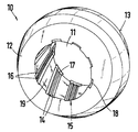
- the lubricant deposits are formed as groove structures with at least two longitudinal grooves from face to face of the bearing at an acute angle to the central axis of the Bearing bore are inclined.
- the stripes Due to the inclined orientation of the groove structures, the stripes can become of treads between the end faces of the bearing with their ends together rows, so that a shaft inserted into the bearing bore always at least partially connected to a lubricant depot and this via the entire scope of the wave. This increases the lubricating effect of the lubricant deposits significantly improved and the sintered plain bearing becomes Sufficiently lubricated shaft.
- the longitudinal grooves of the groove structures are closed in the area of the end faces, then that of the Longitudinal grooves of the groove structures do not absorb lubricant from the bearing emerge and is fully available for lubrication of the shaft.
- the longitudinal grooves can be deformed by a simple design Parts of the sintered storage facility must be closed.
- the distribution of the lubricant can the entire circumferential surface of the shaft can be improved by the fact that the ends of adjacent groove structures at least on the two end faces partially overlap.
- the introduction of the groove structures into the bearing bore is facilitated that the groove structures are at the same distance and therefore at the same distance Angular range are arranged to each other, since the angular position of the insertion tool can be maintained.
- the groove structures are completed by the fact that the longitudinal grooves Grooved tops are separated from each other and that the grooved tops with the in the Bearing bore inserted shaft is not load-bearing, but for lubricant transfer are at least partially in contact. This will over the porous grooved tops also the lubrication of the shaft in the initial phases of operation improved.
- a configuration for proven advantageous which is characterized in that the longitudinal grooves Depth of up to 0.5 mm and a width in the area of the bearing bore of 0.30 have up to 0.50 mm, the radii of the longitudinal grooves at least 0.05 mm amount, and that the grooved tips have the same dimensions in mirror image.
- the groove structures 15 are made of at least two longitudinal grooves 14 - in the exemplary embodiment 3 - formed, which are separated from each other by grooved tips 16.
- the groove tips 16 are mirror images of the longitudinal grooves 14 and correspondingly dimensioned equally.
- a longitudinal groove 14 can have a depth of up to 0.50 mm wide and 0.30 to 0.50 mm wide.
- the radii of the Longitudinal grooves 14 and the groove crests 16 can be at least 0.05 mm.
- the groove tops 16 are compressed low and are not load-bearing with the Shaft in contact to ensure a lubricating effect even during the start-up phases of the operation for reaching the wave.
- the groove structures 15 do not run parallel to the central axis of the bearing bore 11, but are inclined to this at an acute angle. There are neighboring ones Groove structures 15 on both end faces 12 and 13 with their opposite ones Ends strung together. The inclination of the groove structures 15 can also are chosen so that adjacent groove structures 15 with the opposite Ends on the end faces 12 and 13 at least partially overlap.
- the shaft inserted into the bearing bore 11 is therefore with a Part of its peripheral surface always in contact with a groove structure 15 and thus the lubrication is always over the entire circumference of the shaft - at least with a part of it - extended.
- the longitudinal grooves 14 are on two end faces 12 and 13 of the sintered plain bearing 10 closed, like the deformed parts 17 and 18 of the end faces 12 and 13 show. This can be done by an upsetting process can be achieved after the introduction of the longitudinal grooves 14.
- the outer edges of the end faces 12 and 13 of the sintered plain bearing 10 can also be used beveled in one phase.
Landscapes
- Engineering & Computer Science (AREA)
- General Engineering & Computer Science (AREA)
- Mechanical Engineering (AREA)
- Chemical & Material Sciences (AREA)
- Oil, Petroleum & Natural Gas (AREA)
- Sliding-Contact Bearings (AREA)
- Gears, Cams (AREA)
- Powder Metallurgy (AREA)
Abstract
Description
Claims (7)
- Sintergleitlager für Motoren und Getriebe mit einer von einer Lagerbohrung gebildeten und mit Schmierstoff aus Schmierstoffdepots im Lager beaufschlagbaren Lauffläche, bei dem die Lagerbohrung über den Umfang verteilt abwechselnd hoch verdichtete, kleinporige Laufflächen und von Stirnseite zu Stirnseite des Lagers niedrig verdichtete offenporige Schmierstoffdepots aufweist,
dadurch gekennzeichnet,dass die Schmierstoffdepots als Rillenstrukturen (15) mit mindestens zwei Längsrillen (14) gebildet sind, die von Stirnseite (12) zu Stirnseite (13) des Lagers (10) in spitzem Winkel zur Mittelachse der Lagerbohrung (11) geneigt sind. - Sintergleitlager nach Anspruch 1,
dadurch gekennzeichnet,dass die Längsrillen (14) der Rillenstrukturen (15) im Bereich der Stirnseiten (12, 13) geschlossen sind (17, 18). - Sintergleitlager nach Anspruch 2,
dadurch gekennzeichnet,dss die Längsrillen (14) durch verformte Teile (17, 18) des Lagers (10) verschlossen sind. - Sintergleitlager nach einem der Ansprüche 1 bis 3,
dadurch gekennzeichnet,dass die Enden benachbarter Rillenstrukturen (15) sich an den beiden Stirnseiten (12, 13) mindestens teilweise überlappen. - Sintergleitlager nach einem der Ansprüche 1 bis 4,
dadurch gekennzeichnet,dass die Rillenstrukturen (15) in gleichem Abstand und damit in gleichem Winkelbereich zueinander angeordnet sind. - Sintergleitlager nach einem der Ansprüche 1 bis 5,
dadurch gekennzeichnet,dass die Längsrillen (14) durch Rillenkuppen (16) voneinander getrennt sind unddass die Rillenkuppen (16) mit der in die Lagerbohrung (11) eingeführten Welle nichttragend, zur Schmierstoffübergabe jedoch zumindest teilweise in Kontakt stehen. - Sintergleitlager nach einem der Ansprüche 1 bis 6,
dadurch gekennzeichnet,dass die Längsrillen (14) eine Tiefe von bis zu 0,5 mm und eine Breite im Bereich der Lagerbohrung (11) von 0,30 bis 0,50 mm aufweisen, wobei die Radien der Längsrillen mindestens 0,05 mm betragen, unddass die Rillenkuppen (16) spiegelbildlich gleiche Abmessungen aufweisen.
Applications Claiming Priority (2)
| Application Number | Priority Date | Filing Date | Title |
|---|---|---|---|
| DE19947462 | 1999-10-02 | ||
| DE19947462A DE19947462C1 (de) | 1999-10-02 | 1999-10-02 | Sintergleitlager für Motoren und Getriebe |
Publications (3)
| Publication Number | Publication Date |
|---|---|
| EP1089002A2 true EP1089002A2 (de) | 2001-04-04 |
| EP1089002A3 EP1089002A3 (de) | 2004-01-28 |
| EP1089002B1 EP1089002B1 (de) | 2005-03-30 |
Family
ID=7924257
Family Applications (1)
| Application Number | Title | Priority Date | Filing Date |
|---|---|---|---|
| EP00120793A Expired - Lifetime EP1089002B1 (de) | 1999-10-02 | 2000-09-23 | Sintergleitlager für Motoren und Getriebe |
Country Status (4)
| Country | Link |
|---|---|
| US (1) | US6398416B1 (de) |
| EP (1) | EP1089002B1 (de) |
| AT (1) | ATE292254T1 (de) |
| DE (2) | DE19947462C1 (de) |
Cited By (1)
| Publication number | Priority date | Publication date | Assignee | Title |
|---|---|---|---|---|
| WO2004048162A1 (de) * | 2002-11-22 | 2004-06-10 | Robert Bosch Gmbh | Antriebseinheit mit gleitlager |
Families Citing this family (12)
| Publication number | Priority date | Publication date | Assignee | Title |
|---|---|---|---|---|
| DE10107485A1 (de) * | 2001-02-15 | 2002-09-12 | Bosch Gmbh Robert | Sintergleitlager mit mehreren Laufzonen |
| US20030219180A1 (en) * | 2002-05-22 | 2003-11-27 | Hui-Wen Huang | Oil-impregnated bearing |
| DE10312873A1 (de) | 2003-03-22 | 2004-10-07 | Gkn Sinter Metals Gmbh | Sintergleitlager mit kontinuierlicher Variation der Bohrungsverdichtung |
| DE102004012757A1 (de) * | 2004-03-15 | 2005-10-06 | Robert Bosch Gmbh | Gleitlager |
| KR101065507B1 (ko) | 2004-09-21 | 2011-09-19 | 현대중공업 주식회사 | 그루브형 라인 베어링 |
| WO2007122798A1 (ja) * | 2006-03-29 | 2007-11-01 | Hitachi Powdered Metals Co., Ltd. | すべり軸受 |
| US20090245934A1 (en) * | 2008-03-26 | 2009-10-01 | Chin-Lung Han | Bushing structure for sheathing a shaft of a toner supply member |
| JP2012515303A (ja) * | 2009-01-12 | 2012-07-05 | ダウ グローバル テクノロジーズ エルエルシー | 改良されたジャーナル軸受構造 |
| EP2218554A1 (de) * | 2009-02-12 | 2010-08-18 | Robert Bosch GmbH | Kraftbetriebenes Handwerkzeug |
| DE102014018992A1 (de) * | 2014-12-18 | 2016-06-23 | GM Global Technology Operations LLC (n. d. Ges. d. Staates Delaware) | Drehbare Welle für ein Kraftfahrzeug |
| CN105864279B (zh) * | 2016-06-08 | 2020-10-27 | 联想(北京)有限公司 | 动压轴承及其加工方法 |
| CN106704374A (zh) * | 2017-01-25 | 2017-05-24 | 雷勇兵 | 一种润滑油损失量少的油润滑滑动轴承 |
Family Cites Families (18)
| Publication number | Priority date | Publication date | Assignee | Title |
|---|---|---|---|---|
| US1194463A (en) * | 1916-08-15 | bache | ||
| US1339084A (en) * | 1919-06-12 | 1920-05-04 | United Lead Company | Bearing |
| US1398220A (en) * | 1921-01-31 | 1921-11-29 | Jr Edward Goodrich Acheson | Bearing |
| US1557137A (en) * | 1924-01-25 | 1925-10-13 | Ralph Curcio | Self-lubricating bearing and method of making it |
| US2153397A (en) * | 1937-10-15 | 1939-04-04 | Johnson Bronze Co | Machinable sinter bearing |
| CH227650A (de) * | 1942-05-02 | 1943-06-30 | Vogt Hans | Selbstschmierendes Kapillarlager. |
| US3441328A (en) * | 1966-10-20 | 1969-04-29 | Forbes M Hurley | Prelubricated bearing surface,and method of preparing the same |
| AT369145B (de) * | 1981-02-06 | 1982-12-10 | Miba Gleitlager Ag | Hochbelastbares gleitlager |
| DE3407678C1 (de) * | 1984-03-02 | 1985-09-19 | Bergische Achsenfabrik Fr. Kotz & Söhne, 5276 Wiehl | Lagerbuchse |
| JPH03209019A (ja) * | 1989-10-24 | 1991-09-12 | Sankyo Seiki Mfg Co Ltd | 焼結含油軸受 |
| JP3464051B2 (ja) * | 1994-08-30 | 2003-11-05 | Ntn株式会社 | 焼結含油軸受の製造方法 |
| KR970006950A (ko) * | 1995-07-14 | 1997-02-21 | 소결함유 축받이 및 그 제조방법 | |
| US5746516A (en) * | 1995-08-11 | 1998-05-05 | Hitachi Powdered Metals Co., Ltd. | Porous bearing system having internal grooves and electric motor provided with the same |
| JP3599886B2 (ja) * | 1996-03-08 | 2004-12-08 | 日立粉末冶金株式会社 | 動圧スラスト多孔質軸受 |
| KR100224000B1 (ko) * | 1996-08-19 | 1999-10-15 | 이형도 | 소결함유 베어링 |
| GB2322915B (en) * | 1997-03-06 | 2001-06-06 | Ntn Toyo Bearing Co Ltd | Hydrodynamic type porous oil-impregnated bearing |
| JP3962168B2 (ja) * | 1998-12-01 | 2007-08-22 | 日本電産サンキョー株式会社 | 動圧軸受装置及びその製造方法 |
| US6270259B1 (en) * | 1999-09-09 | 2001-08-07 | Emerson Electric Co. | Powdered metal sintered bearing with improved oil flow polygonal interior bore |
-
1999
- 1999-10-02 DE DE19947462A patent/DE19947462C1/de not_active Expired - Fee Related
-
2000
- 2000-09-23 DE DE50009901T patent/DE50009901D1/de not_active Expired - Fee Related
- 2000-09-23 EP EP00120793A patent/EP1089002B1/de not_active Expired - Lifetime
- 2000-09-23 AT AT00120793T patent/ATE292254T1/de not_active IP Right Cessation
- 2000-10-02 US US09/678,219 patent/US6398416B1/en not_active Expired - Fee Related
Cited By (1)
| Publication number | Priority date | Publication date | Assignee | Title |
|---|---|---|---|---|
| WO2004048162A1 (de) * | 2002-11-22 | 2004-06-10 | Robert Bosch Gmbh | Antriebseinheit mit gleitlager |
Also Published As
| Publication number | Publication date |
|---|---|
| EP1089002B1 (de) | 2005-03-30 |
| US6398416B1 (en) | 2002-06-04 |
| ATE292254T1 (de) | 2005-04-15 |
| DE19947462C1 (de) | 2000-10-26 |
| EP1089002A3 (de) | 2004-01-28 |
| DE50009901D1 (de) | 2005-05-04 |
Similar Documents
| Publication | Publication Date | Title |
|---|---|---|
| EP0753678B1 (de) | Gleitlager für eine Welle | |
| DE2365911C3 (de) | Bürstendichtung zwischen gegeneinander rotierenden Maschinenteilen | |
| EP1089002B1 (de) | Sintergleitlager für Motoren und Getriebe | |
| WO2007065415A1 (de) | Radialwälzlager, insbesondere einreihiges rillenwälzlager | |
| DE3732572C2 (de) | ||
| DE2005740C3 (de) | Gleitlagerkörper für die unmittelbare Aufnahme und hydrodynamisch geschmierte Lagerung sich drehender Wellen | |
| DE102009011336A1 (de) | Lanzeneinheit und Spindel mit einer solchen | |
| DE2737557A1 (de) | Kreuzgelenk-kupplung | |
| EP1044336B1 (de) | Sintergleitlager für motoren und getriebe | |
| EP1957811A1 (de) | Radialwälzlager, insbesondere einreihiges rillenwälzlager | |
| DE102021129190A1 (de) | Lagerkäfig für Zylinderrollen und Zylinderrollenlager mit einem solchen Lagerkäfig | |
| DE10205199A1 (de) | Getriebe mit Schmiernuten | |
| DE3905450C2 (de) | Gleitlager | |
| DE10216137A1 (de) | Verdrehgesicherte Anlaufscheibe | |
| DE19937567A1 (de) | Sintergleitlager für Motoren und Getriebe | |
| DE3522020A1 (de) | Mehrteile steuerwelle fuer waermekraftmaschinen | |
| EP1606525A1 (de) | Sintergleitlager mit kontinuierlicher variation der bohrungsverdichtung | |
| DE2631376B1 (de) | Kreuzkopfzapfenlager fuer Kolbenmaschinen,insbesondere fuer Dieselbrennkraftmaschinen | |
| WO2005038277A1 (de) | Gleitlager für eine welle | |
| DE19923739A1 (de) | Gleitlagereinheit für eine Kurbelwelle | |
| DE102010011000A1 (de) | Lanzeneinheit und Spindel mit einer solchen | |
| DE112019001424B4 (de) | Lagerbuchse für eine Welle eines Turboladers | |
| DE60131548T2 (de) | Rollenpumpe mit lagerbüchse | |
| DE10107485A1 (de) | Sintergleitlager mit mehreren Laufzonen | |
| DE19620477A1 (de) | Spiralverdichter |
Legal Events
| Date | Code | Title | Description |
|---|---|---|---|
| PUAI | Public reference made under article 153(3) epc to a published international application that has entered the european phase |
Free format text: ORIGINAL CODE: 0009012 |
|
| AK | Designated contracting states |
Kind code of ref document: A2 Designated state(s): AT BE CH CY DE DK ES FI FR GB GR IE IT LI LU MC NL PT SE |
|
| AX | Request for extension of the european patent |
Free format text: AL;LT;LV;MK;RO;SI |
|
| PUAL | Search report despatched |
Free format text: ORIGINAL CODE: 0009013 |
|
| AK | Designated contracting states |
Kind code of ref document: A3 Designated state(s): AT BE CH CY DE DK ES FI FR GB GR IE IT LI LU MC NL PT SE |
|
| AX | Request for extension of the european patent |
Extension state: AL LT LV MK RO SI |
|
| GRAP | Despatch of communication of intention to grant a patent |
Free format text: ORIGINAL CODE: EPIDOSNIGR1 |
|
| 17P | Request for examination filed |
Effective date: 20040728 |
|
| AKX | Designation fees paid |
Designated state(s): AT BE CH CY DE DK ES FI FR GB GR IE IT LI LU MC NL PT SE |
|
| GRAS | Grant fee paid |
Free format text: ORIGINAL CODE: EPIDOSNIGR3 |
|
| GRAA | (expected) grant |
Free format text: ORIGINAL CODE: 0009210 |
|
| AK | Designated contracting states |
Kind code of ref document: B1 Designated state(s): AT BE CH CY DE DK ES FI FR GB GR IE IT LI LU MC NL PT SE |
|
| PG25 | Lapsed in a contracting state [announced via postgrant information from national office to epo] |
Ref country code: IT Free format text: LAPSE BECAUSE OF FAILURE TO SUBMIT A TRANSLATION OF THE DESCRIPTION OR TO PAY THE FEE WITHIN THE PRESCRIBED TIME-LIMIT;WARNING: LAPSES OF ITALIAN PATENTS WITH EFFECTIVE DATE BEFORE 2007 MAY HAVE OCCURRED AT ANY TIME BEFORE 2007. THE CORRECT EFFECTIVE DATE MAY BE DIFFERENT FROM THE ONE RECORDED. Effective date: 20050330 Ref country code: GB Free format text: LAPSE BECAUSE OF FAILURE TO SUBMIT A TRANSLATION OF THE DESCRIPTION OR TO PAY THE FEE WITHIN THE PRESCRIBED TIME-LIMIT Effective date: 20050330 Ref country code: IE Free format text: LAPSE BECAUSE OF FAILURE TO SUBMIT A TRANSLATION OF THE DESCRIPTION OR TO PAY THE FEE WITHIN THE PRESCRIBED TIME-LIMIT Effective date: 20050330 Ref country code: NL Free format text: LAPSE BECAUSE OF FAILURE TO SUBMIT A TRANSLATION OF THE DESCRIPTION OR TO PAY THE FEE WITHIN THE PRESCRIBED TIME-LIMIT Effective date: 20050330 Ref country code: FI Free format text: LAPSE BECAUSE OF FAILURE TO SUBMIT A TRANSLATION OF THE DESCRIPTION OR TO PAY THE FEE WITHIN THE PRESCRIBED TIME-LIMIT Effective date: 20050330 |
|
| REG | Reference to a national code |
Ref country code: GB Ref legal event code: FG4D Free format text: NOT ENGLISH |
|
| REG | Reference to a national code |
Ref country code: CH Ref legal event code: EP |
|
| REF | Corresponds to: |
Ref document number: 50009901 Country of ref document: DE Date of ref document: 20050504 Kind code of ref document: P |
|
| REG | Reference to a national code |
Ref country code: IE Ref legal event code: FG4D Free format text: LANGUAGE OF EP DOCUMENT: GERMAN |
|
| PG25 | Lapsed in a contracting state [announced via postgrant information from national office to epo] |
Ref country code: DK Free format text: LAPSE BECAUSE OF FAILURE TO SUBMIT A TRANSLATION OF THE DESCRIPTION OR TO PAY THE FEE WITHIN THE PRESCRIBED TIME-LIMIT Effective date: 20050630 Ref country code: GR Free format text: LAPSE BECAUSE OF FAILURE TO SUBMIT A TRANSLATION OF THE DESCRIPTION OR TO PAY THE FEE WITHIN THE PRESCRIBED TIME-LIMIT Effective date: 20050630 |
|
| PG25 | Lapsed in a contracting state [announced via postgrant information from national office to epo] |
Ref country code: ES Free format text: LAPSE BECAUSE OF FAILURE TO SUBMIT A TRANSLATION OF THE DESCRIPTION OR TO PAY THE FEE WITHIN THE PRESCRIBED TIME-LIMIT Effective date: 20050711 |
|
| PG25 | Lapsed in a contracting state [announced via postgrant information from national office to epo] |
Ref country code: PT Free format text: LAPSE BECAUSE OF FAILURE TO SUBMIT A TRANSLATION OF THE DESCRIPTION OR TO PAY THE FEE WITHIN THE PRESCRIBED TIME-LIMIT Effective date: 20050907 |
|
| PG25 | Lapsed in a contracting state [announced via postgrant information from national office to epo] |
Ref country code: AT Free format text: LAPSE BECAUSE OF NON-PAYMENT OF DUE FEES Effective date: 20050923 Ref country code: CY Free format text: LAPSE BECAUSE OF FAILURE TO SUBMIT A TRANSLATION OF THE DESCRIPTION OR TO PAY THE FEE WITHIN THE PRESCRIBED TIME-LIMIT Effective date: 20050923 |
|
| PG25 | Lapsed in a contracting state [announced via postgrant information from national office to epo] |
Ref country code: LI Free format text: LAPSE BECAUSE OF NON-PAYMENT OF DUE FEES Effective date: 20050930 Ref country code: MC Free format text: LAPSE BECAUSE OF NON-PAYMENT OF DUE FEES Effective date: 20050930 Ref country code: LU Free format text: LAPSE BECAUSE OF NON-PAYMENT OF DUE FEES Effective date: 20050930 Ref country code: CH Free format text: LAPSE BECAUSE OF NON-PAYMENT OF DUE FEES Effective date: 20050930 Ref country code: BE Free format text: LAPSE BECAUSE OF NON-PAYMENT OF DUE FEES Effective date: 20050930 |
|
| NLV1 | Nl: lapsed or annulled due to failure to fulfill the requirements of art. 29p and 29m of the patents act | ||
| GBV | Gb: ep patent (uk) treated as always having been void in accordance with gb section 77(7)/1977 [no translation filed] |
Effective date: 20050330 |
|
| REG | Reference to a national code |
Ref country code: IE Ref legal event code: FD4D |
|
| PLBE | No opposition filed within time limit |
Free format text: ORIGINAL CODE: 0009261 |
|
| STAA | Information on the status of an ep patent application or granted ep patent |
Free format text: STATUS: NO OPPOSITION FILED WITHIN TIME LIMIT |
|
| 26N | No opposition filed |
Effective date: 20060102 |
|
| REG | Reference to a national code |
Ref country code: CH Ref legal event code: PL |
|
| EN | Fr: translation not filed | ||
| BERE | Be: lapsed |
Owner name: KARL SIMON G.M.B.H. & CO. KG Effective date: 20050930 |
|
| PG25 | Lapsed in a contracting state [announced via postgrant information from national office to epo] |
Ref country code: SE Free format text: LAPSE BECAUSE OF FAILURE TO SUBMIT A TRANSLATION OF THE DESCRIPTION OR TO PAY THE FEE WITHIN THE PRESCRIBED TIME-LIMIT Effective date: 20050630 |
|
| PG25 | Lapsed in a contracting state [announced via postgrant information from national office to epo] |
Ref country code: FR Free format text: LAPSE BECAUSE OF NON-PAYMENT OF DUE FEES Effective date: 20050930 |
|
| PG25 | Lapsed in a contracting state [announced via postgrant information from national office to epo] |
Ref country code: FR Free format text: LAPSE BECAUSE OF NON-PAYMENT OF DUE FEES Effective date: 20050330 |
|
| PGFP | Annual fee paid to national office [announced via postgrant information from national office to epo] |
Ref country code: DE Payment date: 20080919 Year of fee payment: 9 |
|
| PG25 | Lapsed in a contracting state [announced via postgrant information from national office to epo] |
Ref country code: DE Free format text: LAPSE BECAUSE OF NON-PAYMENT OF DUE FEES Effective date: 20100401 |