EP1089055B1 - Verfahren zum Vermessen der gegenseitigen Orientierung eines Hohlzylinders und einer zugeordneten Schnittfläche - Google Patents
Verfahren zum Vermessen der gegenseitigen Orientierung eines Hohlzylinders und einer zugeordneten Schnittfläche Download PDFInfo
- Publication number
- EP1089055B1 EP1089055B1 EP00120609A EP00120609A EP1089055B1 EP 1089055 B1 EP1089055 B1 EP 1089055B1 EP 00120609 A EP00120609 A EP 00120609A EP 00120609 A EP00120609 A EP 00120609A EP 1089055 B1 EP1089055 B1 EP 1089055B1
- Authority
- EP
- European Patent Office
- Prior art keywords
- hollow cylinder
- method step
- measuring
- laser gyroscope
- stored
- Prior art date
- Legal status (The legal status is an assumption and is not a legal conclusion. Google has not performed a legal analysis and makes no representation as to the accuracy of the status listed.)
- Expired - Lifetime
Links
- 238000000034 method Methods 0.000 title claims description 12
- 238000005259 measurement Methods 0.000 claims description 15
- 238000006073 displacement reaction Methods 0.000 claims 1
- 239000011343 solid material Substances 0.000 description 2
- 238000002485 combustion reaction Methods 0.000 description 1
- 238000012937 correction Methods 0.000 description 1
- 238000001514 detection method Methods 0.000 description 1
- 239000011521 glass Substances 0.000 description 1
- 239000002241 glass-ceramic Substances 0.000 description 1
- 238000003780 insertion Methods 0.000 description 1
- 230000037431 insertion Effects 0.000 description 1
- 239000000463 material Substances 0.000 description 1
- 238000000691 measurement method Methods 0.000 description 1
- 230000003287 optical effect Effects 0.000 description 1
- 238000012546 transfer Methods 0.000 description 1
- 230000001960 triggered effect Effects 0.000 description 1
Images


Classifications
-
- G—PHYSICS
- G01—MEASURING; TESTING
- G01B—MEASURING LENGTH, THICKNESS OR SIMILAR LINEAR DIMENSIONS; MEASURING ANGLES; MEASURING AREAS; MEASURING IRREGULARITIES OF SURFACES OR CONTOURS
- G01B11/00—Measuring arrangements characterised by the use of optical techniques
- G01B11/26—Measuring arrangements characterised by the use of optical techniques for measuring angles or tapers; for testing the alignment of axes
-
- G—PHYSICS
- G01—MEASURING; TESTING
- G01C—MEASURING DISTANCES, LEVELS OR BEARINGS; SURVEYING; NAVIGATION; GYROSCOPIC INSTRUMENTS; PHOTOGRAMMETRY OR VIDEOGRAMMETRY
- G01C21/00—Navigation; Navigational instruments not provided for in groups G01C1/00 - G01C19/00
- G01C21/10—Navigation; Navigational instruments not provided for in groups G01C1/00 - G01C19/00 by using measurements of speed or acceleration
- G01C21/12—Navigation; Navigational instruments not provided for in groups G01C1/00 - G01C19/00 by using measurements of speed or acceleration executed aboard the object being navigated; Dead reckoning
- G01C21/16—Navigation; Navigational instruments not provided for in groups G01C1/00 - G01C19/00 by using measurements of speed or acceleration executed aboard the object being navigated; Dead reckoning by integrating acceleration or speed, i.e. inertial navigation
-
- Y—GENERAL TAGGING OF NEW TECHNOLOGICAL DEVELOPMENTS; GENERAL TAGGING OF CROSS-SECTIONAL TECHNOLOGIES SPANNING OVER SEVERAL SECTIONS OF THE IPC; TECHNICAL SUBJECTS COVERED BY FORMER USPC CROSS-REFERENCE ART COLLECTIONS [XRACs] AND DIGESTS
- Y10—TECHNICAL SUBJECTS COVERED BY FORMER USPC
- Y10S—TECHNICAL SUBJECTS COVERED BY FORMER USPC CROSS-REFERENCE ART COLLECTIONS [XRACs] AND DIGESTS
- Y10S33/00—Geometrical instruments
- Y10S33/21—Geometrical instruments with laser
Definitions
- the invention relates to a device and a method for measuring the mutual orientation of a hollow cylinder and a cut surface assigned to it.
- a measurement problem in this regard occurs, for example, when checking a cylinder of an internal combustion engine, in particular in the case of large-volume diesel engines. Typical dimensions of the cylinders of such engines are in the decimeter to meter range.
- the high-precision detection of the relative position between the cylinder wall and a cut surface, which is defined by an end surface of such a hollow cylinder, is difficult and expensive with small wall thicknesses of the associated solid material.
- the orientation of two or more Hollow cylinders can be determined to each other by using the laser gyroscope at least once in contact with the wall of one Hollow cylinder is brought and in this way Orientation to a previously determined laboratory coordinate system is determined, and in a subsequent step the Orientations of the measured hollow cylinders with each other be compared.
- This cannot only be based on parallelism of the hollow cylinder axes are tested, but also the Compliance with a predetermined angular dimension, such as 60 ° can be checked.
- the invention is based on the knowledge that measurements of the aforementioned type in principle are angle measurements for which instead of mechanical measuring equipment, it is better to use electronic basis should be used.
- the solution of the illustrated is successful Measurement problems due to the fact that a highly accurate optical gyroscope is used, preferably in the form of a so-called Laser gyroscopes, whose precision is currently unsurpassed. It is recommended to use a three-axis gyroscope of this type to be provided, although for simpler measuring tasks of the named Type biaxial gyroscopes can also be used can.
- the hollow cylinder 20 shown in Fig. 1 is in a block 10 made of solid material.
- An assigned top Cutting area A (reference number 30) is through the periphery 22 of the hollow cylinder defined. From the surface normal of this Cutting area A is required to be as large as possible Precision parallel to the longitudinal axis of the hollow cylinder 20 is aligned. Checking this chess behavior designed when using the inventive The procedure using a laser gyroscope is amazing simple and requires a minimum of time with typical Time savings of 95% to 99% compared to previous ones Measurement methods. As shown in Fig.
- a laser gyroscope 40 from the inside to the The outer surface of the hollow cylinder 20 is attached, and by Triggering a (first) measurement taking its orientation in Held space.
- the registration of the orientation values can be done in the gyroscope 40 itself, or in the associated Computer 70, which is also a power supply for provides the gyroscope (see schematically drawn Connection cable 52).
- it is ensured that the recorded measured values are output at a later point in time can be e.g. by screen or electronically Data transfer.
- - Step one is to increase the Measurement accuracy advantageously repeated several times, in particular at various points on the hollow cylinder jacket.
- the laser gyro 40 is then turned off removed from the hollow cylinder.
- the support 60 has a cover plate with plane-parallel Surfaces and is preferably made of glass ceramic with very low coefficient of thermal expansion, they but can also be made of mirror glass. Furthermore is a base plate 50 of the same on the support 60 Material attached, but which only has centering functions and a central insertion of the pad 60 on the terminal periphery 22 of the hollow cylinder 20 enables.
- a (Second) measurement is triggered by the laser gyro.
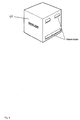
- the measuring device containing the laser gyro can take measurements have a housing with suitable high-precision manufactured measuring edges is provided (Fig. 3).
- first and second measured values with each other compared.
- the computer 70 can be practically immediately calculated and signaled whether and in which directions a misalignment of the cut surface 30 (e.g. one Cylinder head contact surface) compared to that through the Hollow cylinder wall defined longitudinal axis of the hollow cylinder is present.
- a misalignment of the cut surface 30 e.g. one Cylinder head contact surface
- These measurement results can be compared with the required Precision are represented, with an accuracy of far better than a tenth of a degree.
- the invention can also be used to Cut lines or end faces on other large dimensions Check hollow cylinders.
Landscapes
- Engineering & Computer Science (AREA)
- Radar, Positioning & Navigation (AREA)
- Remote Sensing (AREA)
- Physics & Mathematics (AREA)
- General Physics & Mathematics (AREA)
- Automation & Control Theory (AREA)
- Length Measuring Devices By Optical Means (AREA)
- Gyroscopes (AREA)
Description
Ein diesbezügliches Messproblem tritt beispielsweise bei der Überprüfung eines Zylinders einer Verbrennungskraftmaschine auf, insbesondere bei grossvolumigen Dieselmotoren. Typische Dimensionen der Zylinder solcher Motoren liegen im Dezimeterbis Meterbereich. Die hochgenaue Erfassung der Relativlage zwischen Zylinderwandung und einer Schnittfläche, welche durch eine Endfläche eines solchen Hohlzylinders definiert wird, gestaltet sich bei geringen Wandstärken des zugehörigen Massivmaterials als schwierig und aufwendig.
Claims (1)
- Verfahren zur messtechnischen Erfassung der gegenseitigen Orientierung eines Hohlzylinders und einer diesem zugeordneten Schnittfläche, bei dem in einem ersten Verfahrensschritt ein
hochgenau arbeitendes
Laser-Gyroskop (40) exakt an die Innenwand eines Hohlzylinders (20) angelegt wird,
in einem zweiten Verfahrensschritt die räumliche Orientierung des Laser-Gyroskops (40) nach zumindest zwei Winkelkoordinaten relativ zu einem Laborsystem elektronisch registriert und als ein erstes Messergebnis gespeichert wird, in einem dritten
Verfahrensschritt eine
hochgenau gefertigte
Auflage (60) auf die Schnittfläche (30) aufgesetzt wird, in einem vierten Verfahrensschritt das Laser-Gyroskop unter Zuhilfenahme der Auflage (60) indirekt auf die Schnittfläche (30) aufgesetzt wird,
in einem fünften Verfahrensschritt erneut die räumliche Orientierung des Laser-Gyroskops (40) nach zumindest zwei Winkelkoordinaten relativ zu einem Laborsystem elektronisch registriert und als ein zweites Messergebnis gespeichert wird, in einem sechsten Verfahrensschritt die gespeicherten ersten und zweiten Messergebnisse miteinander verglichen werden und der Wert eines ermittelten Fehlwinkels visualisiert oder in anderer Form, insbesondere akustisch, dargestellt wird.
Applications Claiming Priority (2)
| Application Number | Priority Date | Filing Date | Title |
|---|---|---|---|
| DE19947292 | 1999-10-01 | ||
| DE19947292A DE19947292A1 (de) | 1999-10-01 | 1999-10-01 | Vorrichtung und Verfahren zum Vermessen der gegenseitigen Orientierung eines Hohlzylinders und einer zugeordneten Schnittfläche |
Publications (2)
| Publication Number | Publication Date |
|---|---|
| EP1089055A1 EP1089055A1 (de) | 2001-04-04 |
| EP1089055B1 true EP1089055B1 (de) | 2002-06-26 |
Family
ID=7924141
Family Applications (1)
| Application Number | Title | Priority Date | Filing Date |
|---|---|---|---|
| EP00120609A Expired - Lifetime EP1089055B1 (de) | 1999-10-01 | 2000-09-21 | Verfahren zum Vermessen der gegenseitigen Orientierung eines Hohlzylinders und einer zugeordneten Schnittfläche |
Country Status (3)
| Country | Link |
|---|---|
| US (1) | US6516533B1 (de) |
| EP (1) | EP1089055B1 (de) |
| DE (2) | DE19947292A1 (de) |
Families Citing this family (6)
| Publication number | Priority date | Publication date | Assignee | Title |
|---|---|---|---|---|
| DE10115548C2 (de) * | 2001-03-28 | 2003-11-06 | Busch Dieter & Co Prueftech | Meßgerät zur Bestimmung der räumlichen Orientierung eines Körpers relativ zu einer Bezugsrichtung |
| DE20108419U1 (de) | 2001-05-18 | 2002-09-19 | Prüftechnik Dieter Busch AG, 85737 Ismaning | Orientierungsmessvorrichtung |
| DE102004020406A1 (de) * | 2004-04-23 | 2005-11-10 | Prüftechnik Dieter Busch AG | Messvorrichtung und Verfahren zum Ermitteln der Geradheit hohlzylindrischer oder hohlkegeliger Körper bzw. deren Orientierung relativ zueinander |
| US20090144999A1 (en) * | 2006-11-30 | 2009-06-11 | Lau Kam C | Interior contour measurement probe |
| KR101567770B1 (ko) * | 2015-06-26 | 2015-11-20 | 국방과학연구소 | 도수 운반형 포 발사체의 실시간 자세 결정을 위한 디지털 가늠자 |
| CN108827219A (zh) * | 2018-07-09 | 2018-11-16 | 北京石晶光电科技股份有限公司济源分公司 | 一种非接触式罗拉线偏角检测装置及检测方法 |
Family Cites Families (13)
| Publication number | Priority date | Publication date | Assignee | Title |
|---|---|---|---|---|
| GB2103793B (en) * | 1981-08-20 | 1985-10-30 | Sperry Sun Inc | Instrument for monitoring the direction of a borehole |
| US4521968A (en) * | 1982-10-12 | 1985-06-11 | Westinghouse Electric Corp. | Mapping system for an internal cylindrical surface |
| CH666961A5 (de) * | 1983-09-05 | 1988-08-31 | Magyar Optikai Muevek | Vertikale wellenkonstruktion zu kreiseltheodoliten mit zwei freiheitsgraden. |
| JPH01503559A (ja) * | 1987-06-12 | 1989-11-30 | バイスバルツ オズモンド | ホイール・アライメントの測定方法および装置 |
| US5274566A (en) | 1992-12-04 | 1993-12-28 | United Technologies Corporation | Aligning average axis of hollow workpiece cavity with rotary machine axis |
| US5426507A (en) * | 1993-04-19 | 1995-06-20 | Spectra-Physics Laserplane, Inc. | Laser-based pipe alignment device and method |
| JP2940403B2 (ja) | 1994-08-03 | 1999-08-25 | 株式会社日立製作所 | 並列計算機システムにおけるモニタデータ収集方法 |
| DE19546405A1 (de) * | 1995-12-12 | 1997-06-19 | Busch Dieter & Co Prueftech | Verfahren zum gegenseitigen Ausrichten von Körpern und Lagemeßsonde hierfür |
| DE29602453U1 (de) * | 1996-02-13 | 1996-04-11 | Bodenseewerk Gerätetechnik GmbH, 88662 Überlingen | Inertialsensor-Anordnung |
| US5801303A (en) * | 1996-11-15 | 1998-09-01 | Fel-Pro Incorporated | Method and gauge for correctly reassembling a V-engine |
| JP3587416B2 (ja) * | 1996-11-29 | 2004-11-10 | 新日本製鐵株式会社 | ロ−ル平行度測定装置 |
| JP3587415B2 (ja) | 1996-11-29 | 2004-11-10 | 新日本製鐵株式会社 | ロ−ル平行度測定装置 |
| US6044571A (en) * | 1997-08-13 | 2000-04-04 | Climax Portable Machine Tools, Inc. | Bore measurement apparatus and method |
-
1999
- 1999-10-01 DE DE19947292A patent/DE19947292A1/de not_active Withdrawn
-
2000
- 2000-09-21 EP EP00120609A patent/EP1089055B1/de not_active Expired - Lifetime
- 2000-09-21 DE DE50000240T patent/DE50000240D1/de not_active Expired - Lifetime
- 2000-10-02 US US09/676,777 patent/US6516533B1/en not_active Expired - Lifetime
Also Published As
| Publication number | Publication date |
|---|---|
| DE50000240D1 (de) | 2002-08-01 |
| US6516533B1 (en) | 2003-02-11 |
| EP1089055A1 (de) | 2001-04-04 |
| DE19947292A1 (de) | 2000-11-02 |
Similar Documents
| Publication | Publication Date | Title |
|---|---|---|
| DE60126900T2 (de) | Verfahren zur evaluation einer fehlerposition für ein bewegliches objekt und verbesserung der bewegungsgenauigkeit auf grundlage des gefundenen resultates | |
| DE102010038783B4 (de) | Verfahren und Programm zum Erkennen von geometrischen Fehlern | |
| EP2040026B1 (de) | Verfahren und System zur Kalibrierung einer Vorrichtung zur Formmessung einer spiegelnden Oberfläche | |
| DE3689335T2 (de) | Abweichungsmesssystem. | |
| EP2273229B1 (de) | Verfahren zur Bestimmung der 3D-Koordinaten eines Objekts | |
| EP1285224A1 (de) | Verfahren und vorrichtung zum bestimmen der 3d-form eines objektes | |
| DE202016008719U1 (de) | Scananordnung zum Scannen eines Objektes | |
| WO1997021980A1 (de) | Verfahren zum gegenseitigen ausrichten von körpern und lagemesssonde hierfür | |
| WO2001088465A1 (de) | Eindimensionales kalibriernormal | |
| EP2133659A1 (de) | Verfahren und Vorrichtung zur Ermittlung der Lage eines Sensors | |
| DE10048096A1 (de) | Verfahren zur Kalibrierung eines messenden Sensors auf einem Koordinatenmeßgerät | |
| DE102021209178A1 (de) | Verfahren und Vorrichtung zum Bestimmen von Relativposen und zur Kalibrierung bei einem Koordinatenmessgerät oder Roboter | |
| EP0563058B1 (de) | Verfahren und lagegeber zur lagebestimmung eines positionierkörpers relativ zu einem bezugskörper | |
| DE102007011603B4 (de) | Verfahren und Vorrichtung zum Bestimmen von Geometriedaten eines konischen Messobjekts | |
| EP1719472B1 (de) | Vorrichtungen und Verfahren zur automatischen Verifikation, Kalibrierung und Vermessung von Instrumenten für computer-assistierte Chirurgie | |
| EP1089055A1 (de) | Vorrichtung und Verfahren zum Vermessen der gegenseitigen Orientierung eines Hohlzylinders und einer zugeordneten Schnittfläche | |
| DE602004005388T2 (de) | Vorrichtung und Verfahren zum Messen und Analysieren der Form eines Objekts, sowie entsprechendes Programm | |
| DE102016212651B4 (de) | Verfahren zum Vermessen eines Werkstücks unter Verwendung von zumindest einem Referenzkörper | |
| DE102019102927A1 (de) | Verfahren und Vorrichtung zum Bestimmen von dimensionalen und/oder geometrischen Eigenschaften eines Messobjekts | |
| EP1202218A2 (de) | Verfahren zur Registration der Istbeschreibung eines Messobjekts mit einer Sollbeschreibung des Messobjekts | |
| DE102013011980A1 (de) | Verfahren zum Kalibrieren einer Vorrichtung | |
| DE102024100552B3 (de) | Verfahren zur Bestimmung wenigstens einer Absteckposition | |
| DE102023120070B3 (de) | Verfahren zum erkennen einer zielmagnetorientierung bei einem magnetischen positionssensor | |
| DE19711361A1 (de) | Prüfkörper für optische Industriemeßsysteme und Koordinatenmeßgeräte mit optischen Flächensensoren | |
| DE102019110729A1 (de) | Verfahren zur Ausrichtung mindestens eines Kalibrierkörpers und Vorrichtung zum dreidimensionalen optischen Vermessen von Objekten |
Legal Events
| Date | Code | Title | Description |
|---|---|---|---|
| PUAI | Public reference made under article 153(3) epc to a published international application that has entered the european phase |
Free format text: ORIGINAL CODE: 0009012 |
|
| 17P | Request for examination filed |
Effective date: 20010201 |
|
| AK | Designated contracting states |
Kind code of ref document: A1 Designated state(s): CH DE FR GB LI SE |
|
| AX | Request for extension of the european patent |
Free format text: AL;LT;LV;MK;RO;SI |
|
| 17Q | First examination report despatched |
Effective date: 20010326 |
|
| GRAG | Despatch of communication of intention to grant |
Free format text: ORIGINAL CODE: EPIDOS AGRA |
|
| GRAG | Despatch of communication of intention to grant |
Free format text: ORIGINAL CODE: EPIDOS AGRA |
|
| GRAH | Despatch of communication of intention to grant a patent |
Free format text: ORIGINAL CODE: EPIDOS IGRA |
|
| RTI1 | Title (correction) |
Free format text: METHOD FOR MEASURING THE RELATIVE ORIENTATION OF A HOLLOW CYLINDER AND AN ASSOCIATED PLANE CUT |
|
| GRAH | Despatch of communication of intention to grant a patent |
Free format text: ORIGINAL CODE: EPIDOS IGRA |
|
| AKX | Designation fees paid |
Free format text: CH DE FR GB LI SE |
|
| GRAA | (expected) grant |
Free format text: ORIGINAL CODE: 0009210 |
|
| AK | Designated contracting states |
Kind code of ref document: B1 Designated state(s): CH DE FR GB LI SE |
|
| REG | Reference to a national code |
Ref country code: GB Ref legal event code: FG4D Free format text: NOT ENGLISH |
|
| REG | Reference to a national code |
Ref country code: CH Ref legal event code: EP |
|
| REF | Corresponds to: |
Ref document number: 50000240 Country of ref document: DE Date of ref document: 20020801 |
|
| GBT | Gb: translation of ep patent filed (gb section 77(6)(a)/1977) |
Effective date: 20020819 |
|
| ET | Fr: translation filed | ||
| PLBE | No opposition filed within time limit |
Free format text: ORIGINAL CODE: 0009261 |
|
| STAA | Information on the status of an ep patent application or granted ep patent |
Free format text: STATUS: NO OPPOSITION FILED WITHIN TIME LIMIT |
|
| 26N | No opposition filed |
Effective date: 20030327 |
|
| PG25 | Lapsed in a contracting state [announced via postgrant information from national office to epo] |
Ref country code: CH Free format text: LAPSE BECAUSE OF NON-PAYMENT OF DUE FEES Effective date: 20040930 Ref country code: LI Free format text: LAPSE BECAUSE OF NON-PAYMENT OF DUE FEES Effective date: 20040930 |
|
| REG | Reference to a national code |
Ref country code: CH Ref legal event code: PL |
|
| PGFP | Annual fee paid to national office [announced via postgrant information from national office to epo] |
Ref country code: DE Payment date: 20140922 Year of fee payment: 15 |
|
| PGFP | Annual fee paid to national office [announced via postgrant information from national office to epo] |
Ref country code: SE Payment date: 20140923 Year of fee payment: 15 Ref country code: GB Payment date: 20140923 Year of fee payment: 15 |
|
| PGFP | Annual fee paid to national office [announced via postgrant information from national office to epo] |
Ref country code: FR Payment date: 20140917 Year of fee payment: 15 |
|
| REG | Reference to a national code |
Ref country code: DE Ref legal event code: R119 Ref document number: 50000240 Country of ref document: DE |
|
| REG | Reference to a national code |
Ref country code: SE Ref legal event code: EUG |
|
| GBPC | Gb: european patent ceased through non-payment of renewal fee |
Effective date: 20150921 |
|
| PG25 | Lapsed in a contracting state [announced via postgrant information from national office to epo] |
Ref country code: SE Free format text: LAPSE BECAUSE OF NON-PAYMENT OF DUE FEES Effective date: 20150922 |
|
| REG | Reference to a national code |
Ref country code: FR Ref legal event code: ST Effective date: 20160531 |
|
| PG25 | Lapsed in a contracting state [announced via postgrant information from national office to epo] |
Ref country code: DE Free format text: LAPSE BECAUSE OF NON-PAYMENT OF DUE FEES Effective date: 20160401 Ref country code: GB Free format text: LAPSE BECAUSE OF NON-PAYMENT OF DUE FEES Effective date: 20150921 |
|
| PG25 | Lapsed in a contracting state [announced via postgrant information from national office to epo] |
Ref country code: FR Free format text: LAPSE BECAUSE OF NON-PAYMENT OF DUE FEES Effective date: 20150930 |