EP1089059A2 - Codeur angulaire pour un rotor, en particulier pour une roue de véhicule à équilibrer - Google Patents
Codeur angulaire pour un rotor, en particulier pour une roue de véhicule à équilibrer Download PDFInfo
- Publication number
- EP1089059A2 EP1089059A2 EP00117153A EP00117153A EP1089059A2 EP 1089059 A2 EP1089059 A2 EP 1089059A2 EP 00117153 A EP00117153 A EP 00117153A EP 00117153 A EP00117153 A EP 00117153A EP 1089059 A2 EP1089059 A2 EP 1089059A2
- Authority
- EP
- European Patent Office
- Prior art keywords
- angle
- encoder according
- rotation
- reflectors
- rotation encoder
- Prior art date
- Legal status (The legal status is an assumption and is not a legal conclusion. Google has not performed a legal analysis and makes no representation as to the accuracy of the status listed.)
- Granted
Links
Images


Classifications
-
- G—PHYSICS
- G01—MEASURING; TESTING
- G01B—MEASURING LENGTH, THICKNESS OR SIMILAR LINEAR DIMENSIONS; MEASURING ANGLES; MEASURING AREAS; MEASURING IRREGULARITIES OF SURFACES OR CONTOURS
- G01B11/00—Measuring arrangements characterised by the use of optical techniques
- G01B11/26—Measuring arrangements characterised by the use of optical techniques for measuring angles or tapers; for testing the alignment of axes
- G01B11/275—Measuring arrangements characterised by the use of optical techniques for measuring angles or tapers; for testing the alignment of axes for testing wheel alignment
-
- G—PHYSICS
- G01—MEASURING; TESTING
- G01P—MEASURING LINEAR OR ANGULAR SPEED, ACCELERATION, DECELERATION, OR SHOCK; INDICATING PRESENCE, ABSENCE, OR DIRECTION, OF MOVEMENT
- G01P3/00—Measuring linear or angular speed; Measuring differences of linear or angular speeds
- G01P3/36—Devices characterised by the use of optical means, e.g. using infrared, visible, or ultraviolet light
-
- G—PHYSICS
- G01—MEASURING; TESTING
- G01D—MEASURING NOT SPECIALLY ADAPTED FOR A SPECIFIC VARIABLE; ARRANGEMENTS FOR MEASURING TWO OR MORE VARIABLES NOT COVERED IN A SINGLE OTHER SUBCLASS; TARIFF METERING APPARATUS; MEASURING OR TESTING NOT OTHERWISE PROVIDED FOR
- G01D5/00—Mechanical means for transferring the output of a sensing member; Means for converting the output of a sensing member to another variable where the form or nature of the sensing member does not constrain the means for converting; Transducers not specially adapted for a specific variable
- G01D5/26—Mechanical means for transferring the output of a sensing member; Means for converting the output of a sensing member to another variable where the form or nature of the sensing member does not constrain the means for converting; Transducers not specially adapted for a specific variable characterised by optical transfer means, i.e. using infrared, visible, or ultraviolet light
- G01D5/32—Mechanical means for transferring the output of a sensing member; Means for converting the output of a sensing member to another variable where the form or nature of the sensing member does not constrain the means for converting; Transducers not specially adapted for a specific variable characterised by optical transfer means, i.e. using infrared, visible, or ultraviolet light with attenuation or whole or partial obturation of beams of light
- G01D5/34—Mechanical means for transferring the output of a sensing member; Means for converting the output of a sensing member to another variable where the form or nature of the sensing member does not constrain the means for converting; Transducers not specially adapted for a specific variable characterised by optical transfer means, i.e. using infrared, visible, or ultraviolet light with attenuation or whole or partial obturation of beams of light the beams of light being detected by photocells
- G01D5/347—Mechanical means for transferring the output of a sensing member; Means for converting the output of a sensing member to another variable where the form or nature of the sensing member does not constrain the means for converting; Transducers not specially adapted for a specific variable characterised by optical transfer means, i.e. using infrared, visible, or ultraviolet light with attenuation or whole or partial obturation of beams of light the beams of light being detected by photocells using displacement encoding scales
- G01D5/34707—Scales; Discs, e.g. fixation, fabrication, compensation
- G01D5/34715—Scale reading or illumination devices
Definitions
- the invention relates to a rotary encoder for a rotor, in particular a motor vehicle wheel to be balanced, with a Emitters and reflectors in the form of reflective Surfaces on a rotating circular path at equal angular intervals are arranged from each other and emitted by the emitter Reflect light, at least one detector, which the reflected light receives and appropriate signals delivers, and one connected to the at least one detector Evaluation device, which the signals for a Evaluates angle of rotation detection.
- Such an angle encoder is known (Ram S. Krishnan et al, A Miniature Surface Mount Reflective Optical Shaft Encoder, Hewlett-Packard Journal, December 1996, pages 1 to 6).
- the reflectors are Maintaining their flat reflective surfaces in a circular shape on one side one fixed to the rotor, in particular a shaft connected disc around the axis of rotation of the disc and the rotor arranged. This results in an additional one Device effort and space requirements for a functional Arrangement of the reflectors opposite the emitter and the detector or detectors, since the reflective Surfaces in a plane perpendicular to the axis of rotation extend.
- a main shaft on a balancing machine When recording the angular position, speed and direction of rotation a main shaft on a balancing machine become incremental encoders used in which light sensors one or several light sources, especially in the form of light emitting diodes, face each other. There is one between the light source and sensors Perforated, slotted or toothed washer arranged with the Main shaft of the balancing machine rotates (US 4,457,172).
- the additional encoder are used to record the absolute angular positions of the rotor an additional zero mark as a hole, slot or tooth and an associated one Detector required. Also extend in this arrangement the elements indicating the angular increments in one plane perpendicular to the axis of rotation.
- the object of the invention is a rotary encoder of the aforementioned Way of creating a reduced Device effort and space is required.
- the reflectors are reflective Areas or surface sections are formed on the circumference a circular cylinder surface of a rotating with the rotor Rotated part or arranged on a circular cylindrical surface of the rotor.
- the reflecting parts become Areas that are consecutive on the circumference are arranged one by one by the emitter preferably continuously passed beam.
- the reflective surfaces or surface sections are arranged in their sequence so that they are discrete direct the reflected rays onto the detector. Hereby one achieves an increment in angular positions, which correspond to the respective reflective surface sections.
- the respective surface sections can immediately adjoin each other and a continuous reflective tape with distinguishing features of the individual surface sections exhibit.
- the respective surface sections can be used for this Surface designs deviating from the circular cylindrical shape exhibit.
- circular cylindrical surfaces can also be used for the respective surface sections are used, the Radius of the respective circular cylinder area from the radius of the Circle that the circular cylinder surface has which the surface sections are arranged.
- each surface section can be between infinity, i.e. between a flat surface and the radius of the circular cylinder surface, on which the reflectors are arranged, lie.
- the surface sections have a parabolic or elliptical cross section.
- the reflective surface sections a convex or with respect to the emitter or detector have a concave shape.
- the reflective surface sections on a flexible band be arranged directly in a row, this flexible band around the circular cylinder surface of the rotor or Turned part is looped.
- the reflectors are on surfaces from parallel to the axis of the circular cylinder surface Webs formed.
- the webs between two strips of material be arranged and integral with these to be connected to a band.
- This band owns in the area of Bars and the strip of material flat or curved surfaces.
- the tape to place it on the circular cylinder surface adapt the surfaces of the strips of material Circular cylindrical shape.
- the webs can be flat Keep areas.
- the width of the webs, i.e. H. their expansion in the circumferential direction of the circular cylinder surface is one Fraction of a millimeter, for example approximately 0.3 mm.
- the turned part requires practically no space, because of this the rotor diameter or the turned part diameter only is increased insignificantly by the thickness of the band.
- the Reflectors have the same angular distances from each other. For Achieving an absolute angle reference can be between two Reflectors one of the other equal angular distances deviate angular distance. This will, for example reached a zero mark.
- the one with the invention created polygon mirror, its reflectors (specular Surfaces) around the circumference of the circular cylinder surface are, can also consist of a rigid molded part, in particular Plastic are formed.
- the reflective surface sections the reflectors can be separated by metal, in particular galvanic metal deposition.
- the molded part can be a plastic injection molded part preferably be in the form of a sleeve.
- the molded part can do that with form rotating part rotating with the rotor. Because the immediately lined up reflective surface sections through the detector can be distinguished from one another, a continuous reflective coating can be used.
- the respective reflectors emitted beam (light beam) focused so that its Focus on the flat surface of the respective reflector lies.
- the beam reflected by the respective reflector becomes during the rotation, within the area of each Reflector depending on the changing angle of rotation distracted and can be arranged by several in a row Detectors are received.
- a detector it is also possible for a detector to have multiple photosensitive Has sensors on which the respective Reflector deflected reflected beam during rotation one after the other.
- the detectors or sensors are in the essentially arranged side by side in the direction of rotation. she can also be arranged in a straight line. In however, they are preferably on a circular arc shape about the axis of rotation. A reversal of the direction of rotation can thereby be recognized that the light beam on the sensor or detector is directed longer, at which the direction of rotation reversal he follows. The from the detectors or sensors given signals are evaluated accordingly.
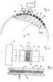
- the rotary encoder shown in the figures has one Emitter 1, which preferably continuously light in Emits direction on reflectors 2.
- the reflectors 2 reflect the light and the reflected light is from one or more detectors 3 received.
- the reflectors 2 are made of discrete reflective surfaces or surface sections formed on a band 10 and are, for example on webs 11 that pass between two Strips 9 are arranged ( Figure 3).
- the tape 10 can be made Metal, especially hard nickel or a metallized Plastic film exist ( Figure 3).
- the surfaces of the two strips 9 and the webs 11 are flat (plan).
- To achieve the angular coding for a rotor 6 the band 10 around a rotating part 7, which for example as Main shaft 12 of a balancing machine can be formed, placed.
- the band is located on a circular cylindrical surface 5 of the rotating part 7 or the main shaft 12 of the balancing machine.
- the main shaft 12 and the rotating part 7 are rotatably with the rotor 6, which for example a motor vehicle wheel can be connected. This is done in a known manner Way by fastening and / or clamping means. if the The unbalance of the main shaft is to be determined the rotor. With the arrangement of the band 10 on the circular cylinder surface 5 fit the continuous material strips 9 of the band on the circular cylinder surface 5.
- the non-reflective sections between the reflectors 2 are removed from the Band 10 won, so that the webs 11 are formed.
- In the Arrangement on the circular cylindrical surface 5 extend Web 11 and the reflectors 2 formed thereon in the axial Direction, d. H. parallel to the axis 8 about which the rotor 6 and turn the rotating part 7 or the main shaft 12.
- the webs can be produced by so-called electroforming his.
- the metallic tape with a photosensitive Resist coated and by subsequent exposure the structures are applied to the resist using a mask transfer.
- resist-free areas the metal is built up by electrodeposition and thus the formation of the webs.
- the arrangement of a polygon mirror is thereby achieved the circular cylindrical surface of the rotatably connected to the rotor 6 Rotating part 7 or the main shaft 12 of a balancing machine.
- the angular position changes respective mirror surface of a reflector 7 to the emitter 1 and the at least one detector 3.
- the emitter 1 transmits in particular focused light on the rotating circular cylinder surface 5 out.
- the light hits the reflective one flat surfaces of the reflectors 2. That of the reflectors 2 reflected light is emitted by the at least one detector 3 received and this generates a corresponding signal.
- This is in an evaluation device connected to the detector 3 4 evaluated for a rotation angle detection.
- the evaluation of the signals supplied by the detector 3 can also for determining the speed and direction of rotation of the rotor 6 can be evaluated.
- This molding 13 is preferably by a plastic injection molded part formed and has a sleeve shape.
- the molding 13 can be on a rotor or a part connected to the rotor be put on.
- the illustrated embodiment of the Figures 4 and 5 is the sleeve-shaped molding on the main shaft 12 of the balancing machine.
- the reflectors 2 from with respect to the emitter 1 or the detector 3 convexly curved surface sections (Fig. 6) or concave curved surface sections (Fig. 7) educated.
- the surface sections forming the reflectors 2 can be lined up directly on a tape 10 or a molded part 13 may be provided.
- a continuous reflective coating achieves the reflector property. Because the individual reflectors are geometrical their abutting edges distinguishable from each other are, you also win with continuous reflective Coating discrete surface sections, which are used for determination the individual angle of rotation in the evaluation device can be evaluated.
- the emitter 1 and the detector 3 are in one unit 20 arranged.
- This assembly 20 is together with the evaluation device 4 arranged on a carrier plate 21.
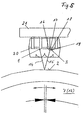
- the Emitter 1 sends a focused light beam 14 onto the respective reflector 2 opposite component 20, as can also be seen in detail from FIG. 6.
- At the rotation about the axis of rotation 8 becomes one of the respective Reflector 2 reflected beam 15 depending on the Deflection angle change deflected with different deflection angles and strikes one next to the other in the direction of deflection photosensitive sensors 16, 17, 18 and 19, which on Detector 3 are provided ( Figure 5). So that hits from beam 15 reflected at a respective reflector 2 Rotation in one direction in succession to the sensors 16 to 19 on.
- the first sensor 16 and the third sensor 18 are connected to a differential amplifier, which as an output signal the output signal denoted by A in FIG. 4 supplies.
- the second sensor 17 and the fourth sensor 19 are connected to another differential amplifier, which a Output signal B ( Figure 4) provides. This will make the Differences in brightness at the respective sensors, while a mirror surface of the reflector 2 on the assembly 20 moved over, evaluated.
- the reflected light beam no longer strikes the sensors. However, the one from the following reflector 2 hits reflected light beam 15 again when changing the rotational angle position of the rotor in succession to the sensors 16 to 19.
- the absolute angular reference to the rotor 7 or the main shaft 12 may be due to an irregularity in the division of the sealing surfaces around axis 8 become. This position can be, for example, the zero position of the Position counter in the rotary encoder.
- a reversal of the direction of rotation can be recorded in that when the state of the output signal A changes State of the output signal B ( Figure 4) is evaluated.
- the rotary encoder (incremental encoder) of the invention is insensitive to axial displacements.
- the number of Signal lines and end interference filters can be connected to a respective Number of two can be reduced.
- the one from the reflectors 2 The polygon mirror formed can, as explained, be relative be formed thin sleeve or band, which is the diameter of the rotating part or rotor only slightly enlarged. A space-saving arrangement of the rotary encoder is achieved.
Landscapes
- Physics & Mathematics (AREA)
- General Physics & Mathematics (AREA)
- Engineering & Computer Science (AREA)
- Electromagnetism (AREA)
- Power Engineering (AREA)
- Optical Transform (AREA)
- Length Measuring Devices By Optical Means (AREA)
Applications Claiming Priority (4)
| Application Number | Priority Date | Filing Date | Title |
|---|---|---|---|
| DE19946486 | 1999-09-28 | ||
| DE19946486 | 1999-09-28 | ||
| DE10020247A DE10020247B4 (de) | 1999-09-28 | 2000-04-25 | Drehwinkelgeber für einen Rotor, insbesondere ein auswuchtendes Kraftfahrzeugrad |
| DE10020247 | 2000-04-25 |
Publications (3)
| Publication Number | Publication Date |
|---|---|
| EP1089059A2 true EP1089059A2 (fr) | 2001-04-04 |
| EP1089059A3 EP1089059A3 (fr) | 2004-09-08 |
| EP1089059B1 EP1089059B1 (fr) | 2007-09-26 |
Family
ID=26005457
Family Applications (1)
| Application Number | Title | Priority Date | Filing Date |
|---|---|---|---|
| EP00117153A Expired - Lifetime EP1089059B1 (fr) | 1999-09-28 | 2000-08-10 | Machine d'équilibrage de roue pour une roue de véhicule avec codeur angulaire compact |
Country Status (6)
| Country | Link |
|---|---|
| US (1) | US6639206B1 (fr) |
| EP (1) | EP1089059B1 (fr) |
| JP (1) | JP4780825B2 (fr) |
| KR (1) | KR20010030477A (fr) |
| CN (1) | CN1186591C (fr) |
| ES (1) | ES2293878T3 (fr) |
Cited By (1)
| Publication number | Priority date | Publication date | Assignee | Title |
|---|---|---|---|---|
| EP3121577A1 (fr) | 2015-07-24 | 2017-01-25 | Snap-on Equipment Srl a unico socio | Unité et ensemble de mesure pour mesurer des forces de déséquilibre |
Families Citing this family (59)
| Publication number | Priority date | Publication date | Assignee | Title |
|---|---|---|---|---|
| NZ530439A (en) * | 2001-04-20 | 2004-11-26 | Lavipharm Lab Inc | Intraoral delivery of nicotine for smoking cessation |
| KR100427936B1 (ko) * | 2001-06-28 | 2004-04-28 | 현대자동차주식회사 | 크랭크축의 타겟 휠 |
| KR20030015497A (ko) * | 2001-08-16 | 2003-02-25 | 세진전자 주식회사 | 스티어링 휠의 각도 및 회전수 감지장치 |
| US7881896B2 (en) | 2002-02-14 | 2011-02-01 | Faro Technologies, Inc. | Portable coordinate measurement machine with integrated line laser scanner |
| US7265336B2 (en) * | 2003-12-01 | 2007-09-04 | Avago Technologies Ecbu Ip (Singapore) Pte. Ltd. | Encoder utilizing a reflective cylindrical surface |
| US7469839B2 (en) * | 2005-09-14 | 2008-12-30 | Avago Technologies Ecbu Ip (Singapore) Pte. Ltd. | Reflective optical encoder |
| US7552873B2 (en) * | 2005-09-14 | 2009-06-30 | Avago Technologies Ecbu Ip (Singapore) Pte. Ltd. | Transmissive optical encoder |
| US7358481B2 (en) * | 2006-03-06 | 2008-04-15 | Avago General Ip Pte Ltd | Reflective encoder with three-dimensional code carrier |
| US20070241271A1 (en) * | 2006-04-14 | 2007-10-18 | Chin Yee L | Reflection-based optical encoders having no code medium |
| EP1890113A1 (fr) * | 2006-08-18 | 2008-02-20 | Leica Geosystems AG | Capteur angulaire optoélectronique et procédé destiné à la détermination d'un angle de rotation autour d'un axe |
| JP4912212B2 (ja) * | 2007-05-09 | 2012-04-11 | ジャパン・ハムワージ株式会社 | 舵取機の舵角検出装置 |
| CN101358841B (zh) * | 2007-08-01 | 2010-06-16 | 鸿富锦精密工业(深圳)有限公司 | 色轮参数检测系统和方法 |
| CN101358840B (zh) * | 2007-08-01 | 2010-06-23 | 鸿富锦精密工业(深圳)有限公司 | 色轮参数检测系统和方法 |
| DE102009020921A1 (de) * | 2009-05-12 | 2010-11-18 | Krones Ag | Vorrichtung und Verfahren zum Ausrichten von Behältern, insbesondere Flaschen, in einer Etikettiermaschine |
| ITTO20120540A1 (it) * | 2012-06-20 | 2013-12-21 | M & B Engineering S R L | Macchina e metodo per l'equilibratura delle ruote di un veicolo |
| CN103245284A (zh) * | 2013-05-14 | 2013-08-14 | 福州大学 | 一种基于陀螺仪芯片的方向盘转角测量方法及其装置 |
| US9753436B2 (en) | 2013-06-11 | 2017-09-05 | Apple Inc. | Rotary input mechanism for an electronic device |
| CN103335782B (zh) * | 2013-06-13 | 2016-08-10 | 苏州市丹纺纺织研发有限公司 | 一种织机轴位偏移监测系统 |
| JP6345782B2 (ja) | 2013-08-09 | 2018-06-20 | アップル インコーポレイテッド | 電子デバイス用のタクタイルスイッチ |
| US10394325B2 (en) | 2013-12-10 | 2019-08-27 | Apple Inc. | Input friction mechanism for rotary inputs of electronic devices |
| US10048802B2 (en) | 2014-02-12 | 2018-08-14 | Apple Inc. | Rejection of false turns of rotary inputs for electronic devices |
| US10190891B1 (en) | 2014-07-16 | 2019-01-29 | Apple Inc. | Optical encoder for detecting rotational and axial movement |
| KR102239316B1 (ko) | 2014-09-02 | 2021-04-13 | 애플 인크. | 웨어러블 전자 디바이스 |
| US10145712B2 (en) * | 2014-09-09 | 2018-12-04 | Apple Inc. | Optical encoder including diffuser members |
| JP6614883B2 (ja) * | 2014-12-01 | 2019-12-04 | キヤノン株式会社 | 操作部材及び電子機器 |
| US9602706B2 (en) | 2014-12-01 | 2017-03-21 | Canon Kabushiki Kaisha | Rotatable operating member and electronic device having the same |
| KR102441844B1 (ko) * | 2015-02-04 | 2022-09-08 | 삼성전자주식회사 | 회전체를 제어하기 위한 방법 및 그 전자 장치 |
| WO2016141228A1 (fr) | 2015-03-05 | 2016-09-09 | Apple Inc. | Encodeur optique doté de propriétés optiques dépendant de la direction |
| US9651405B1 (en) | 2015-03-06 | 2017-05-16 | Apple Inc. | Dynamic adjustment of a sampling rate for an optical encoder |
| JP6479997B2 (ja) | 2015-03-08 | 2019-03-06 | アップル インコーポレイテッドApple Inc. | 回転可能かつ並進可能な入力機構のための圧縮可能な封止 |
| US10018966B2 (en) | 2015-04-24 | 2018-07-10 | Apple Inc. | Cover member for an input mechanism of an electronic device |
| US9816899B2 (en) | 2015-07-24 | 2017-11-14 | Snap-On Equipment Srl A Unico Socio | Communication system for a tyre service machine and measuring unit for being used with such communication system |
| EP3121578B1 (fr) | 2015-07-24 | 2023-05-10 | Snap-on Equipment Srl a unico socio | Système de communication pour une machine de service de pneu et unité de mesure destinée à être utilisée avec un tel système de communication |
| US10503271B2 (en) | 2015-09-30 | 2019-12-10 | Apple Inc. | Proximity detection for an input mechanism of an electronic device |
| US9891651B2 (en) | 2016-02-27 | 2018-02-13 | Apple Inc. | Rotatable input mechanism having adjustable output |
| US10551798B1 (en) | 2016-05-17 | 2020-02-04 | Apple Inc. | Rotatable crown for an electronic device |
| US10061399B2 (en) | 2016-07-15 | 2018-08-28 | Apple Inc. | Capacitive gap sensor ring for an input device |
| US10019097B2 (en) | 2016-07-25 | 2018-07-10 | Apple Inc. | Force-detecting input structure |
| WO2018107342A1 (fr) * | 2016-12-12 | 2018-06-21 | 华为技术有限公司 | Encodeur optique à déplacement angulaire réfléchissant |
| US10664074B2 (en) | 2017-06-19 | 2020-05-26 | Apple Inc. | Contact-sensitive crown for an electronic watch |
| US10962935B1 (en) | 2017-07-18 | 2021-03-30 | Apple Inc. | Tri-axis force sensor |
| US10203662B1 (en) | 2017-09-25 | 2019-02-12 | Apple Inc. | Optical position sensor for a crown |
| US11360440B2 (en) | 2018-06-25 | 2022-06-14 | Apple Inc. | Crown for an electronic watch |
| JP7130472B2 (ja) * | 2018-07-05 | 2022-09-05 | 株式会社ミツトヨ | 光学式角度センサ |
| US11561515B2 (en) | 2018-08-02 | 2023-01-24 | Apple Inc. | Crown for an electronic watch |
| US12259690B2 (en) | 2018-08-24 | 2025-03-25 | Apple Inc. | Watch crown having a conductive surface |
| US11181863B2 (en) | 2018-08-24 | 2021-11-23 | Apple Inc. | Conductive cap for watch crown |
| CN209560398U (zh) | 2018-08-24 | 2019-10-29 | 苹果公司 | 电子表 |
| CN209625187U (zh) | 2018-08-30 | 2019-11-12 | 苹果公司 | 电子手表和电子设备 |
| US11194298B2 (en) | 2018-08-30 | 2021-12-07 | Apple Inc. | Crown assembly for an electronic watch |
| CN109490900A (zh) * | 2019-01-03 | 2019-03-19 | 深圳至汉装备科技有限公司 | 一种传感器 |
| US11194299B1 (en) | 2019-02-12 | 2021-12-07 | Apple Inc. | Variable frictional feedback device for a digital crown of an electronic watch |
| US11662230B2 (en) | 2020-05-04 | 2023-05-30 | Saudi Arabian Oil Company | Recorder for shaft rotation verification |
| US11550268B2 (en) | 2020-06-02 | 2023-01-10 | Apple Inc. | Switch module for electronic crown assembly |
| CN116507885A (zh) * | 2020-11-06 | 2023-07-28 | 松下知识产权经营株式会社 | 编码器 |
| CN112697182A (zh) * | 2020-12-02 | 2021-04-23 | 上海力申科学仪器有限公司 | 一种电动手术台无磨损长度与角度的测控装置及其测控方法 |
| US12092996B2 (en) | 2021-07-16 | 2024-09-17 | Apple Inc. | Laser-based rotation sensor for a crown of an electronic watch |
| US12189347B2 (en) | 2022-06-14 | 2025-01-07 | Apple Inc. | Rotation sensor for a crown of an electronic watch |
| US12596334B2 (en) | 2023-02-07 | 2026-04-07 | Apple Inc. | Crown for an electronic watch |
Family Cites Families (21)
| Publication number | Priority date | Publication date | Assignee | Title |
|---|---|---|---|---|
| US2685083A (en) * | 1951-06-05 | 1954-07-27 | Telecomputing Corp | Photoelectric signal generator for position indicators |
| US3770970A (en) * | 1972-03-15 | 1973-11-06 | Trump Ross Ind Controls Inc | Shaft angle encoder |
| JPS5953506B2 (ja) * | 1978-06-13 | 1984-12-25 | 日産自動車株式会社 | 回転速度検出装置 |
| US4387299A (en) * | 1979-06-25 | 1983-06-07 | Yazaki Sogyo Kabushiki Kaisha | Travel-distance signal generator for vehicles |
| JPS5734457A (en) * | 1980-08-08 | 1982-02-24 | Nec Corp | Rotation measuring apparatus |
| JPS60118913U (ja) * | 1984-01-18 | 1985-08-12 | アルプス電気株式会社 | 反射型光学式ロ−タリ−エンコ−ダ |
| US4567467A (en) * | 1984-02-21 | 1986-01-28 | Towmotor Corporation | Angular rotary position encoder |
| JPS63157017A (ja) * | 1986-12-22 | 1988-06-30 | Toshiba Corp | 回転変位計測装置 |
| JPS6415603A (en) * | 1987-07-09 | 1989-01-19 | Aisin Aw Co | Steering sensor |
| JPS6475913A (en) * | 1987-09-18 | 1989-03-22 | Hitachi Ltd | Rotary angle detecting apparatus |
| KR920005244B1 (ko) * | 1988-06-29 | 1992-06-29 | 주식회사 금성사 | 자기테이프 기록장치의 비접촉 회전식 모드 스위치장치 |
| CH680240A5 (fr) * | 1988-06-30 | 1992-07-15 | Politechnika Warszawska | |
| JP2709088B2 (ja) * | 1988-08-24 | 1998-02-04 | 株式会社リコー | 回転量測定方法 |
| US5385045A (en) * | 1992-07-15 | 1995-01-31 | Fmc Corporation | Tire changing and balancing machine |
| KR950000455Y1 (ko) * | 1992-09-09 | 1995-01-27 | 배순훈 | 테이프 레코더의 테이프 잔량 검출장치 |
| US5329121A (en) * | 1993-02-25 | 1994-07-12 | The United States Of America As Represented By The Administrator Of The National Aeronautics And Space Administration | Rotary encoding device with polygonal reflector and centroid detection |
| KR0133875Y1 (ko) * | 1993-08-16 | 1999-03-20 | 김광호 | 릴디스크의 회전속도 감지장치 |
| JPH09166413A (ja) * | 1995-12-15 | 1997-06-24 | Shimadzu Corp | 光学的変位検出装置 |
| KR970071598A (ko) * | 1996-04-30 | 1997-11-07 | 배순훈 | 전자제품의 모드 판별 장치 |
| US6194709B1 (en) * | 1998-10-26 | 2001-02-27 | Eaton Corporation | Rotary position sensor/transducer employing rotor having color filtering |
| DE19860106B4 (de) * | 1998-12-23 | 2008-02-07 | Pwb-Ruhlatec Industrieprodukte Gmbh | Taktlineal oder Taktscheibe und Verfahren zu seiner Herstellung |
-
2000
- 2000-08-10 ES ES00117153T patent/ES2293878T3/es not_active Expired - Lifetime
- 2000-08-10 EP EP00117153A patent/EP1089059B1/fr not_active Expired - Lifetime
- 2000-09-13 US US09/661,466 patent/US6639206B1/en not_active Expired - Lifetime
- 2000-09-23 KR KR1020000055951A patent/KR20010030477A/ko not_active Withdrawn
- 2000-09-26 CN CNB00124647XA patent/CN1186591C/zh not_active Expired - Lifetime
- 2000-09-28 JP JP2000296986A patent/JP4780825B2/ja not_active Expired - Lifetime
Cited By (1)
| Publication number | Priority date | Publication date | Assignee | Title |
|---|---|---|---|---|
| EP3121577A1 (fr) | 2015-07-24 | 2017-01-25 | Snap-on Equipment Srl a unico socio | Unité et ensemble de mesure pour mesurer des forces de déséquilibre |
Also Published As
| Publication number | Publication date |
|---|---|
| CN1302740A (zh) | 2001-07-11 |
| KR20010030477A (ko) | 2001-04-16 |
| JP4780825B2 (ja) | 2011-09-28 |
| US6639206B1 (en) | 2003-10-28 |
| CN1186591C (zh) | 2005-01-26 |
| JP2001124537A (ja) | 2001-05-11 |
| EP1089059A3 (fr) | 2004-09-08 |
| EP1089059B1 (fr) | 2007-09-26 |
| ES2293878T3 (es) | 2008-04-01 |
Similar Documents
| Publication | Publication Date | Title |
|---|---|---|
| EP1089059A2 (fr) | Codeur angulaire pour un rotor, en particulier pour une roue de véhicule à équilibrer | |
| DE69114262T2 (de) | Apparateinheit zur ausrichtung und festlegung des zwischenraums für bausteine für optische winkelkodierer. | |
| DE69802291T2 (de) | Drehmomentwandler | |
| DE2840963A1 (de) | Optischer rotationskodierer | |
| DE102004019332A1 (de) | Optischer Drehgeber | |
| EP1478900B1 (fr) | Mecanisme de transmission et codeur de rotation equipe dudit mecanisme | |
| DE2312729A1 (de) | Kodierer fuer die drehbewegungen einer welle | |
| DE19601242A1 (de) | Versatz-Erfassungseinrichtung | |
| DE102021201191A1 (de) | Magnetischer geber | |
| DE69723117T2 (de) | Kodiererplatte für Rotationssensor | |
| DE8915109U1 (de) | Kupplung | |
| DE102006044359A1 (de) | Winkelmesssystem und Verfahren zu dessen Herstellung | |
| DE102009023395B4 (de) | Codescheibe für einen Encoder | |
| DE10020247B4 (de) | Drehwinkelgeber für einen Rotor, insbesondere ein auswuchtendes Kraftfahrzeugrad | |
| DE102010029640B4 (de) | Drehgeberzahnvorrichtung | |
| DE3922440C2 (fr) | ||
| DE4028969A1 (de) | Drehstellungsgebereinrichtung und darin verwendbarer signalerzeuger | |
| DE68918277T2 (de) | Rotierende kodiervorrichtung. | |
| DE19838731C2 (de) | Lenkwinkelsensor | |
| DE3407103C2 (fr) | ||
| DE69508856T2 (de) | Digitaler Winkelgeber und dessen Anwendung in einem Kraftfahrzeug | |
| DE102005042616B4 (de) | Drehstellungssensor | |
| DE4418539A1 (de) | Einrichtung zur Messung der Relativlage zweier Teile | |
| DE4125482C2 (fr) | ||
| EP0430288A2 (fr) | Indicateur de position angulaire |
Legal Events
| Date | Code | Title | Description |
|---|---|---|---|
| PUAI | Public reference made under article 153(3) epc to a published international application that has entered the european phase |
Free format text: ORIGINAL CODE: 0009012 |
|
| AK | Designated contracting states |
Kind code of ref document: A2 Designated state(s): AT BE CH CY DE DK ES FI FR GB GR IE IT LI LU MC NL PT SE |
|
| AX | Request for extension of the european patent |
Free format text: AL;LT;LV;MK;RO;SI |
|
| RAP1 | Party data changed (applicant data changed or rights of an application transferred) |
Owner name: SNAP-ON EQUIPMENT GMBH |
|
| PUAL | Search report despatched |
Free format text: ORIGINAL CODE: 0009013 |
|
| AK | Designated contracting states |
Kind code of ref document: A3 Designated state(s): AT BE CH CY DE DK ES FI FR GB GR IE IT LI LU MC NL PT SE |
|
| AX | Request for extension of the european patent |
Extension state: AL LT LV MK RO SI |
|
| 17P | Request for examination filed |
Effective date: 20050308 |
|
| AKX | Designation fees paid |
Designated state(s): ES FR IT |
|
| REG | Reference to a national code |
Ref country code: DE Ref legal event code: 8566 |
|
| 17Q | First examination report despatched |
Effective date: 20050527 |
|
| GRAP | Despatch of communication of intention to grant a patent |
Free format text: ORIGINAL CODE: EPIDOSNIGR1 |
|
| RTI1 | Title (correction) |
Free format text: WHEEL BALANCING MACHINE FOR A CARWHEEL WITH COMPACT ANGULAR ENCODER |
|
| GRAS | Grant fee paid |
Free format text: ORIGINAL CODE: EPIDOSNIGR3 |
|
| GRAA | (expected) grant |
Free format text: ORIGINAL CODE: 0009210 |
|
| AK | Designated contracting states |
Kind code of ref document: B1 Designated state(s): ES FR IT |
|
| ET | Fr: translation filed | ||
| REG | Reference to a national code |
Ref country code: ES Ref legal event code: FG2A Ref document number: 2293878 Country of ref document: ES Kind code of ref document: T3 |
|
| PLBE | No opposition filed within time limit |
Free format text: ORIGINAL CODE: 0009261 |
|
| STAA | Information on the status of an ep patent application or granted ep patent |
Free format text: STATUS: NO OPPOSITION FILED WITHIN TIME LIMIT |
|
| 26N | No opposition filed |
Effective date: 20080627 |
|
| REG | Reference to a national code |
Ref country code: FR Ref legal event code: PLFP Year of fee payment: 17 |
|
| REG | Reference to a national code |
Ref country code: FR Ref legal event code: PLFP Year of fee payment: 18 |
|
| REG | Reference to a national code |
Ref country code: FR Ref legal event code: PLFP Year of fee payment: 19 |
|
| PGFP | Annual fee paid to national office [announced via postgrant information from national office to epo] |
Ref country code: ES Payment date: 20190919 Year of fee payment: 20 Ref country code: IT Payment date: 20190821 Year of fee payment: 20 Ref country code: FR Payment date: 20190822 Year of fee payment: 20 |
|
| REG | Reference to a national code |
Ref country code: ES Ref legal event code: FD2A Effective date: 20201130 |
|
| PG25 | Lapsed in a contracting state [announced via postgrant information from national office to epo] |
Ref country code: ES Free format text: LAPSE BECAUSE OF EXPIRATION OF PROTECTION Effective date: 20200811 |