EP1089152B1 - Darstellung eines Betriebszustands eines Systems - Google Patents
Darstellung eines Betriebszustands eines Systems Download PDFInfo
- Publication number
- EP1089152B1 EP1089152B1 EP99810883A EP99810883A EP1089152B1 EP 1089152 B1 EP1089152 B1 EP 1089152B1 EP 99810883 A EP99810883 A EP 99810883A EP 99810883 A EP99810883 A EP 99810883A EP 1089152 B1 EP1089152 B1 EP 1089152B1
- Authority
- EP
- European Patent Office
- Prior art keywords
- process variable
- values
- regions
- characteristic
- display
- Prior art date
- Legal status (The legal status is an assumption and is not a legal conclusion. Google has not performed a legal analysis and makes no representation as to the accuracy of the status listed.)
- Expired - Lifetime
Links
- 238000000034 method Methods 0.000 claims abstract description 98
- 230000000007 visual effect Effects 0.000 claims description 13
- 238000004364 calculation method Methods 0.000 description 2
- 238000005259 measurement Methods 0.000 description 2
- 238000004886 process control Methods 0.000 description 2
- 230000001960 triggered effect Effects 0.000 description 2
- 238000013459 approach Methods 0.000 description 1
- 230000015572 biosynthetic process Effects 0.000 description 1
- 230000004397 blinking Effects 0.000 description 1
- 230000015556 catabolic process Effects 0.000 description 1
- 238000002485 combustion reaction Methods 0.000 description 1
- 238000001816 cooling Methods 0.000 description 1
- 238000012937 correction Methods 0.000 description 1
- 230000001419 dependent effect Effects 0.000 description 1
- 238000005516 engineering process Methods 0.000 description 1
- 238000009432 framing Methods 0.000 description 1
- 238000000053 physical method Methods 0.000 description 1
- 238000012545 processing Methods 0.000 description 1
- 238000010792 warming Methods 0.000 description 1
Images

Classifications
-
- G—PHYSICS
- G05—CONTROLLING; REGULATING
- G05B—CONTROL OR REGULATING SYSTEMS IN GENERAL; FUNCTIONAL ELEMENTS OF SUCH SYSTEMS; MONITORING OR TESTING ARRANGEMENTS FOR SUCH SYSTEMS OR ELEMENTS
- G05B23/00—Testing or monitoring of control systems or parts thereof
- G05B23/02—Electric testing or monitoring
- G05B23/0205—Electric testing or monitoring by means of a monitoring system capable of detecting and responding to faults
- G05B23/0259—Electric testing or monitoring by means of a monitoring system capable of detecting and responding to faults characterized by the response to fault detection
- G05B23/0267—Fault communication, e.g. human machine interface [HMI]
Definitions
- the invention relates to the field of control technology. It relates to a method and a device for displaying an operating state a system, especially a thermal power plant or parts thereof according to the preamble of claims 1 and 7.
- Such a method is known for example from EP-B-0 721 541.
- a turbine is started up, a time profile of a Turbine speed measured and together with a saved Reference curve of the speed is shown.
- the process allows a visual Check whether the measured speed corresponds to the reference curve developed.
- the measured speed deviates from the reference curve the method does not give a qualitative indication of a meaning the deviation.
- a representation of a course is generally known a process variable together with a setpoint of the process variable. Such a representation does not provide any other than the size of the deviation further information.
- characteristic value ranges of the at least one process variable which different operating states of the system, predicted, and are regions of future and past characteristic value ranges of the display of the at least one process variable over time.
- a major advantage of the invention is that it is presented to an operator allows a qualitative visual assessment of the process, for example, whether the system is in a security-relevant or critical Operating state is or is approaching such a state.
- the precalculated characteristic value ranges based on a current state of the system calculated and thus continuously and dynamically adjusted to the state.
- a major advantage of this variant is that it is for one operator For example, it becomes visible how long the process size will remain in one critical area, or how to find a future critical area Limit for the process size depending on a past or current one Gradient of the process size changes.
- characteristic value ranges and regions based on target values of one or more process variables certainly. Setpoints are set by an operator or by a superimposed control is generated.
- Figures 1 to 3 show presentations of a course according to the invention 5 a system or process size P together with areas or regions 1,2,3,4 in a common coordinate system.
- the course 5 of the process variable P becomes from values of the process variable P at past times educated. It is along a vertical axis as a function of time t to plotted at a current time T1, T2, T4.
- Characteristic value ranges the process variable P up to a prediction period TF is determined in the future. Past and future discrete times thus correspond to characteristic ones Value ranges. Are seen through several times through this Value ranges of flat characteristic regions 1, 2, 3, 4 of the representation certainly.
- the characteristic value ranges and thus the regions 1,2,3,4 correspond to different operating states of a system 19.
- a first region 1 corresponds to an uncritical operating state.
- a second region 2 and a third region 3 correspond to a suboptimal Operating state in which the system 19 is inefficient, for example, a shows high wear or approaches a dangerous condition.
- the fourth region 4 corresponds to a dangerous operating state, in which, for example, triggers an emergency shutdown of the system 19.
- the process variable P is preferably determined and based on measurement data represents for example a physical measured value or an indirect one calculated, not directly physically measurable quantity, or a derived quantity Size.
- the system 19 is a technical system of any kind, especially one thermal power plant or part of a power plant, in particular a Gas or steam turbine 19.
- the process size corresponds P for example a physical measurement such as a temperature or a speed.
- An indirectly calculated process variable P is in
- a gas turbine 19 for example a temperature of a combustion chamber
- a derived quantity is, for example, an efficiency.
- the second Region 2, for example, corresponds to an area of rapid warming or speed increase
- the third region 3 corresponds to an area faster cooling.
- the fourth region 4 preferably corresponds to one Range of values in which an emergency shutdown of the turbine 19 is triggered.
- FIG. 1 shows a first course of a process variable, for example an inlet or outlet temperature or a rotational speed of a turbine 19.
- the second region 2 corresponds, for example, to an excessively steep temperature rise, which leads to an increased load on the turbine 19.
- the fourth Region 4 corresponds to an excessive thermal load on the turbine 19. If the course 5 of the process variable P moves into this fourth region 4, is automatically switched off by a process control system Turbine 19 triggered. Such a condition must be avoided, since a shutdown to breakdowns and other burdens the turbine 19 leads.
- Process variable P is located from the time T0 to the current time T1 in the first Region 1 and thus in an uncritical operating state.
- On the one marked A There is an uncritical course 5 of the process variable, because the process variable 5 parallel to the limits of a tolerance band between the second and third regions 2, 3 runs.
- At the point marked B there is a tighter tolerance band where precise control or regulation of the system is necessary and tolerates only slight fluctuations can be.
- the process size curve has 5 temporarily approached a border of the second region 2.
- Such a course of the process variable P to a limit of the uncritical Region 1 indicates to an operator that, for example, an intervention in a Control of the system 19 is necessary.
- the regions 1, 2, 3, 4 used in FIG. 1 are used for example of predetermined reference values for different operating cases such as Starting up and stopping the turbine 19 and loading and unloading the Turbine 19 formed.
- operating cases such as load changes
- parameters such as a current initial load and one as a setpoint regions are determined based on the specified target load determined by predetermined calculation rules.
- predetermined maximum or limit values for gradients of Temperatures, speeds, mass flows, pressures etc. are taken into account, or, for example, a calculation of a voltage load on a Rotor depending on temperatures and mass flows, from which limit values for temperatures and temperature gradients are determined become.
- FIGS. 2 and 3 show a course 5 of a process variable and one Representation according to the invention, in which the borders of the regions 1,2,3,4 dynamically adjusted according to the course 5 of the process variable become.
- Figure 2 shows a representation at time T2. Limits of the second and fourth region 2,4 are horizontal from a certain point in time, So no longer change depending on the time. This corresponds to one steady state after, for example, the turbine 19 a rated speed or has reached a nominal power.
- the process variable P is a temperature, for example at a temperature Turbine inlet or outlet.
- Figure 3 shows an illustration of the same Procedure as in Figure 2, but at a later time T4.
- the formation of the third region 3 shows that there is a reduction of the value of the process variable P must not proceed as quickly as desired. For example, a turbine temperature, especially after an overtemperature, cannot be lowered as quickly as desired. This will make thermal Tensions in the housing and rotor of the turbine 19 avoided.
- the pre-calculated characteristic value ranges are therefore based on a current state of the system 19 is calculated.
- the state of the system 19 includes not only the value of the process variable P shown, but also also current and past values of other process variables. So be in another case the characteristic value ranges of a certain one Process size P due to values of another, not in the same Process size shown or not shown at all calculated.
- a major advantage of the invention is that an operator immediately it can be seen how critical the process size is with regard to Fluctuations, and how a current course of the process size in the With regard to future changed limits of an uncritical state behaves.
- the different regions 1, 2, 3, 4 are advantageously visual Representation, preferably on a screen, by different visual characteristics such as the color, pattern, brightness or blinking of a region 1,2,3,4 characterized.
- the current value the at least one process variable P in a certain characteristic, not uncritical range of values at least one visual Characteristic of the course of process variable 5 and / or the corresponding one Region changed.
- the color of the process variable curve 5 changed along the entire course of process size 5, or just along the course of the process size outside the uncritical region 1.
- the current value of the process variable P if it is not in the uncritical region 1, by a striking, for example a flashing and / or color-coded Shape, such as a square or a circle, framed.
- a striking for example a flashing and / or color-coded Shape, such as a square or a circle, framed.
- the shape of the framing and its other visual features will be appropriate the region in which the value of the process variable P located.
- more than one Process variable P in the same representation and with the same characteristic Regions 1,2,3,4 plotted are the same Natural and are standardized so that the common regions 1,2,3,4 for all process variables have the same meaning.
- the process sizes Temperatures of a turbine 19 in different places can be measured along the turbine 19, each temperature before the display is standardized to its own reference value.
- This variant has the advantage that several related process variables in a single, clear presentation can be viewed, creating a majority is replaced by individual representations.
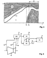
- FIG. 4 shows a device according to the invention.
- a measuring unit 11 To determine measured values 12 is to be transmitted via measuring lines 18 of sensor data with a system 19, for example a gas turbine 19, connected.
- An output of the measuring unit 11 with measured values 12 leads to a first computing unit 13 for determining a course of the Process variable P and to a second computing unit 15 for determining characteristic value ranges and regions.
- An exit from the first Computing unit 13 with data of the process variable course 14 leads to the second arithmetic unit 15 and on a display unit 17.
- An output with data on characteristic value ranges and regions 16 leads from the second arithmetic unit 15 to the display unit 17.
- the inventive The device is advantageously part of the process control system of the system implemented.
- the first arithmetic unit 13 stores past values of the process variable P. and of further process variables, so that the output data of the process variable course 14 both current and past values of process variables contain.
- the second arithmetic unit 15 determines the data on characteristic value ranges and regions 16 on the basis of predetermined reference values, reference trajectories and reference parameters. It fits the characteristic Value ranges and regions 16 as explained above dynamically the course the process variable P and the progression of further process variables the current state of the system.
- the second computing unit contains 15 preferably means for storing and processing further information, for example of reference courses and rules for determination based on characteristic value ranges of process variables a system state.
- the display unit 17 comprises means for displaying characteristic ones Value ranges with overlaid process variables, that is or several visual output devices such as screens or plotters to be superimposed Representation of the characteristic regions and the course of the at least one process variable P.
Landscapes
- Engineering & Computer Science (AREA)
- Human Computer Interaction (AREA)
- Physics & Mathematics (AREA)
- General Physics & Mathematics (AREA)
- Automation & Control Theory (AREA)
- Testing And Monitoring For Control Systems (AREA)
- Feedback Control In General (AREA)
- Selective Calling Equipment (AREA)
- User Interface Of Digital Computer (AREA)
Description
- Figur 1-3
- erfindungsgemässe Darstellungen; und
- Figur 4
- schematisch eine Struktur einer erfindungsgemässen Vorrichtung.
- 1
- erste Region
- 2
- erste Region
- 3
- zweite Region
- 4
- vierte Region
- 5
- dargestellter Prozessgrössenverlauf
- A
- unkritischer Verlauf
- B
- enges Toleranzband
- C
- Korrektur durch Bediener
- D
- Begrenzung durch Überlast
- E
- Begrenzung durch maximalen Entlastungsgradienten
- P
- Prozessgrösse
- t
- Zeitachse
- T0-T4
- Zeitpunkt
- TF
- Voraussagedauer
- 11
- Messeinheit MU
- 12
- Messwerte
- 13
- erste Recheneinheit R1
- 14
- Daten des Prozessgrössenverlaufs
- 15
- zweite Recheneinheit R2
- 16
- Daten zu charakteristischen Wertebereichen und Regionen
- 17
- Darstellungseinheit DU
- 18
- Messleitung
- 19
- System, Turbine
Claims (9)
- Verfahren zur Darstellung eines Betriebszustands eines Systems (19), insbesondere eines thermischen Kraftwerks oder Teilen davon bei dem ein zeitlicher Verlauf (5) mindestens einer Prozessgrösse (P) dargestellt wird, dadurch gekennzeichnet, dass charakteristische Wertebereiche der mindestens einen Prozessgrösse (P), welche unterschiedlichen Betriebszuständen des Systems (19) entsprechen, vorausberechnet werden, und dass Regionen (1,2,3,4) von zukünftigen und vergangenen charakteristischen Wertebereichen der Darstellung des zeitlichen Verlaufs (5) der mindestens einen Prozessgrösse überlagert werden.
- Verfahren gemäss Anspruch 1, dadurch gekennzeichnet, dass die vorausberechneten charakteristischen Wertebereiche anhand eines aktuellen Zustands des Systems (19) berechnet werden.
- Verfahren gemäss Anspruch 1, dadurch gekennzeichnet, dass die vorausberechneten charakteristischen Wertebereiche anhand gespeicherter Referenzverläufe des Systems (19) berechnet werden.
- Verfahren gemäss Anspruch 1, dadurch gekennzeichnet, dass der Verlauf (5) der Prozessgrösse sowie unterschiedliche Regionen (1,2,34) in der Darstellung durch unterschiedliche visuelle Merkmale wie Farbe, Muster, Helligkeit oder Blinken charakterisiert werden.
- Verfahren gemäss Anspruch 4, dadurch gekennzeichnet, dass, falls sich die mindestens eine Prozessgrösse (P) in einem bestimmten charakteristischen Wertebereich befindet, mindestens ein visuelles Merkmal des Verlaufs (5) der Prozessgrösse geändert wird.
- Verfahren gemäss Anspruch 4, dadurch gekennzeichnet, dass, falls sich die mindestens eine Prozessgrösse (P) in einem bestimmten charakteristischen Wertebereich befindet, mindestens ein visuelles Merkmal der entsprechenden Region (1,2,3,4) geändert wird.
- Vorrichtung zur Darstellung eines Betriebszustands eines Systems (19), insbesondere eines thermischen Kraftwerks oder Teilen davon, bestehend aus einer Messeinheit (11) zur Bestimmung von Messwerten (12), einer ersten Recheneinheit (13) zur Bestimmung eines Verlaufs von mindestens einer Prozessgrösse (P) anhand der Messwerte (12), und einer Anzeigeeinheit (17) zur Darstellung eines Verlaufs (5) der mindestens einen Prozessgrösse (P), dadurch gekennzeichnet, dass die Vorrichtung eine zweite Recheneinheit (15) zur Bestimmung von charakteristischen Wertebereichen und Regionen (1,2,3,4) anhand der Messwerte (12) und anhand von weiteren Informationen aufweist, und dass die Anzeigeeinheit (17) Mittel zur Darstellung von charakteristischen Regionen (1,2,3,4) mit einer überlagerten Darstellung des Verlaufs (5) der mindestens einen Prozessgrösse (P) aufweist.
- Vorrichtung gemäss Anspruch 7, dadurch gekennzeichnet, dass die charakteristischen Regionen (1,2,3,4) der Darstellung unterschiedliche visuelle Merkmale aufweisen.
- Vorrichtung gemäss Anspruch 7, dadurch gekennzeichnet, dass das System (19) ein Kraftwerk oder ein Teil davon, insbesondere eine Gas- oder Dampfturbine (19) ist.
Priority Applications (3)
| Application Number | Priority Date | Filing Date | Title |
|---|---|---|---|
| AT99810883T ATE282222T1 (de) | 1999-09-30 | 1999-09-30 | Darstellung eines betriebszustands eines systems |
| DE59911050T DE59911050D1 (de) | 1999-09-30 | 1999-09-30 | Darstellung eines Betriebszustands eines Systems |
| EP99810883A EP1089152B1 (de) | 1999-09-30 | 1999-09-30 | Darstellung eines Betriebszustands eines Systems |
Applications Claiming Priority (1)
| Application Number | Priority Date | Filing Date | Title |
|---|---|---|---|
| EP99810883A EP1089152B1 (de) | 1999-09-30 | 1999-09-30 | Darstellung eines Betriebszustands eines Systems |
Publications (2)
| Publication Number | Publication Date |
|---|---|
| EP1089152A1 EP1089152A1 (de) | 2001-04-04 |
| EP1089152B1 true EP1089152B1 (de) | 2004-11-10 |
Family
ID=8243057
Family Applications (1)
| Application Number | Title | Priority Date | Filing Date |
|---|---|---|---|
| EP99810883A Expired - Lifetime EP1089152B1 (de) | 1999-09-30 | 1999-09-30 | Darstellung eines Betriebszustands eines Systems |
Country Status (3)
| Country | Link |
|---|---|
| EP (1) | EP1089152B1 (de) |
| AT (1) | ATE282222T1 (de) |
| DE (1) | DE59911050D1 (de) |
Families Citing this family (2)
| Publication number | Priority date | Publication date | Assignee | Title |
|---|---|---|---|---|
| DE102015106199B4 (de) | 2015-04-22 | 2018-07-19 | Deutsches Zentrum für Luft- und Raumfahrt e.V. | Verfahren zur Bestimmung von Sollwerten eines technischen Systems, technisches System sowie Computerprogramm |
| DE102016225408A1 (de) * | 2016-12-19 | 2018-06-21 | Robert Bosch Gmbh | Fluidvorrichtung und Verfahren zur Überwachung einer Fluidvorrichtung |
Family Cites Families (6)
| Publication number | Priority date | Publication date | Assignee | Title |
|---|---|---|---|---|
| US4787053A (en) * | 1981-12-30 | 1988-11-22 | Semco Instruments, Inc. | Comprehensive engine monitor and recorder |
| JPS61245211A (ja) * | 1985-04-23 | 1986-10-31 | Mitsubishi Electric Corp | プロセス監視装置 |
| ATE117407T1 (de) * | 1991-04-16 | 1995-02-15 | Siemens Ag | Verfahren und vorrichtung zur überwachung des betriebszustandes einer dampfturbine. |
| DE19604803A1 (de) * | 1995-02-10 | 1996-10-10 | Meidensha Electric Mfg Co Ltd | Vorrichtung zur Systemzustandsüberwachung |
| DE19615960A1 (de) * | 1996-04-22 | 1997-10-23 | Siemens Ag | Verfahren und System zur Verarbeitung von Prozeßsignalen einer technischen Anlage |
| EP0915406B1 (de) * | 1997-11-10 | 2003-05-07 | ALSTOM (Switzerland) Ltd | Verfahren zur Überwachung des Versorgungssystems einer Gasturbine mit Mehrbrennersystem sowie Vorrichtung zur Durchführung des Verfahrens |
-
1999
- 1999-09-30 AT AT99810883T patent/ATE282222T1/de not_active IP Right Cessation
- 1999-09-30 EP EP99810883A patent/EP1089152B1/de not_active Expired - Lifetime
- 1999-09-30 DE DE59911050T patent/DE59911050D1/de not_active Expired - Lifetime
Also Published As
| Publication number | Publication date |
|---|---|
| ATE282222T1 (de) | 2004-11-15 |
| EP1089152A1 (de) | 2001-04-04 |
| DE59911050D1 (de) | 2004-12-16 |
Similar Documents
| Publication | Publication Date | Title |
|---|---|---|
| EP2145112B1 (de) | Einrichtung und verfahren zur störungsüberwachung | |
| DE69727044T2 (de) | Regelsystem zur überspannungsverhütung bei dynamischen kompressoren | |
| DE69921602T2 (de) | Auf einem multivariablen statistischen modell basierendes system zur darstellung des betriebs einer stranggiessanlage und detektion bevorstehender durchbrüche | |
| DE602004004496T2 (de) | Energieverbrauch in einem elektrischen Antrieb | |
| DE2635993C3 (de) | Brennstoffregelung für eine Gasturbinenanlage | |
| DE69306301T2 (de) | Regeleinrichtung und -verfahren für einen Kompressor treibenden Motor | |
| DE3120133C2 (de) | Vorrichtung zur Regelung und Steuerung einer Karde oder Krempel | |
| DE4108787A1 (de) | Verfahren und vorrichtung zum steuern der einer gasturbine zugefuehrten brennstoffmenge | |
| EP2463520A2 (de) | Verfahren zum Betrieb einer pitchgeregelten Windenergieanlage | |
| DE3937152A1 (de) | Verfahren zum optimierten betreiben zweier oder mehrerer kompressoren im parallel- oder reihenbetrieb | |
| DE2704098A1 (de) | Elektro-hydraulische dampfturbinen- regeleinrichtung | |
| DE102011050018A1 (de) | Pumpen-System | |
| EP1892597A1 (de) | Zustandsüberwachung von Maschinen und technischen Anlagen | |
| DE3445791C2 (de) | Wärmeleistungswächter zur Lieferung von Information über ein Dampfturbogeneratorsystem | |
| EP1195668A1 (de) | Prozessüberwachung zur Verschleisserkennung an Verzahnungswerkzeugen | |
| DE4126314C2 (de) | Verfahren und Vorrichtung zur Ermittlung von unregelmäßigen Zuständen in der Motorleistung durch Prüfen des momentanen Zustandes der Motorleistung | |
| DE19733454A1 (de) | Verfahren und Vorrichtung zur Erkennung und Korretur einer Faserorientierungs-Querprofil-Veränderung | |
| DE3415165C2 (de) | ||
| EP1089152B1 (de) | Darstellung eines Betriebszustands eines Systems | |
| EP3286375B1 (de) | Verfahren zur überwachung einer dichtungseinrichtung und dichtungseinrichtung | |
| DE3627300C2 (de) | ||
| EP0509347A1 (de) | Verfahren und Vorrichtung zur Überwachung des Betriebszustandes einer Dampfturbine | |
| DE3830805C2 (de) | ||
| EP3805884A1 (de) | Verfahren zur bestimmung und/oder klassifizierung eines bahnzustands einer warenbahn, computerprogrammprodukt, vorrichtung zur herstellung und industrielle anlage | |
| EP1260894B1 (de) | Verfahren zum Betrieb eines Antriebs und Vorrichtung |
Legal Events
| Date | Code | Title | Description |
|---|---|---|---|
| PUAI | Public reference made under article 153(3) epc to a published international application that has entered the european phase |
Free format text: ORIGINAL CODE: 0009012 |
|
| AK | Designated contracting states |
Kind code of ref document: A1 Designated state(s): AT BE CH CY DE DK ES FI FR GB GR IE IT LI LU MC NL PT SE |
|
| AX | Request for extension of the european patent |
Free format text: AL;LT;LV;MK;RO;SI |
|
| 17P | Request for examination filed |
Effective date: 20010824 |
|
| AKX | Designation fees paid |
Free format text: AT BE CH CY DE DK ES FI FR GB GR IE IT LI LU MC NL PT SE |
|
| RAP1 | Party data changed (applicant data changed or rights of an application transferred) |
Owner name: ABB SCHWEIZ AG |
|
| GRAP | Despatch of communication of intention to grant a patent |
Free format text: ORIGINAL CODE: EPIDOSNIGR1 |
|
| GRAS | Grant fee paid |
Free format text: ORIGINAL CODE: EPIDOSNIGR3 |
|
| GRAA | (expected) grant |
Free format text: ORIGINAL CODE: 0009210 |
|
| AK | Designated contracting states |
Kind code of ref document: B1 Designated state(s): AT BE CH CY DE DK ES FI FR GB GR IE IT LI LU MC NL PT SE |
|
| PG25 | Lapsed in a contracting state [announced via postgrant information from national office to epo] |
Ref country code: NL Free format text: LAPSE BECAUSE OF FAILURE TO SUBMIT A TRANSLATION OF THE DESCRIPTION OR TO PAY THE FEE WITHIN THE PRESCRIBED TIME-LIMIT Effective date: 20041110 Ref country code: IT Free format text: LAPSE BECAUSE OF FAILURE TO SUBMIT A TRANSLATION OF THE DESCRIPTION OR TO PAY THE FEE WITHIN THE PRESCRIBED TIME-LIMIT;WARNING: LAPSES OF ITALIAN PATENTS WITH EFFECTIVE DATE BEFORE 2007 MAY HAVE OCCURRED AT ANY TIME BEFORE 2007. THE CORRECT EFFECTIVE DATE MAY BE DIFFERENT FROM THE ONE RECORDED. Effective date: 20041110 Ref country code: IE Free format text: LAPSE BECAUSE OF FAILURE TO SUBMIT A TRANSLATION OF THE DESCRIPTION OR TO PAY THE FEE WITHIN THE PRESCRIBED TIME-LIMIT Effective date: 20041110 Ref country code: FI Free format text: LAPSE BECAUSE OF FAILURE TO SUBMIT A TRANSLATION OF THE DESCRIPTION OR TO PAY THE FEE WITHIN THE PRESCRIBED TIME-LIMIT Effective date: 20041110 |
|
| REG | Reference to a national code |
Ref country code: GB Ref legal event code: FG4D Free format text: NOT ENGLISH |
|
| REG | Reference to a national code |
Ref country code: CH Ref legal event code: EP |
|
| REG | Reference to a national code |
Ref country code: IE Ref legal event code: FG4D Free format text: GERMAN |
|
| REF | Corresponds to: |
Ref document number: 59911050 Country of ref document: DE Date of ref document: 20041216 Kind code of ref document: P |
|
| PG25 | Lapsed in a contracting state [announced via postgrant information from national office to epo] |
Ref country code: SE Free format text: LAPSE BECAUSE OF FAILURE TO SUBMIT A TRANSLATION OF THE DESCRIPTION OR TO PAY THE FEE WITHIN THE PRESCRIBED TIME-LIMIT Effective date: 20050210 Ref country code: GR Free format text: LAPSE BECAUSE OF FAILURE TO SUBMIT A TRANSLATION OF THE DESCRIPTION OR TO PAY THE FEE WITHIN THE PRESCRIBED TIME-LIMIT Effective date: 20050210 Ref country code: DK Free format text: LAPSE BECAUSE OF FAILURE TO SUBMIT A TRANSLATION OF THE DESCRIPTION OR TO PAY THE FEE WITHIN THE PRESCRIBED TIME-LIMIT Effective date: 20050210 |
|
| PG25 | Lapsed in a contracting state [announced via postgrant information from national office to epo] |
Ref country code: ES Free format text: LAPSE BECAUSE OF FAILURE TO SUBMIT A TRANSLATION OF THE DESCRIPTION OR TO PAY THE FEE WITHIN THE PRESCRIBED TIME-LIMIT Effective date: 20050221 |
|
| GBT | Gb: translation of ep patent filed (gb section 77(6)(a)/1977) |
Effective date: 20050221 |
|
| NLV1 | Nl: lapsed or annulled due to failure to fulfill the requirements of art. 29p and 29m of the patents act | ||
| REG | Reference to a national code |
Ref country code: IE Ref legal event code: FD4D |
|
| PLBE | No opposition filed within time limit |
Free format text: ORIGINAL CODE: 0009261 |
|
| STAA | Information on the status of an ep patent application or granted ep patent |
Free format text: STATUS: NO OPPOSITION FILED WITHIN TIME LIMIT |
|
| PG25 | Lapsed in a contracting state [announced via postgrant information from national office to epo] |
Ref country code: MC Free format text: LAPSE BECAUSE OF NON-PAYMENT OF DUE FEES Effective date: 20050930 Ref country code: LU Free format text: LAPSE BECAUSE OF NON-PAYMENT OF DUE FEES Effective date: 20050930 Ref country code: CY Free format text: LAPSE BECAUSE OF FAILURE TO SUBMIT A TRANSLATION OF THE DESCRIPTION OR TO PAY THE FEE WITHIN THE PRESCRIBED TIME-LIMIT Effective date: 20050930 Ref country code: BE Free format text: LAPSE BECAUSE OF NON-PAYMENT OF DUE FEES Effective date: 20050930 Ref country code: AT Free format text: LAPSE BECAUSE OF NON-PAYMENT OF DUE FEES Effective date: 20050930 |
|
| ET | Fr: translation filed | ||
| 26N | No opposition filed |
Effective date: 20050811 |
|
| BERE | Be: lapsed |
Owner name: *ABB SCHWEIZ A.G. Effective date: 20050930 |
|
| PG25 | Lapsed in a contracting state [announced via postgrant information from national office to epo] |
Ref country code: PT Free format text: LAPSE BECAUSE OF NON-PAYMENT OF DUE FEES Effective date: 20050410 |
|
| REG | Reference to a national code |
Ref country code: DE Ref legal event code: R082 Ref document number: 59911050 Country of ref document: DE |
|
| REG | Reference to a national code |
Ref country code: FR Ref legal event code: PLFP Year of fee payment: 18 |
|
| REG | Reference to a national code |
Ref country code: FR Ref legal event code: PLFP Year of fee payment: 19 |
|
| REG | Reference to a national code |
Ref country code: FR Ref legal event code: PLFP Year of fee payment: 20 |
|
| PGFP | Annual fee paid to national office [announced via postgrant information from national office to epo] |
Ref country code: FR Payment date: 20180924 Year of fee payment: 20 Ref country code: DE Payment date: 20180920 Year of fee payment: 20 |
|
| PGFP | Annual fee paid to national office [announced via postgrant information from national office to epo] |
Ref country code: GB Payment date: 20180919 Year of fee payment: 20 Ref country code: CH Payment date: 20180919 Year of fee payment: 20 |
|
| REG | Reference to a national code |
Ref country code: DE Ref legal event code: R071 Ref document number: 59911050 Country of ref document: DE |
|
| REG | Reference to a national code |
Ref country code: CH Ref legal event code: PL |
|
| REG | Reference to a national code |
Ref country code: GB Ref legal event code: PE20 Expiry date: 20190929 |
|
| PG25 | Lapsed in a contracting state [announced via postgrant information from national office to epo] |
Ref country code: GB Free format text: LAPSE BECAUSE OF EXPIRATION OF PROTECTION Effective date: 20190929 |