EP1089161A2 - Objektverarbeitungsgerät und Verfahren zur Modifikation des Objektsattributes - Google Patents
Objektverarbeitungsgerät und Verfahren zur Modifikation des Objektsattributes Download PDFInfo
- Publication number
- EP1089161A2 EP1089161A2 EP00121114A EP00121114A EP1089161A2 EP 1089161 A2 EP1089161 A2 EP 1089161A2 EP 00121114 A EP00121114 A EP 00121114A EP 00121114 A EP00121114 A EP 00121114A EP 1089161 A2 EP1089161 A2 EP 1089161A2
- Authority
- EP
- European Patent Office
- Prior art keywords
- image
- information
- icon
- control information
- displayed
- Prior art date
- Legal status (The legal status is an assumption and is not a legal conclusion. Google has not performed a legal analysis and makes no representation as to the accuracy of the status listed.)
- Withdrawn
Links
Images













Classifications
-
- G—PHYSICS
- G06—COMPUTING OR CALCULATING; COUNTING
- G06F—ELECTRIC DIGITAL DATA PROCESSING
- G06F3/00—Input arrangements for transferring data to be processed into a form capable of being handled by the computer; Output arrangements for transferring data from processing unit to output unit, e.g. interface arrangements
- G06F3/01—Input arrangements or combined input and output arrangements for interaction between user and computer
- G06F3/048—Interaction techniques based on graphical user interfaces [GUI]
- G06F3/0484—Interaction techniques based on graphical user interfaces [GUI] for the control of specific functions or operations, e.g. selecting or manipulating an object, an image or a displayed text element, setting a parameter value or selecting a range
- G06F3/04845—Interaction techniques based on graphical user interfaces [GUI] for the control of specific functions or operations, e.g. selecting or manipulating an object, an image or a displayed text element, setting a parameter value or selecting a range for image manipulation, e.g. dragging, rotation, expansion or change of colour
-
- G—PHYSICS
- G06—COMPUTING OR CALCULATING; COUNTING
- G06T—IMAGE DATA PROCESSING OR GENERATION, IN GENERAL
- G06T7/00—Image analysis
-
- G—PHYSICS
- G06—COMPUTING OR CALCULATING; COUNTING
- G06F—ELECTRIC DIGITAL DATA PROCESSING
- G06F3/00—Input arrangements for transferring data to be processed into a form capable of being handled by the computer; Output arrangements for transferring data from processing unit to output unit, e.g. interface arrangements
- G06F3/01—Input arrangements or combined input and output arrangements for interaction between user and computer
- G06F3/048—Interaction techniques based on graphical user interfaces [GUI]
- G06F3/0484—Interaction techniques based on graphical user interfaces [GUI] for the control of specific functions or operations, e.g. selecting or manipulating an object, an image or a displayed text element, setting a parameter value or selecting a range
- G06F3/0486—Drag-and-drop
-
- H—ELECTRICITY
- H04—ELECTRIC COMMUNICATION TECHNIQUE
- H04N—PICTORIAL COMMUNICATION, e.g. TELEVISION
- H04N1/00—Scanning, transmission or reproduction of documents or the like, e.g. facsimile transmission; Details thereof
- H04N1/00127—Connection or combination of a still picture apparatus with another apparatus, e.g. for storage, processing or transmission of still picture signals or of information associated with a still picture
- H04N1/00132—Connection or combination of a still picture apparatus with another apparatus, e.g. for storage, processing or transmission of still picture signals or of information associated with a still picture in a digital photofinishing system, i.e. a system where digital photographic images undergo typical photofinishing processing, e.g. printing ordering
-
- H—ELECTRICITY
- H04—ELECTRIC COMMUNICATION TECHNIQUE
- H04N—PICTORIAL COMMUNICATION, e.g. TELEVISION
- H04N1/00—Scanning, transmission or reproduction of documents or the like, e.g. facsimile transmission; Details thereof
- H04N1/00127—Connection or combination of a still picture apparatus with another apparatus, e.g. for storage, processing or transmission of still picture signals or of information associated with a still picture
- H04N1/00132—Connection or combination of a still picture apparatus with another apparatus, e.g. for storage, processing or transmission of still picture signals or of information associated with a still picture in a digital photofinishing system, i.e. a system where digital photographic images undergo typical photofinishing processing, e.g. printing ordering
- H04N1/00137—Transmission
-
- H—ELECTRICITY
- H04—ELECTRIC COMMUNICATION TECHNIQUE
- H04N—PICTORIAL COMMUNICATION, e.g. TELEVISION
- H04N1/00—Scanning, transmission or reproduction of documents or the like, e.g. facsimile transmission; Details thereof
- H04N1/00127—Connection or combination of a still picture apparatus with another apparatus, e.g. for storage, processing or transmission of still picture signals or of information associated with a still picture
- H04N1/00132—Connection or combination of a still picture apparatus with another apparatus, e.g. for storage, processing or transmission of still picture signals or of information associated with a still picture in a digital photofinishing system, i.e. a system where digital photographic images undergo typical photofinishing processing, e.g. printing ordering
- H04N1/00143—Ordering
-
- H—ELECTRICITY
- H04—ELECTRIC COMMUNICATION TECHNIQUE
- H04N—PICTORIAL COMMUNICATION, e.g. TELEVISION
- H04N1/00—Scanning, transmission or reproduction of documents or the like, e.g. facsimile transmission; Details thereof
- H04N1/00127—Connection or combination of a still picture apparatus with another apparatus, e.g. for storage, processing or transmission of still picture signals or of information associated with a still picture
- H04N1/00132—Connection or combination of a still picture apparatus with another apparatus, e.g. for storage, processing or transmission of still picture signals or of information associated with a still picture in a digital photofinishing system, i.e. a system where digital photographic images undergo typical photofinishing processing, e.g. printing ordering
- H04N1/00161—Viewing or previewing
-
- H—ELECTRICITY
- H04—ELECTRIC COMMUNICATION TECHNIQUE
- H04N—PICTORIAL COMMUNICATION, e.g. TELEVISION
- H04N1/00—Scanning, transmission or reproduction of documents or the like, e.g. facsimile transmission; Details thereof
- H04N1/00127—Connection or combination of a still picture apparatus with another apparatus, e.g. for storage, processing or transmission of still picture signals or of information associated with a still picture
- H04N1/00132—Connection or combination of a still picture apparatus with another apparatus, e.g. for storage, processing or transmission of still picture signals or of information associated with a still picture in a digital photofinishing system, i.e. a system where digital photographic images undergo typical photofinishing processing, e.g. printing ordering
- H04N1/00167—Processing or editing
-
- H—ELECTRICITY
- H04—ELECTRIC COMMUNICATION TECHNIQUE
- H04N—PICTORIAL COMMUNICATION, e.g. TELEVISION
- H04N1/00—Scanning, transmission or reproduction of documents or the like, e.g. facsimile transmission; Details thereof
- H04N1/0035—User-machine interface; Control console
- H04N1/00405—Output means
- H04N1/00408—Display of information to the user, e.g. menus
- H04N1/00411—Display of information to the user, e.g. menus the display also being used for user input, e.g. touch screen
-
- H—ELECTRICITY
- H04—ELECTRIC COMMUNICATION TECHNIQUE
- H04N—PICTORIAL COMMUNICATION, e.g. TELEVISION
- H04N1/00—Scanning, transmission or reproduction of documents or the like, e.g. facsimile transmission; Details thereof
- H04N1/0035—User-machine interface; Control console
- H04N1/00405—Output means
- H04N1/00408—Display of information to the user, e.g. menus
- H04N1/00413—Display of information to the user, e.g. menus using menus, i.e. presenting the user with a plurality of selectable options
-
- H—ELECTRICITY
- H04—ELECTRIC COMMUNICATION TECHNIQUE
- H04N—PICTORIAL COMMUNICATION, e.g. TELEVISION
- H04N1/00—Scanning, transmission or reproduction of documents or the like, e.g. facsimile transmission; Details thereof
- H04N1/0035—User-machine interface; Control console
- H04N1/00405—Output means
- H04N1/00408—Display of information to the user, e.g. menus
- H04N1/00413—Display of information to the user, e.g. menus using menus, i.e. presenting the user with a plurality of selectable options
- H04N1/00416—Multi-level menus
-
- H—ELECTRICITY
- H04—ELECTRIC COMMUNICATION TECHNIQUE
- H04N—PICTORIAL COMMUNICATION, e.g. TELEVISION
- H04N1/00—Scanning, transmission or reproduction of documents or the like, e.g. facsimile transmission; Details thereof
- H04N1/0035—User-machine interface; Control console
- H04N1/00405—Output means
- H04N1/00408—Display of information to the user, e.g. menus
- H04N1/00413—Display of information to the user, e.g. menus using menus, i.e. presenting the user with a plurality of selectable options
- H04N1/00416—Multi-level menus
- H04N1/00419—Arrangements for navigating between pages or parts of the menu
- H04N1/00424—Arrangements for navigating between pages or parts of the menu using a list of graphical elements, e.g. icons or icon bar
-
- H—ELECTRICITY
- H04—ELECTRIC COMMUNICATION TECHNIQUE
- H04N—PICTORIAL COMMUNICATION, e.g. TELEVISION
- H04N1/00—Scanning, transmission or reproduction of documents or the like, e.g. facsimile transmission; Details thereof
- H04N1/0035—User-machine interface; Control console
- H04N1/00405—Output means
- H04N1/00408—Display of information to the user, e.g. menus
- H04N1/0044—Display of information to the user, e.g. menus for image preview or review, e.g. to help the user position a sheet
-
- H—ELECTRICITY
- H04—ELECTRIC COMMUNICATION TECHNIQUE
- H04N—PICTORIAL COMMUNICATION, e.g. TELEVISION
- H04N1/00—Scanning, transmission or reproduction of documents or the like, e.g. facsimile transmission; Details thereof
- H04N1/0035—User-machine interface; Control console
- H04N1/00405—Output means
- H04N1/00408—Display of information to the user, e.g. menus
- H04N1/00466—Display of information to the user, e.g. menus displaying finishing information, e.g. position of punch holes or staple or orientation references
-
- H—ELECTRICITY
- H04—ELECTRIC COMMUNICATION TECHNIQUE
- H04N—PICTORIAL COMMUNICATION, e.g. TELEVISION
- H04N1/00—Scanning, transmission or reproduction of documents or the like, e.g. facsimile transmission; Details thereof
- H04N1/0035—User-machine interface; Control console
- H04N1/00405—Output means
- H04N1/00408—Display of information to the user, e.g. menus
- H04N1/00469—Display of information to the user, e.g. menus with enlargement of a selected area of the displayed information
-
- H—ELECTRICITY
- H04—ELECTRIC COMMUNICATION TECHNIQUE
- H04N—PICTORIAL COMMUNICATION, e.g. TELEVISION
- H04N1/00—Scanning, transmission or reproduction of documents or the like, e.g. facsimile transmission; Details thereof
- H04N1/0035—User-machine interface; Control console
- H04N1/00405—Output means
- H04N1/00482—Output means outputting a plurality of job set-up options, e.g. number of copies, paper size or resolution
-
- H—ELECTRICITY
- H04—ELECTRIC COMMUNICATION TECHNIQUE
- H04N—PICTORIAL COMMUNICATION, e.g. TELEVISION
- H04N2101/00—Still video cameras
Definitions
- the present invention relates to object processing apparatus and object attribute changing methods, and more particularly to such apparatus and methods which display and/or process image objects such as photographs, illustrations or handwritten characters.
- Such electronic products have the advantages that their reproductions are easy to obtain, edit and process compared to substantial products such as prints. However, they vary in kind and use, and their contents cannot be understood without using predetermined devices. Thus, management of those products is difficult.
- characters files mainly containing image data such as photographs, illustrations and/or handwritten characters
- sound files files mainly containing sound data such as musical sound files and/or voice data files
- character files are especially difficult to manage compared to files mainly containing character data such as document files, spreadsheet files and/or database files (hereinafter referred to as "character files”.
- the document files, image files and sound files can each be defined as "a collection of electronic data having a composition recognizable by an OS file system". According to an object-oriented concept, this definition is an unsubstantial "concept” 1) .
- a "thing” to which a concept is applied is a substantial object (also referred to as an "instance”).
- a file recognized by the OS file system is a concept and a file actually present in the recording medium is an object as an actually erasable, processable or reproducable "thing".
- the term "objects" which include the files will be used.
- Note 1) the concept is defined herein as a person's comprehension or way of thinking produced by his or her conscious activity. A like term is "idea” defined herein as implying a person's personal comprehension or way of thinking whereas the concept is had equally by a plurality of persons. Thus, they are basically different from each other.
- image objects Objects mainly including image data (hereinafter referred to as "image objects") are not limited to the image files illustrated above. For example, they include the ones related to other objects (so-called related objects) and collections of data (data arrays on a memory and/or image data stored in fields of a database) which cannot be recognized by the OS file system and hence not handled as files.
- Objects which are especially difficult to manage and process include the above-mentioned image objects as well as sound objects which contain musical sound files created by composition software and voice data files which contain digitally recorded animals' voices. Problems such as were mentioned above are likewise present not only in those non-character objects, but also in the character objects.
- an object processing apparatus comprising:
- the control information is added to the object to thereby change a display state and/or attributes of the object easily.
- the display control means may comprise means for displaying on the display device a plurality of icons each allocated different control information.
- the control information adding means may relate a desired one of the plurality of icons to the object on the display screen of the display device to thereby add to the object control information corresponding to the desired icon.
- the control information adding means may relate the icon to the object by dragging and dropping the icon onto the object.
- the icon may correspond to a plurality of pieces of control information.
- the control information adding means may select one from the plurality of pieces of control information at a position where the icon is dropped on to the object and then adds the selected piece of control information to the object.
- the control information may specify a type or a mode in which the object is displayed.
- the control information may specify the conditions to enable the object to be displayed on said display device.
- the control information comprises information on a link with another object.
- the control information may comprise information on a category classification of the object.
- the control information may comprise information on a different image displayed along with the object.
- the present invention also provides an object attribute changing method comprising the steps of:
- the reason for using the electronic still camera as an example is as follows.
- many of the electronic still cameras, especially with a monitoring display device are capable of reproducing a recorded image file (image object) on the spot, and the user is able to perform simple processing on the image object (a change of its attributes) while viewing the reproduced image.
- the electronic still cameras having the functions of producing, displaying and processing image files are each considered to be a kind of an image object processing device.
- FIG. 1 is a perspective back view of the electronic still camera 1, which although not limited especially, comprises a body 2 and a camera device 3 attached rotatably to the body 2.
- a photographing lens (not shown) exposed externally is attached to the front (in FIG. 1, back) of the camera device 3.
- An image sensor (CCD) hidden within the camera device 3 is attached to a back of the photographing lens.
- the image sensor converts an object image picked up by the photographing lens to a video signal and outputs a corresponding periodical image signal (frame image signal) of high resolution depending on the number of pixels of the object image.
- a touch-paneled flat display unit 4 is attached to the back of the body 2 to display an image (a through image for adjusting its compositional arrangement or a recorded captured image).
- various operation keys for example, a shutter key 5 which fixes the exposure when half depressed and which captures the image when depressed completely; a plus key 6 which selects a plus direction; a minus key 7 which selects a minus direction; a menu key 8 which performs system setting operations in various respects (such as the minuteness of a recorded image, turning on/off the auto focus, a time required for picking up an image of an animation, etc.); a power source switch 9 for turning on/off a power supply of the camera 1; a display key 10 which causes various overlapping information to be displayed on the display device 4; a record mode key 11 which selects one of record modes for ordinary image pickup and panoramic image pickup; a self timer key 12 which turns on/off a self timer function; and a strobe mode key 13 which turns on an image (a through image for adjusting
- FIG. 2 is a block diagram of the electronic still camera 1, which comprises an image producing system 15 which produces an image signal indicative of an object, a temporary storage system 16 which temporarily stores the image signal for reproducing or playing and processing purposes, a long-term storage system 17 which stores a captured image for a long time, an image display system 18 which displays a reproduced image or an image for confirming its compositional arrangement in the image pickup, a communication system 19 which outputs to the outside the image signal stored in the temporarily storage system 16 or in the long-term storage system 17 and which receives such image signal from the outside, a compressing/expanding system 20 which compresses the image signal when stored in the long-term storage system 17 and expands the image signal read out from the long-term storage system 17, a control system 21 which controls the whole operation of the camera 1, and a data transfer system 22.
- an image producing system 15 which produces an image signal indicative of an object
- a temporary storage system 16 which temporarily stores the image signal for reproducing or playing and processing purposes
- a long-term storage system 17
- the image producing system 15 converts an object image to an electric signal with the image sensor, produces a periodical image signal from the electric signal, and outputs it.
- the image producing system 15 is illustrated as producing a color image signal, it may produce a monochromatic image signal.
- the image producing system 15 comprises an optical system 29 which comprises a photographing lens and an iris mechanism, an image sensor (hereinafter referred to as a CCD) 30 which converts light from the object which has passed through the optical system 29 to an electric signal, and which outputs a corresponding frame image signal of a predetermined cycle, a driver 31 which drives the CCD 30, a timing generator 32 which generates various timing signals including a signal which controls the image pickup time (electronic shutter time) of the CCD 30, a sample and hold circuit 33 which samples a frame image signal output from the CCD 30 and eliminates noise, an analog-to-digital converter 34 which converts the noise-free frame image signal from the sample and hold circuit 33 to a digital signal, and a color processing circuit 35 which produces a brightness/color-difference synthesis signal (which can be referred to as a "YUV signal” hereinafter) or a color image signal, using an output from the analog-to-digital converter 34.
- a CCD image sensor
- the temporary storage system 16 comprises a buffer memory 37 having a predetermined storage capacity composed of a rewritable storage medium (for example, a semiconductor memory such as a DRAM or SRAM), which has a buffer area of at least a size or storage capacity enough to develop the image signal fetched from the image producing system 15, the communication system or the long-term storage system 17 through the data transfer system 22. More particularly, the buffer area has a size substantially capable of temporarily storing at least one still image. When the camera is capable of picking up/reproducing the image of an animation, the buffer area has substantially a size capable of temporarily storing a plurality of images which compose the animation. The still picture buffer area may overlap with, or independent of, the animation buffer area.
- the buffer memory 37 comprises a work area for image processing which is used by the control system 21 when image processing to be described later is performed.
- the long-term storage system 17 comprises a rewritable volatile storage medium, for example, a flash memory 39, which has a capacity enough to store scores-hundreds of image files (generally, in the case of the still picture, compressed image files of the JPEG type) of a predetermined type compressed in the compressing/expanding system 20.
- the flash memory 39 may be of a removable type, for example, a card type.
- the image display system 18 reproduces and displays an image signal (a so-called through image) output at predetermined cycles from the image producing system 15 for confirming the compositional arrangement of the image, and reproduces and displays an image recorded in the flash memory 39 or an image received from outside through the communication system 19.
- the image display system 18 comprises a digital video encoder 42 which converts a size of a reproduced image to a display size, a color liquid crystal display 43 which displays an output from the digital video encoder 42 on the display screen, a touch panel 44 which senses coordinates of a position touched on the display screen of the display 43, a touch panel I/F (interface) 45 which converts an output signal from the touch panel 44 to a predetermined form, which is then output to the control panel 21.
- the display 42 and touch panel 44 compose the touch-paneled flat display device 4 of FIG. 1.
- the communication system 19 comprises a communication unit 46 which sends/receives data to/from external information processing devices through optical, radio or cable communication.
- the composition of the communication unit 46 depends on its communication system. For example, when it is connected to an external information processing terminal via a public communication telephone line, it should have a composition similar to that of a telephone terminal with a modem.
- the compressing/expanding system 20 compresses in a predetermined format an image signal stored in the buffer memory 37 and expands in the format a compressed image file stored in the flash memory 39.
- the standards of compression/expansion format in the case of a still image are JPEG (Joint Photographic Experts Group) and an extender of an image file according to the standards is "jpg". It is to be noted that when an extender format compatible with JPEG is employed, an extender other than the jpg can be used, but both are not discriminated from each other in the following description.
- the control system 21 comprises a CPU 40 which executes a predetermined control program to control the whole operation of the camera 1, and a key-in unit 40 which responds to operation of a respective one of the various keys including the shutter key 5 (5-14 of FIG. 1) to produce a required key operation signal and to provide this signal to CPU 40.
- the data transfer system 22 comprises a video transfer circuit 36 which compromises flows of data among the respective systems and buses (data bus, address bus and control line) 47 which connect the respective systems.
- FIG. 3 is a flowchart indicative of an outline of a whole control program executed by the control system 21.
- the control system 21 performs an initializing operation including checking the operation of the camera.
- step S2 it determines a set operational mode of the record/play key 14 (whether the key 14 is in the record mode or play mode) and performs a process (a record mode process in step S3 or a play mode process in step S4) branching depending on a result of the determination. It repeats those steps.
- a set operational mode of the record/play key 14 whether the key 14 is in the record mode or play mode
- a process a record mode process in step S3 or a play mode process in step S4 branching depending on a result of the determination. It repeats those steps.
- FIG. 4 is a flowchart of a program indicative of a record mode process.
- the control system 21 repeats reading an image signal or a CCD image from the image producing system 15 in step S11 and displaying the image signal on the image display system 18 in step S12 until the shutter key 5 is depressed half.
- a corresponding through image is updated and displayed at predetermined intervals of time on the liquid crystal display 43 of the image display system 18 for compositional arrangement thereof.
- step S13 when the half depression of the shutter key 5 is sensed, the iris of the optical system 29 is fixed at a degree of exposure depending on the brightness of the object at that time.
- step S15 when the complete depression of the shutter key is sensed, in step S16 the CCD image at that time is compressed and stored in the flash memory 39, which is referred to as image capture and the recorded image is referred to as a captured image, which is the one compressed according to JPEG by the compressing/expanding system 20.
- An image file (image object) containing this image has an extender "jpg" and a title of a string of not more than 8 characters.
- step S17 it is determined whether a stamping process is effective.
- the stamping process comprises adding various information to the captured image to facilitate management and processing of the captured image. If the stamping process is not effective, the control returns to step S2 of FIG. 3. If stamping process is effective, the control passes to step S18 to execute a stamping process program. It is to be noted that the stamping process may be effective at all times or selected in the system setting mode whose description is omitted.
- FIG. 5 is a flowchart of a program for the stamping process.
- this program starts, first, in step S21 a predetermined operation picture 50 is displayed on the liquid crystal display 43.
- FIG. 6 illustrates the operation picture 50 which comprises a first area 52 which displays an image object (captured image) 51, a second area 53 which displays various operation icons (stamps), and a third area 54 which displays information on each of the operation icons and receives information input by the user.
- a graphic keyboard area and/or handwritten character input area are displayed in a pop-up manner on the operation picture 50 to facilitate input of information by the user.
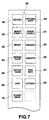
- the second area 53 is adapted to be scrolled up and down by operating upper and lower triangular-marked buttons 55, 56 or intermediate button 57 provided along a right-hand edge of the operation picture 50 to enable the user to select one of various operation icons of FIG. 7, which include, for example, a secret (SECRET) icon 58, a special effect (SPCIAL EFCT) icon 59, an image conversion (IMAGE CONV) 1 icon 60, an image conversion (IMAGE CONV) 2 icon 61, a mosaic (MSAIC) icon 62, a gradation (GRADAT) icon 63, a browse-date specifying (BRWSE DATE) icon 64, a signal arrival unnotification specifying (UNNOTF) icon 65, an effective term specifying (EFCTIV TERM) icon 66, a position information (POS INFO) icon 67, a link specifying (LINK) icon 68, a category classifying (CATGRY) icon 69, and a stamp mark (STAMP MARK) icon 70.
- a desired icon is selected by touching a finger or a pen tip on the icon.
- An operation icon is related with an image object by dragging and dropping the icon onto the image object 51 (for example, by selecting and moving the icon as selected as shown by an outline arrow in FIG. 6, and then dropping it onto the image object 51).
- the icon may be related to the image object by selecting the icon and then touching it with a finger or a pen tip.
- step S32 the termination of the looping process (in step S32) (for example, a touch on an end button (not shown) provided on the operation picture 50) is detected, the control returns to step S2 of FIG. 3.
- step S22 When selection of any operation icon is detected in the looping process, a corresponding process is performed. For example, when selection of the secret icon is detected in step S22, the control passes to step S23 to perform a secret process. When selection of the special effect icon 59 is detected in step S24, the control passes to step S25 to perform a special effect process. When selection of the image conversion 1 icon 60 is detected in step S26, the control passes to step S27 to perform an image conversion 1 process, ...(The description herein is omitted).... When selection of the stamp mark icon 70 is detected in step S28, control passes to step S29 to perform a stamp mark process.
- step S30 the control returns to the looping process to pass to step S30, where it is determined whether the operation icon is dragged and dropped onto the displayed image object 51. If it is, the control passes to step S31, where "stamp information", which will be described later, produced by the process performed when the dragged icon was selected (for example, the process performed in step S23 when the dragged icon includes the secret icon 58; the process performed in step S25 when the dragged icon includes the special effect icon 59) is added to the displayed image object 51 to update same, and the resulting object is then compressed and stored in the flash memory 39 (by overwriting or along with a new file name). The control then passes to step S32 to detect termination of the process. If no operation icon is dragged, the control directly passes to step S32.
- stamp information which will be described later
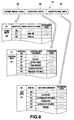
- FIG. 8 shows a data composition of the stamp information 71, which comprises, for example, three fields; that is, a first or head field 72 for storage of a stamp image code, a second or intermediate field 73 for storage of control information, and a third or last field 74 for storage of additional information.
- the first field 72 comprises an identification section, an image number section, an image data file name section and an extension code section.
- the second field 73 comprises an identification section, a control number section, a control information content section and an extension code section.
- the third field 74 comprises an identification section, an additional number section, an additional information content section and an extension code section.
- Information data for distinguishing the fields for example, "00", "01", and "02" are stored in the respective identification sections of the first, second and third fields 72, 73, and 74, respectively, which are combined with the following two-digit information data (information on the image number section in the case of the first field 72, information on the control number section in the case of the second field 73 and information on the additional number section in the case of the third field 74) to specify the contents of each field.
- the contents of data settable in each field are prepared in the form of a table.
- nothing or no image data file name is stored in a first row of a table corresponding to the first field 72, and a convenient image data file name "aaaa.gif" is stored in a second row.
- a convenient image data file name "bbbb.gif" is stored in a third row.
- the extender code section of each of the first, second and third fields 72, 73 and 74 is not used.
- the respective information storage sections (image data file name section, control information section and additional information section) of the tables corresponding to the first, second and third fields 72, 73 and 74 are referred to in the respective steps S23, S25, S27, ..., S29 of FIG. 5 executed in response to selection of the corresponding operation icons 58-70 (FIG. 7).
- step S23 when the secret process (step S23) is executed, the second row ("0101") of the second field 73 is referred to. If the special effect process (step S25) is executed, the third row ("0102") of the second field 73 is referred to. If the image conversion 1 process (step S27) is executed, the fifth row ("0104") of the second field 73 is referred to.
- FIG. 9 illustrates pictures displayed on the second and third areas of 53 and 54 during execution of the secret process.
- the secret icon 58 in the second area 53 is a selected state and the third area 54 is in a displayed state corresponding to the secret process, which includes hiding the image object 51 displayed on the operation picture 50 (FIG. 6) where a password is required to read the image object 51.
- secret attributes are required to be added to the image object 51 and any password information to release the image object 51 from the secret attributes is required to be added to the image object 51.
- a text box 81 in the third area 54 is used to input the password thereto.
- the user touches the text box 81, for example, with a pen tip to display a required text input support means (for example, a graphic keyboard area or a handwritten character input area) in a pop-up manner, and then inputs any password of digits of characters/symbols.
- a required text input support means for example, a graphic keyboard area or a handwritten character input area
- the secret attributes and password information are stored in the appropriate fields for the FIG. 8 stamp information. Then, by dragging and dropping the secret icon in the second area 58 onto the image object 51, the stamp information including the secret attributes and password information is synthesized with, or added to, the object 51.
- a preset plurality of secret stamps each for a respective password may be synthesized with, or added to, the corresponding image objects.
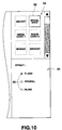
- FIG. 10 illustrates pictures displayed in the second and third areas 53 and 54 during execution of the special effect process.
- the special effect icon 59 in the second area 53 is in a selected state and the third area 54 is in a displayed state corresponding to the special effect process.
- the special effect process comprises giving various special effects to the image object 51 displayed on the operation picture 50 (FIG. 6).
- desired ones are selectable from among well-known image processing techniques such as, for example, slide, flash and spiral effects.
- Three option buttons 82 in the third area 54 are used to specify the respective kinds of special effects (flash, spiral and blind effects indicated for convenience sake in FIG. 10).
- a control appropriate for the user to input information representing a degree of the special effect may be disposed in the third area 54.
- the information representing the degree of the special effect (and when the control to input information representing the degree of the special effect is disposed, the information selected by the control) is stored in the appropriate field for the FIG. 8 stamp information.
- the FIG. 8 stamp information including the information representing the degree of the special effect (and when the control to input information representing the degree of the special effect is disposed, the information selected by the control) is synthesized with the image object 51.
- a desired one may be selected from a plurality of stamps each created for a respective one of a plurality of special effects, dragged and dropped onto the image object 51.
- Image conversion 1 process (step S27 of FIG. 5):
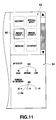
- FIG. 11 illustrates pictures displayed in the second and third areas 53 and 54 during execution of the image conversion 1 process.
- an image conversion 1 icon 60 in the second area 53 is in a selected state and the third area 54 is in a displayed state corresponding to the image conversion 1 process.
- the image conversion 1 process includes applying a division rearranging puzzle to the image object 51 displayed on the operation picture 50 (FIG. 6) (the puzzle includes rearranging in specified order a random array of divisions into which a picture is divided).
- Three option buttons 83 provided at upper positions in the third area 54 are each used to specify a degree of difficulty of the puzzle.
- Four option buttons 84 provided at lower positions are each used to specify the number of divisions. The user touches one of the option buttons 83, for example, with a pen tip to select a degree of difficulty of the puzzle, and touches one of the option buttons 84 to select the number of divisions.
- FIG. 8 stamp information comprising the information on the degree of difficulty and on the number of divisions is synthesized with the image object 51.
- Image conversion 2 process (omitted in FIG. 5):
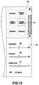
- FIG. 12 illustrates pictures displayed on the second and third areas 53 and 54 during execution of the image conversion 2 process.
- the image conversion 2 icon 61 in the second area 53 is in a selected state and the third area 54 is in a displayed state corresponding to the image conversion 2 process, which comprises changing to another a hue of the image object 51 displayed on the operation picture 50 (FIG. 6) and changing the color of the image object 51 to sepia.
- Three slide controls 85, 86 and 87 provided in the third area 54 are used to specify brightness, contrast and gamma values, respectively.
- a check box 88 provided at the lowest position is used to specify a change of the color of the image object 51 to sepia.
- the user specifies, for example with a pen tip, any particular one of the slide controls 85-87 to specify the brightness, contrast and gamma value or select and check off the check box 88 to specify a change of the color of the image object 51 to sepia.
- the information on a change of the hue of the image object 51 or on a change of the color of the image object 51 to sepia is stored in the appropriate field for the FIG. 8 stamp information. Then, by dragging and dropping the image conversion 2 icon 61 in the second area 58 onto the image object 51, the FIG. 8 stamp information comprising the information on the change of the hue of the image object 51 and on the change of the color of the image object 51 to sepia is synthesized with the image object 51.
- FIG. 13 illustrates pictures displayed in the second area 53 and third area 54 during execution of the mosaic process.
- a mosaic icon 62 in the second area 53 is in a selected state whereas the third area 54 is in a displayed state corresponding to the mosaic process, which comprises covering with a mosaic pattern any portion of the image object 51 displayed on the operation picture 50 (FIG. 6).
- the mosaic process information on the coordinates of a position of the portion of the image object 51 covered with the mosaic pattern and information representing a strength of the mosaic pattern are required to be inputted.
- Two button controls 89 and 90 provided in the third area 54 are each used to input coordinate information and three option buttons 91 provided in the third area 54 are each used to specify a strength of the mosaic pattern.
- the user sequentially touches with the pen tip the button control 89 indicated as a start point, coordinates (Xs, Ys) of the start point of the image object 51, the button control 90 indicated as an end point, and the coordinates (Xe, Ye) of the end point of the image object 51.
- the coordinates (Xs, Ys) and (Xe, Ye) of the start and end points are read and displayed on the respective sides of the button controls 89 and 90.
- a range indicated by a broken line rectangle and containing the two opposite corner coordinates (Xs, Ys) and (Xe, Ye) in FIG. 13B is recognized as a portion of the image object 51 to be covered with the mosaic pattern.
- the user selects one of the option buttons 91 as requested to specify a mosaic intensity.
- the information on the portion of the image object to be covered with the mosaic pattern and on the strength of the mosaic pattern is stored in the appropriate fields for the FIG. 8 stamp information.
- the FIG. 8 stamp information comprising the information on the image object portion to be covered with the mosaic pattern and the information on the mosaic intensity is synthesized with the image object 51.
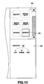
- FIG. 14 illustrates pictures displayed in the second and third areas 53 and 54 during execution of the gradation process.
- a gradation icon 63 in the second area 53 is in a selected state and the third area 54 is in a displayed state corresponding to the gradation process, which comprises performing the gradation process on the image object 51 displayed on the operation picture 50 (FIG. 6).
- buttons 92 provided in the third area 54 are each used to specify a degree of the gradation.
- information representing the degree of the gradation is stored in the appropriate field for the FIG. 8 stamp information.
- the FIG. 8 stamp information comprising the information representing the degree of the gradation is synthesized with the image object 51.
- FIG. 15 illustrates pictures displayed in the second and third areas 53 and 54 during execution of this process.
- a browse date specifying icon 64 in the second area 53 is in a selected state and the third area 54 is in a displayed state corresponding to the browse date specifying process, which comprises specifying a date on and after which the image object 51 displayed on the operation picture 50 (FIG. 6) is browsable (it is not browsable before the date).
- required text input support means for example, a graphic keyboard area or handwritten character input area
- FIG. 8 stamp information comprising the information on the browse date and time is synthesized with the image object 51.
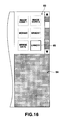
- FIG. 16 illustrates pictures displayed in the second and third areas 53 and 54 during execution of this process.
- a signal arrival unnotification specifying icon 65 in the second area 53 is in a selected state and the third area 54 is in a displayed state corresponding to the signal arrival unnotification specifying process, which comprises failing to inform a particular receiver that an image object 51 sent, for example, especially by E-mail to the particular receiver has arrived at the receiver.
- This process gives the image object 51 attributes for signal arrival unnotification.
- the user is not required to input any information and the third area 54 is blank.
- the FIG. 8 stamp information including the attributes for the signal arrival unnotification is synthesized with the image object 51.
- FIG. 17 illustrates examples pictures displayed in the second and third areas 53 and 54 during this effective term specifying process.
- an effective term specifying icon 66 in the second area 53 is in a selected state and the third area 54 is in a displayed state corresponding to the effective term specifying process, which comprises specifying a term for which the image object 51 displayed on the operation picture 50 (FIG. 6) is effectively displayable (Nothing cannot be browsed excluding for the term).
- the user is required to input information representing the dates and times when the term starts and ends.
- Each text boxes 95-98 provided in the third area 54 are each used to input such information.
- required text input support means such as, for example, a graphic keyboard area or handwritten character input area
- the information representing the effective term is stored in the appropriate field for the FIG. 8 stamp information. Then, by dragging and dropping the effective term specifying icon 66 in the second area 58 onto the image object 51, the FIG. 8 stamp information comprising the information on the effective term is synthesized with the image object 51.
- the effective term may be specified as a week or month after a predetermined date and time (when the image object 51 was created, transmitted or received) without specifying the start and end of the term as described above.
- corresponding dedicated stamps may be provided, of course.
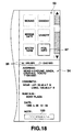
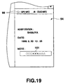
- FIGS. 18 and 19 illustrate pictures displayed in the second and third areas 53 and 54 during execution of this process.
- a position information icon 67 in the second area 53 is in a selected state and the third area 54 in a displayed state corresponding to the position information process, which comprises adding information on the present position of the electronic camera to the image object 51 displayed on the operation picture 50 (FIG. 6).
- the user may input position information while viewing a map, for example.
- a position information acquiring device such as a GPS is preferably used in terms of convenience. Information on cells of a PHS system may be available although this system can not provide a high position accuracy such as is provided by the GPS.
- Two option buttons 99 provided in the third area 54 are used to select means for acquiring position information (on one of the GPS and the cells of the PHS system in FIG. 18).
- FIG. 18 shows a picture displayed when the GPS information is used.
- FIG. 19 shows a picture obtained when the information on the cells of the PHS system is used.
- the information on the GPS basically comprises coordinates (longitude and latitude)
- the information on the cells of the PHS system basically comprises cell identification numbers, namely, information on the ID of a base station CS.
- the present position is difficult to specify only by viewing the acquired information on the GPS or the PHS cells.
- easily understandable information for example, on a written address, a nearby building or station name, etc.
- a text box 100 for a memorandum is preferably provided.
- required text input support means for example, a graphic keyboard area or handwritten character input area
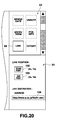
- FIG. 20 shows pictures displayed in the second and third areas 53 and 54 during execution of this process.
- a link specifying icon 68 in the second area 53 is in a selected state and the third area 54 is in a displayed state corresponding to the link specifying process, which comprises embedding link information into any portion of the image object 51 displayed on the operation picture 50 (FIG. 6), and registering information on an address of any other object, for example, its Internet URL (Uniform Resource Location) related to the link information.
- the link specifying process comprises embedding link information into any portion of the image object 51 displayed on the operation picture 50 (FIG. 6), and registering information on an address of any other object, for example, its Internet URL (Uniform Resource Location) related to the link information.
- Internet URL Uniform Resource Location
- Two button controls 102 and 103 provided in the third area 54 are each used to input coordinate information.
- a text box 104 is used to input an address of a destination to be linked with.
- the user sequentially touches with the pen tip the button control 102 written as a start point, the start point coordinates (Xs, Ys) of the image object 51, the button control 103 written as an end point, and then the end point coordinates (Xe, Ye) of the image object 51.
- the two coordinates (Xs, Ys) and (Xe, Ye) of the start and end points are read, and displayed on the respective sides of the button controls 102 and 103, and a rectangular range containing the two opposite corner coordinates (Xs, Ys) and (Xe, Ye) (and shown by a broken line in FIG. 13B) is recognized as an area where the link information is to be embedded.
- the user further touches the text box 104 with the pen tip to display required text input support means (for example, the graphic keyboard area or handwritten character input area) in a pop-up manner, and then inputs address information of a character string ( http://www.a.co.jp/file/01.way ", which implies specifying a 01.wav file present in a file directory of a http server having a www.a.co domain).
- required text input support means for example, the graphic keyboard area or handwritten character input area
- the stamp information of FIG. 8 comprising the information on the area where the link information is to be embedded and on the destination to be linked with is synthesized with the image object 51.
- the link information is a file on the server, it may be a file on a terminal. In this case, if necessary, when an image object having the link information is required to be sent to a particular receiver, it is sent along with a file of the destination to be linked with.
- a stamp may be created for each piece of link information.
- FIG. 21 shows pictures displayed in the second and third areas 53 and 54 during execution of this process.
- a category classification icon 69 in the second area 53 is in a selected state and the third area 54 is in a displayed state corresponding to the category classification process, which comprises registering on an image object 51 displayed on the operation picture 50 (FIG. 6) category classification information corresponding to the contents of an image of the image object 51.
- FOG. 6 operation picture 50
- a plurality of section icons 106-111 provided in the third area 54 each provide such selecting means and are especially elaborately wrought so that the category classifications can be understood at a glance.
- section icons 106, 107 and 108 relate to category classifications "friend", “tour” and "date”, respectively.
- a check box 105 is provided in the third area 54. By checking the box 105 off, one selected from the section icons 109-111 is pasted to the image object 51. That is, the user selects a section icon considered to be appropriate for the contents of the image object 51. In that case, the check box 105 is checked off, if necessary.
- the category classification information for the selected section icon is stored in the appropriate field for the FIG. 8 stamp information. Then, by dragging and dropping the category classification icon 69 in the second area 58 onto the image object 51, the FIG. 8 stamp information comprising the category classification information is synthesized with the image object 51.
- one of the section icons 106-111 may be dragged and dropped onto the image object 51 in place of the category classification icon 69.
- Stamp mark process (step S29 of FIG. 5):
- FIG. 22 illustrates pictures displayed in the second and third areas 53 and 54 during execution of the stamp mark process.
- a stamp mark icon 70 in the second area 53 is in a selected state and the third area 54 is in a displayed state corresponding to the stamp mark process, which comprises registering any stamp mark on the image object 51 displayed on the operation picture 50 (FIG. 6).
- a plurality of stamp marks 112-115 provided in the third area 54 comprise heart, clover, diamond and spade stamp marks arranged in this order from left to right.
- Two groups of option buttons 117 and 118 are used to select the number and size of stamp marks, respectively.
- a check box 119 is used to specify a frame display of stamp marks.
- the user selects a desired one from the stamp marks 112-115, specifies the number and size of stamp marks, using the two groups of option buttons 117 and 118, and if necessary, checks the check box 119 off to specify a frame display of the selected stamp marks.
- information on the selected stamp mark is stored in the appropriate field for the FIG. 8 stamp information.
- the stamp mark icon 70 in the second area 58 onto the image object 51 the stamp mark information is synthesized with the image object 51.
- one of the stamp marks 112-115 may be dragged and dropped onto the image object 51 in place of the stamp mark icon 70.
- the secret process step S23 of FIG. 5
- the special effect process step S25 of FIG. 5
- the image conversion 1 process step S27 of FIG. 5
- the stamp process step S29 of FIG. 5
- the attributes of the image object 51 of the first area 52 are changed or processed only by selecting, dragging and dropping any particular icon in the second area 53 onto the image object 51.
- means for inputting the information is displayed in the third area 54 to facilitate inputting the information.
- the user is able to easily perform a required process on the image object or facilitate changing the attributes of the object without requiring any special knowledge.
- Addition of attribute information to an image object in each of the above processes is performed by dragging and dropping a relevant icon onto the object 51.
- the attribute information is easily added to the respective objects, advantageously.
- FIGS. 23 and 24 are combined to provide a flowchart of a program indicative of a reproduction mode process performed by the control system 21 of the electronic still camera 1.
- This program may be performed by another information processing device, which is required to have at least a function of reproducing the respective image objects 51.
- each image object 51 is a JPEG-type image file and not subjected to processing or a change of attributes in the record mode process
- this image file can be reproduced by a personal computer, work station or portable information terminal on which a general-purpose OS such as, for example, Windows 95/98/NT/CE (registered trademark) is installed.
- a general-purpose OS such as, for example, Windows 95/98/NT/CE (registered trademark) is installed.
- the personal computer, work station and portable information terminal correspond to the information processing devices.
- Another electronic still camera capable of acquiring a JPEG-type image externally and displaying it on its monitor display also corresponds to the information processing device.
- a printer which acquires a JPEG-type image file externally and outputs the contents of the image as a hard copy also corresponds to the information processing device, of course.
- step S41 a captured image is read from the flash memory 39, expanded by the compressing/expanding system 20 (the expanded captured image is hereinafter referred to as an "image object") and displayed on the display 43.
- the captured image and display 43 should be read as an image file and a display unit of the information processing device, respectively.
- Stamp information (FIG. 8) added to the image object is then examined to determine which of the secret, special effect, image conversion 1, ..., and stamp mark processes was performed in the record mode process, and the control then branches to a reproducing process corresponding to the result of the determination.
- the determining steps include steps S42, S44, S46, S48, S50, S52, S56, S58 and S60 in FIG. 23.
- the branching steps include steps S43, S45, S47, S49, S51, S53, S57, S59 and S61 in FIG. 23.
- control branches to the secret image reproducing process in step S43.
- control branches to the special effect image reproducing process in step S45.
- step S46 when the image conversion (image conversion 1 or 2) is determined, the control branches to the image conversion reproducing process in step S47.
- step S48 when the mosaic or gradation is determined, the control branches to the mosaic or gradation image reproducing process in step S49.
- step S50 when the browse date specifying is determined, the control branches to the browse-dated image reproducing process in step S51.
- step S52 when the effective term specifying is determined, the control branches to the effective-termed image reproducing process in step S53.
- step S54 when the position information is determined, the control branches to the position informationed image reproducing process in step S55.
- step S56 when it is determined that the link was specified, the control branches to the specified-linked image reproducing process in step S57.
- step S58 when the category classification is determined, the control branches to the category-classificationed image reproducing process in step S59.
- step S60 when the stamp mark is determined, the control branches to the stamp-marked image reproducing process in step S61.
- step S62 the image object is displayed on the display 43.
- step 63 what key operation was performed.
- key operation for terminating the process the control immediately returns to step S2 of FIG. 3.
- a process similar to the stamp process (FIG. 5) performed in the record mode process that is, a process is performed which comprises changing the display picture to the operation picture described in FIG.
- step S6 displaying the captured image (image object) read in step S41 and the operation icons in the first and second areas 52 and 53, respectively, dragging and dropping a desired operation icon onto the image object (captured image) to add desired attribute control information to the image object, and the control then returns to step S2 of FIG. 3.
- FIG. 25 is a flowchart of a program indicative of this process.
- this program starts, first, in step S71 it is checked whether the information added to the image object is rightful secret information. If otherwise, the program is closed. If it is, in step S72 the control waits until a display event occurs.
- the determination as to whether the added information is rightful secret information is performed by determining whether the aded information satisfies prescribed code conditions.
- the display event includes a touch on a predetermined key or on a displayed picture by the user (this applies to the subsequent cases).
- step S73 a password requesting picture is displayed. Then, in step S74 when a password is inputted, it is determined whether the inputted password coincides with a password hidden in the image object. If otherwise, the program is closed. If it does, the control passes to step S75 to display the image object and then to close the program.
- FIG. 26 is a flowchart of a program indicative of this process.
- this program starts, first, in step S81 it is checked whether the information added to the image object is rightful special information. If otherwise, the program is closed. If it is, in step S82 the control waits until a display event occurs, at which time the control passes to step S83 to refer to control and additional information added to the image object to thereby display the image object on which an appropriate special process (flashing, spiraling or blinding, etc.) was performed, and then to close the program.
- an appropriate special process flashing, spiraling or blinding, etc.
- FIG. 27 illustrate a special effect called a slide in which a reproduced image 201 appears from down to up with time.
- the reproduced image may appear from up to down or from right to left, and vice versa.
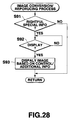
- FIG. 28 is a flowchart of a program indicative of this process.
- this program starts, first, in step S91 it is determined whether the information added to the image object is rightful image conversion information. If otherwise, the program is closed. If it is, in step S92 the control waits until a display event occurs, at which time the control passes to step S93 to refer to the control and additional information added to the image object to display the image object on which appropriate image conversion (cell rearranging puzzle in the case of the image conversion process 1; a change of the hue of the image object or a change of the color of the image object to sepia in the case of the image conversion process 2) was performed, and then to close the program.
- appropriate image conversion cell rearranging puzzle in the case of the image conversion process 1; a change of the hue of the image object or a change of the color of the image object to sepia in the case of the image conversion process 2
- FIG. 29A illustrates a puzzle in which 9 picture cells E1-E9 into which a picture 202 is divided are randomly replaced, one with another, to form a specified array of the cells 203.
- FIG. 29B illustrates that an image object 204 with a character image is changed to a different one 205 with a sepia character image.
- an image object where appropriate image conversion (the cell rearranging puzzle in the case of the image conversion process 1; a change of the hue of the image object to another and/or a change of the color of the image object to sepia in the case of the image conversion process 2) was performed is displayed.
- step S49 Mosaic or gradation image reproducing process
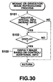
- FIG. 30 is a flowchart of a program indicative of this process.
- this program starts, first, in step S101 it is determined whether the information added to the image object is rightful control information (mosaic or gradation information). If otherwise, the program is closed. If it is, in step S102 the control waits until a display event occurs, at which time the control passes to step S103 to refer to the control and additional information added to the image object to display the image object on which a mosaic is formed or gradation is performed, and then to close the program.
- rightful control information mosaic or gradation information
- FIG. 31A illustrates that an image object 206 with a character is changed to an image object 207 where a mosaic is formed on the character.
- FIG. 31B illustrates that an image object file 209 with a character is changed to an image object file 210 with a gradated character.
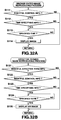
- FIG. 32A is a flowchart of a program indicative of this process.
- this program starts, first, in step S111 it is determined whether the information added to the image object is rightful control information. If otherwise, the program is closed. If it is, the control passes to step S112 to determine whether there is date/time specifying information.
- step S113 the control waits for arrival of the time and date, at which time in step S114 the image object is displayed and then the program is closed.
- step S113 if the present date is different from a specified date, the program may be closed temporarily.
- FIG. 32B is a flowchart of a program indicative of this process.
- this program starts, first, in step S121 it is determined whether the information added to the image object is rightful effective term information. If otherwise, the program is closed. If it is, the control passes to step S122 to determine whether the information is rightful control information.
- step S113 it is determined whether the control information includes date/time information. If otherwise, the program is closed. If it does, in step S124 the control waits until the date/time comes, at which time in step S125 the image object is displayed and then the program is closed.
- the program may be closed temporarily.
- the image object is not displayed excluding for the specified time.
- FIG. 33 is a flowchart of a program indicative of this process.
- this program starts, first, in step S131 it is determined whether the information added to the image object is rightful control information. If otherwise, the program is closed. If it is, the control passes to step S132 to acquire present position information.
- step S133 the control waits until a display event occurs, at which time the control passes to step S134 to refer to the control and additional information added to the image object, to display the image object with a message about the present position, and then to close the program.
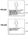
- FIG. 34A illustrates a displayed image object 211 with a position information message 212 (whose contents are also shown in FIG. 18) obtained from the GPS information.
- FIG. 34B illustrates a displayed image object 211 with a position information message 213 (whose contents are also shown in FIG. 19) obtained from information on the cells of the PHS system.
- the message about the position information added to the image object is displayed along with the image object.
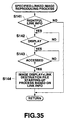
- FIG. 35 is a flowchart of a program indicative of this process.
- this program starts, first, in step S141 it is determined whether the information added to the image object is rightful link information. If otherwise, the program is closed. If it is, in step S142 the control waits until a display event occurs, at which time in step S143 the control waits until link information is accessed.
- step S144 When the link information is accessed, the control passes to step S144 to display the image object, to download an object to be linked with, to perform a process depending on a type of this object, and then to close the program.
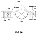
- FIG. 36 schematically illustrates this link in which it is illustrated that a "link" icon 216 on a monitor picture 215 of the electronic still camera 214 is touched to download an object (in FIG. 36, a way file stored in a server 218 connected to the Internet 217) of a link destination registered in the link section 216.
- the way file includes a file which contains voice (not limited to human voice) information.
- voice not limited to human voice
- a voice file with a name of 0.1.wav stored in a file directory of a server 218 of a www.co.jp domain can be downloaded on the still camera 214 and reproduced as it is if an executing environment of the way file is set in the still camera 214.
- an external object can be downloaded and displayed and a related sound is output based on the link information added to the image object.
- FIG. 37 is a flowchart of a program indicative of this process.
- this program starts, first, in step S151 it is determined whether the information added to the image object is rightful additional information. If otherwise, the program is closed. If it is, in step S152 information representing a category classification (for example, a classification flag) is set.
- a category classification for example, a classification flag
- step S153 the control waits until a display event occurs, at which time the control passes to step S154 to display and store an image object for each category classification, and then to close the program.
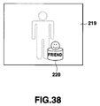
- FIG. 38 illustrates an image object on which a section icon 220 representing a category classification is pasted visually. This picture corresponds to the fact that a check box 105 of FIG. 21 indicating the category classification process is checked off.
- FIG. 39 illustrates display of an image object, using a section icon 223.
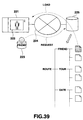
- FIG. 39 it is illustrated that for example, by clicking a section icon 223 related to a "friend" directory of a server 225 connected to the network 224, an image object (a hatched document in FIG. 39) stored in the "friend" directory is downloaded on the still camera 221 and displayed on its monitor screen 222.
- the category classification may be applicable to an object stored in a recording medium provided in the still camera 221.
- an image object is effectively managed based on the category classification information added to the image object.
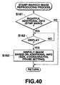
- FIG. 40 is a flowchart of a program indicative of this process.
- this program starts, first, in step S161 it is determined whether the information added to the image object is rightful additional information. If otherwise, the program is closed. If it is, in step S162 the control waits until a display event occurs, at which time the control passes to step S163 to set the size, position and number of stamp marks to be displayed or the presence/absence of a frame display, to display the image object along with the stamp marks, and then to close the program.
- FIG. 41A illustrates an image object 226 with a heart-shaped stamp mark (corresponding to an icon 112 of FIG. 22) displayed at a foot of a character.
- FIG. 41B illustrates an image object 226 surrounded by smaller stamp marks 228 arranged along the periphery of the image file.
- FIG. 41C illustrates an image object 226 with a larger stamp mark at its central position.
- an appropriate stamp mark(s) can be displayed along with the image object based on the stamp mark information added to the image object.
- a processing function may be selected depending on a position where a stamp mark is pasted on the image object.
- a password may be selected depending on whether a secret stamp mark is pasted at a right or left position on the image object (or the object display picture).
- Stamp marks "friends 1, 2, 3, " each indicative of category classification may be selected depending on their respective (upper right or lower left) pasting positions. This applies to other functions likewise.
- an effect to be produced may be changed depending on a position where a special effect stamp is pasted;
- the degree of difficulty and/or the number of divisions may be changed depending on a position where an image conversion 1 stamp is pasted;
- a brightness, contrast or gamma value may be changed depending on a position where an image conversion 2 stamp is pasted;
- a position where a mosaic is formed or a strength of the mosaic may be changed at a position where a mosaic stamp is pasted;
- G a degree of gradation may be changed at a position where a gradation stamp is pasted;
- an effective term may be changed at a position where an effective term specifying stamp is pasted;
- a type of position information to be added may be changed at a position where a position information stamp is pasted;
- a linking destination may be changed at a position where a link specifying stamp is pasted; and
- the number or size of stamp marks may be changed at a position where the
- the relationship between the function and the position where the stamp is pasted is preferably displayed in the third area 54 of the operation picture 50.
- the object is an image one (image file)
- the object may be a different object.
- the kinds of operation icons each displayed along with the object for stamp processing purposes are, of course, different from those displayed when the object is the image object.
- an operation icon displayed along with the displayed object is preferably selected automatically in correspondence to the displayed object by the control system comprising a CPU, for example.
Landscapes
- Engineering & Computer Science (AREA)
- Human Computer Interaction (AREA)
- Multimedia (AREA)
- Signal Processing (AREA)
- Theoretical Computer Science (AREA)
- General Engineering & Computer Science (AREA)
- Physics & Mathematics (AREA)
- General Physics & Mathematics (AREA)
- Computer Vision & Pattern Recognition (AREA)
- User Interface Of Digital Computer (AREA)
- Processing Or Creating Images (AREA)
- Information Retrieval, Db Structures And Fs Structures Therefor (AREA)
- Closed-Circuit Television Systems (AREA)
- Editing Of Facsimile Originals (AREA)
- Studio Devices (AREA)
- Digital Computer Display Output (AREA)
Applications Claiming Priority (2)
| Application Number | Priority Date | Filing Date | Title |
|---|---|---|---|
| JP27851199 | 1999-09-30 | ||
| JP27851199A JP2001100887A (ja) | 1999-09-30 | 1999-09-30 | オブジェクト処理装置 |
Publications (2)
| Publication Number | Publication Date |
|---|---|
| EP1089161A2 true EP1089161A2 (de) | 2001-04-04 |
| EP1089161A3 EP1089161A3 (de) | 2007-11-14 |
Family
ID=17598328
Family Applications (1)
| Application Number | Title | Priority Date | Filing Date |
|---|---|---|---|
| EP00121114A Withdrawn EP1089161A3 (de) | 1999-09-30 | 2000-09-28 | Objektverarbeitungsgerät und Verfahren zur Modifikation des Objektsattributes |
Country Status (4)
| Country | Link |
|---|---|
| EP (1) | EP1089161A3 (de) |
| JP (1) | JP2001100887A (de) |
| KR (1) | KR100372517B1 (de) |
| CN (1) | CN1208745C (de) |
Cited By (9)
| Publication number | Priority date | Publication date | Assignee | Title |
|---|---|---|---|---|
| EP1467552A3 (de) * | 2003-04-07 | 2005-07-06 | Eastman Kodak Company | Zusammengesetztes Bild mit Korrecturanzeige und Verfahren |
| WO2005031539A3 (en) * | 2003-09-26 | 2006-03-30 | Nbor Corp | Method for programming a graphic control device with numeric and textual characters |
| EP1885113A1 (de) * | 2006-08-04 | 2008-02-06 | Nikon Corporation | Digitalkamera mit dynamischem Menü zur optionale Bildverarbeitung |
| EP1596570A3 (de) * | 2004-05-12 | 2008-06-04 | Samsung Electronics Co., Ltd. | Ein Dokumentenscanner mit einer Editierfunktion |
| EP1950943A3 (de) * | 2004-03-29 | 2008-08-13 | FUJIFILM Corporation | Digitale Standbildkamera und Verfahren zu ihrer Ansteuerung |
| US8379031B2 (en) | 2006-08-31 | 2013-02-19 | Canon Kabushiki Kaisha | Image data management apparatus, image data management method, computer-readable storage medium |
| US8988749B2 (en) | 2011-06-22 | 2015-03-24 | Lg Electronics Inc. | Scanning technology |
| EP2433685A3 (de) * | 2010-09-28 | 2016-09-21 | Nintendo Co., Ltd. | Informationsverarbeitungsvorrichtung zur Zuweisung von Daten miteinander, Informationsverarbeitungssystem und Informationsverarbeitungsprogramm |
| US11245802B2 (en) * | 2019-01-11 | 2022-02-08 | Fujifilm Business Innovation Corp. | Information processing apparatus and non-transitory computer readable medium |
Families Citing this family (10)
| Publication number | Priority date | Publication date | Assignee | Title |
|---|---|---|---|---|
| US7421438B2 (en) * | 2004-04-29 | 2008-09-02 | Microsoft Corporation | Metadata editing control |
| US7474310B2 (en) * | 2005-08-12 | 2009-01-06 | Microsoft Corporation | Object association in a computer generated drawing environment |
| JP4991462B2 (ja) * | 2007-09-14 | 2012-08-01 | キヤノン株式会社 | 画像処理装置およびその制御方法およびプログラム |
| KR101467293B1 (ko) * | 2008-04-22 | 2014-12-02 | 삼성전자주식회사 | 촬영될 영상에 관련된 메뉴를 표시하는 ui 제공방법 및이를 적용한 촬영장치 |
| KR101347518B1 (ko) * | 2010-08-12 | 2014-01-07 | 주식회사 팬택 | 필터의 선택이 가능한 증강 현실 사용자 장치 및 방법, 그리고, 증강 현실 서버 |
| KR101735302B1 (ko) | 2010-10-13 | 2017-05-15 | 삼성전자 주식회사 | 카메라의 빠른 연계 기능 실행 방법 및 이를 포함하는 휴대 단말기 |
| CN104202514A (zh) * | 2014-07-30 | 2014-12-10 | 惠州Tcl移动通信有限公司 | 一种产生标准照片的方法及终端 |
| CN106911887A (zh) * | 2015-12-28 | 2017-06-30 | 小米科技有限责任公司 | 图像拍摄方法及装置 |
| JP6410884B2 (ja) * | 2017-06-27 | 2018-10-24 | オリンパス株式会社 | 操作設定装置、操作設定方法、およびプログラム |
| CN113900737A (zh) * | 2021-10-19 | 2022-01-07 | 维沃移动通信有限公司 | 应用程序管理方法、装置和电子设备 |
Family Cites Families (3)
| Publication number | Priority date | Publication date | Assignee | Title |
|---|---|---|---|---|
| US5371844A (en) * | 1992-03-20 | 1994-12-06 | International Business Machines Corporation | Palette manager in a graphical user interface computer system |
| US5900874A (en) * | 1992-05-11 | 1999-05-04 | International Business Machines Corporation | Icon transformation system |
| WO1997044726A1 (en) * | 1996-05-06 | 1997-11-27 | Adobe Systems Incorporated | Internet hyperlink drag and drop |
-
1999
- 1999-09-30 JP JP27851199A patent/JP2001100887A/ja active Pending
-
2000
- 2000-09-28 EP EP00121114A patent/EP1089161A3/de not_active Withdrawn
- 2000-09-29 KR KR10-2000-0057348A patent/KR100372517B1/ko not_active Expired - Fee Related
- 2000-09-30 CN CNB001323598A patent/CN1208745C/zh not_active Expired - Fee Related
Cited By (13)
| Publication number | Priority date | Publication date | Assignee | Title |
|---|---|---|---|---|
| EP1467552A3 (de) * | 2003-04-07 | 2005-07-06 | Eastman Kodak Company | Zusammengesetztes Bild mit Korrecturanzeige und Verfahren |
| WO2005031539A3 (en) * | 2003-09-26 | 2006-03-30 | Nbor Corp | Method for programming a graphic control device with numeric and textual characters |
| EP1950943A3 (de) * | 2004-03-29 | 2008-08-13 | FUJIFILM Corporation | Digitale Standbildkamera und Verfahren zu ihrer Ansteuerung |
| EP1596570A3 (de) * | 2004-05-12 | 2008-06-04 | Samsung Electronics Co., Ltd. | Ein Dokumentenscanner mit einer Editierfunktion |
| US7558511B2 (en) | 2004-05-12 | 2009-07-07 | Samsung Electronics Co., Ltd | Scanning apparatus and method having editing function, and multi functional peripheral using the scanning method |
| US8885056B2 (en) | 2006-08-04 | 2014-11-11 | Nikon Corporation | Digital camera |
| EP1885113A1 (de) * | 2006-08-04 | 2008-02-06 | Nikon Corporation | Digitalkamera mit dynamischem Menü zur optionale Bildverarbeitung |
| US8754952B2 (en) | 2006-08-04 | 2014-06-17 | Nikon Corporation | Digital camera |
| US8379031B2 (en) | 2006-08-31 | 2013-02-19 | Canon Kabushiki Kaisha | Image data management apparatus, image data management method, computer-readable storage medium |
| EP2433685A3 (de) * | 2010-09-28 | 2016-09-21 | Nintendo Co., Ltd. | Informationsverarbeitungsvorrichtung zur Zuweisung von Daten miteinander, Informationsverarbeitungssystem und Informationsverarbeitungsprogramm |
| US8988749B2 (en) | 2011-06-22 | 2015-03-24 | Lg Electronics Inc. | Scanning technology |
| EP2538650B1 (de) * | 2011-06-22 | 2019-03-13 | LG Electronics Inc. | Grafische Benutzeroberfläche |
| US11245802B2 (en) * | 2019-01-11 | 2022-02-08 | Fujifilm Business Innovation Corp. | Information processing apparatus and non-transitory computer readable medium |
Also Published As
| Publication number | Publication date |
|---|---|
| KR100372517B1 (ko) | 2003-02-19 |
| JP2001100887A (ja) | 2001-04-13 |
| CN1291758A (zh) | 2001-04-18 |
| KR20010050753A (ko) | 2001-06-15 |
| CN1208745C (zh) | 2005-06-29 |
| EP1089161A3 (de) | 2007-11-14 |
Similar Documents
| Publication | Publication Date | Title |
|---|---|---|
| EP1089161A2 (de) | Objektverarbeitungsgerät und Verfahren zur Modifikation des Objektsattributes | |
| US6629104B1 (en) | Method for adding personalized metadata to a collection of digital images | |
| KR100674402B1 (ko) | 화상 처리 장치, 화상 처리 방법 및 저장 매체 | |
| US6816189B2 (en) | Electron camera and method of controlling the same | |
| US7970240B1 (en) | Method and apparatus for archiving and visualizing digital images | |
| US7444354B2 (en) | Method and apparatus for storing images, method and apparatus for instructing image filing, image storing system, method and apparatus for image evaluation, and programs therefor | |
| US6795094B1 (en) | Method and apparatus for processing an image, and storage | |
| US20060239676A1 (en) | Method for rating images to facilitate image retrieval | |
| KR101475939B1 (ko) | 이미지 처리 장치의 제어 방법과 이미지 처리 장치, 이미지파일 | |
| KR20060092075A (ko) | 정보 처리 장치, 정보 처리 방법, 정보 처리 시스템 | |
| JP2001222433A (ja) | 情報記録媒体、情報処理方法、情報処理装置、及びプログラム記録媒体 | |
| US20110131529A1 (en) | Information Processing Apparatus, Information Processing Method, Computer Program, and Information Processing Server | |
| US20060098105A1 (en) | Digital camera and computer program | |
| CN107016034A (zh) | 信息处理装置及信息处理方法 | |
| US7578441B2 (en) | Data retrieval method and apparatus | |
| US6038365A (en) | Image retrieval-oriented processing apparatus which generates and displays search image data that is used as index | |
| JP2000010471A (ja) | 地図表示装置及び方法 | |
| JP2001036840A (ja) | 電子地図を用いた撮影画像管理方法及び撮影画像再生方法及びそれらの装置 | |
| KR20040104574A (ko) | 화상 표시용 프로그램 및 그 프로그램이 기록된 정보 기록매체 | |
| JP2005196529A (ja) | 画像分類プログラム | |
| JP4089097B2 (ja) | データ保存装置及びデータ記憶方法 | |
| CN100397861C (zh) | 数据文件存储设备和数据文件存储方法 | |
| HK1038079A (en) | Object processing apparatus and object attribute changing methods | |
| JP2003067722A (ja) | 画像情報管理方法及びシステム | |
| JP2002369107A (ja) | 画像情報記録装置、画像情報記録システム及び画像情報記録装置制御プログラム |
Legal Events
| Date | Code | Title | Description |
|---|---|---|---|
| PUAI | Public reference made under article 153(3) epc to a published international application that has entered the european phase |
Free format text: ORIGINAL CODE: 0009012 |
|
| 17P | Request for examination filed |
Effective date: 20000928 |
|
| AK | Designated contracting states |
Kind code of ref document: A2 Designated state(s): AT BE CH CY DE DK ES FI FR GB GR IE IT LI LU MC NL PT SE |
|
| AX | Request for extension of the european patent |
Free format text: AL;LT;LV;MK;RO;SI |
|
| PUAL | Search report despatched |
Free format text: ORIGINAL CODE: 0009013 |
|
| AK | Designated contracting states |
Kind code of ref document: A3 Designated state(s): AT BE CH CY DE DK ES FI FR GB GR IE IT LI LU MC NL PT SE |
|
| AX | Request for extension of the european patent |
Extension state: AL LT LV MK RO SI |
|
| AKX | Designation fees paid |
Designated state(s): DE FR GB |
|
| STAA | Information on the status of an ep patent application or granted ep patent |
Free format text: STATUS: THE APPLICATION IS DEEMED TO BE WITHDRAWN |
|
| 18D | Application deemed to be withdrawn |
Effective date: 20080515 |
|
| REG | Reference to a national code |
Ref country code: HK Ref legal event code: WD Ref document number: 1038079 Country of ref document: HK |