EP1089251A1 - Trommel mit Wand, bestehend aus mehreren Vibrationselementen, welche parallel zum Fell angeordnet sind - Google Patents
Trommel mit Wand, bestehend aus mehreren Vibrationselementen, welche parallel zum Fell angeordnet sind Download PDFInfo
- Publication number
- EP1089251A1 EP1089251A1 EP00121427A EP00121427A EP1089251A1 EP 1089251 A1 EP1089251 A1 EP 1089251A1 EP 00121427 A EP00121427 A EP 00121427A EP 00121427 A EP00121427 A EP 00121427A EP 1089251 A1 EP1089251 A1 EP 1089251A1
- Authority
- EP
- European Patent Office
- Prior art keywords
- drum
- skin
- cylindrical member
- component
- end surface
- Prior art date
- Legal status (The legal status is an assumption and is not a legal conclusion. Google has not performed a legal analysis and makes no representation as to the accuracy of the status listed.)
- Granted
Links
- 239000002131 composite material Substances 0.000 claims abstract description 74
- 239000000463 material Substances 0.000 claims description 23
- 230000000644 propagated effect Effects 0.000 claims description 23
- 229910052751 metal Inorganic materials 0.000 claims description 10
- 239000002184 metal Substances 0.000 claims description 10
- 239000002023 wood Substances 0.000 claims description 9
- 230000001902 propagating effect Effects 0.000 claims description 7
- 229920003002 synthetic resin Polymers 0.000 description 7
- 239000000057 synthetic resin Substances 0.000 description 7
- 235000018185 Betula X alpestris Nutrition 0.000 description 3
- 235000018212 Betula X uliginosa Nutrition 0.000 description 3
- 240000000731 Fagus sylvatica Species 0.000 description 3
- 235000010099 Fagus sylvatica Nutrition 0.000 description 3
- 241000208140 Acer Species 0.000 description 2
- 229910001369 Brass Inorganic materials 0.000 description 2
- 229920002430 Fibre-reinforced plastic Polymers 0.000 description 2
- XEEYBQQBJWHFJM-UHFFFAOYSA-N Iron Chemical compound [Fe] XEEYBQQBJWHFJM-UHFFFAOYSA-N 0.000 description 2
- 238000010521 absorption reaction Methods 0.000 description 2
- 229910045601 alloy Inorganic materials 0.000 description 2
- 239000000956 alloy Substances 0.000 description 2
- 229910052782 aluminium Inorganic materials 0.000 description 2
- XAGFODPZIPBFFR-UHFFFAOYSA-N aluminium Chemical compound [Al] XAGFODPZIPBFFR-UHFFFAOYSA-N 0.000 description 2
- 239000010951 brass Substances 0.000 description 2
- 230000000052 comparative effect Effects 0.000 description 2
- 239000000356 contaminant Substances 0.000 description 2
- 239000011151 fibre-reinforced plastic Substances 0.000 description 2
- -1 for example Inorganic materials 0.000 description 2
- 230000008646 thermal stress Effects 0.000 description 2
- WURBVZBTWMNKQT-UHFFFAOYSA-N 1-(4-chlorophenoxy)-3,3-dimethyl-1-(1,2,4-triazol-1-yl)butan-2-one Chemical compound C1=NC=NN1C(C(=O)C(C)(C)C)OC1=CC=C(Cl)C=C1 WURBVZBTWMNKQT-UHFFFAOYSA-N 0.000 description 1
- 244000046151 Acer negundo Species 0.000 description 1
- 235000004422 Acer negundo Nutrition 0.000 description 1
- 208000019901 Anxiety disease Diseases 0.000 description 1
- 235000017166 Bambusa arundinacea Nutrition 0.000 description 1
- 235000017491 Bambusa tulda Nutrition 0.000 description 1
- RYGMFSIKBFXOCR-UHFFFAOYSA-N Copper Chemical compound [Cu] RYGMFSIKBFXOCR-UHFFFAOYSA-N 0.000 description 1
- 241001494479 Pecora Species 0.000 description 1
- 244000082204 Phyllostachys viridis Species 0.000 description 1
- 235000015334 Phyllostachys viridis Nutrition 0.000 description 1
- 241000208967 Polygala cruciata Species 0.000 description 1
- 239000000853 adhesive Substances 0.000 description 1
- 230000001070 adhesive effect Effects 0.000 description 1
- 230000036506 anxiety Effects 0.000 description 1
- 239000011425 bamboo Substances 0.000 description 1
- 150000001875 compounds Chemical class 0.000 description 1
- 230000008602 contraction Effects 0.000 description 1
- 229910052802 copper Inorganic materials 0.000 description 1
- 239000010949 copper Substances 0.000 description 1
- 229910052742 iron Inorganic materials 0.000 description 1
- 239000010985 leather Substances 0.000 description 1
- 238000012986 modification Methods 0.000 description 1
- 230000004048 modification Effects 0.000 description 1
- 230000010355 oscillation Effects 0.000 description 1
- 238000009527 percussion Methods 0.000 description 1
- 229920005668 polycarbonate resin Polymers 0.000 description 1
- 239000004431 polycarbonate resin Substances 0.000 description 1
- 229920001225 polyester resin Polymers 0.000 description 1
- 239000004645 polyester resin Substances 0.000 description 1
- 230000033764 rhythmic process Effects 0.000 description 1
Images



Classifications
-
- G—PHYSICS
- G10—MUSICAL INSTRUMENTS; ACOUSTICS
- G10D—STRINGED MUSICAL INSTRUMENTS; WIND MUSICAL INSTRUMENTS; ACCORDIONS OR CONCERTINAS; PERCUSSION MUSICAL INSTRUMENTS; AEOLIAN HARPS; SINGING-FLAME MUSICAL INSTRUMENTS; MUSICAL INSTRUMENTS NOT OTHERWISE PROVIDED FOR
- G10D13/00—Percussion musical instruments; Details or accessories therefor
- G10D13/10—Details of, or accessories for, percussion musical instruments
- G10D13/22—Shells
Definitions
- This invention relates to a percussion instrument and, more particularly, to a drum having a composite shell.
- drum such as, for example, a bass drum, a snare drum, a military drum and a floor tom are used in the rhythm section for giving the beat.
- the drum is usually broken down into a shell, a skin or skins and a fastening means.
- the shell is a tubular member, and the skin is stretched over an opening of the shell.
- the fastening means is provided between the shell and the skin for integrating the skin with the shell.
- a performer strikes the skin by sticks or a drum- beater so as to give the beat.
- a column of air is defined inside the shell, and serves as a vibration propagating medium.
- the shell is expected to exhibit good vibration characteristics as well as the geometric stability.
- the skin is stretched over the opening, and is fastened to the shell.
- a snare drum has a snappy stretched over the bottom opening together with the skin, and is also fastened to the shell.
- the skins and the snappy exert tension on the shell.
- Material is expanded and contracted depending upon the ambient temperature, and the expansion and the contraction is causative of the thermal stress.
- the shell is to maintain the geometry or the shape against the tension and the thermal stress.
- the dimensions of the shell are influential on the column of air, and well-tuned beat sound is generated through the stable column of air.
- the geometric stability is influential on the sound quality, and, accordingly, is one of the substantial properties of the shell.
- the shell is to be prohibited from the self- oscillation and the self-absorption, and is designed to have vibration characteristics without self-oscillation and self-absorption.
- the vibration characteristics of the shell are also influential on the tone quality.
- the material of the shell is a non-ignoreable factor of the vibration characteristics.
- the shell is usually formed of wood, metal/alloy such as, for example, aluminum or fiber-reinforced synthetic resin usually referred to as FRP (Fiber-Reinforced Plastic).
- the shell formed of metal or fiber-reinforced synthetic resin propagates the vibrations at relatively high speed, and high-frequency vibrations are much liable to be propagated through the metal/ fiber-reinforced synthetic resin shell.
- the beat sound propagated through the metal/ fiber-reinforced synthetic resin shell tends to be rapidly decayed. This results in sharp bright beat sound.
- the woody shell propagates the vibrations at relatively low speed, and low-frequency vibrations are much liable to be propagated through the woody shell.
- the decay time is longer than that of the metallic shell. This results in gentle beat sound.
- the woody shells are the majority of the material for the shells commercially sold on the market. Drummers have deep interest and anxiety on new beat sound, and request the manufacturer to design a new drum for producing beat sound different in sound quality from the conventional beat sound.
- U.S. Patent No. 5,377,576 discloses a composite shell, which consists of three tubular elements. A woody tubular element is sandwiched between two metallic tubular elements, and the three tubular elements are connected in series. The three tubular elements are assembled into the composite shell.
- the woody tubular element has thin portions at both ends thereof, and the thin portions and the remaining portion form steps at the boundary therebetween.
- Each of the metallic tubular elements has a thin portion at one end thereof, and the thin portion and the remaining portion form a step at the boundary therebetween.
- the thin portions of the woody tubular element and the thin portions of the metallic tubular elements form socket-and- spigot joints.
- the thin portions of the metallic tubular elements are inserted into the thin portions of the woody tubular element, and are assembled with the woody tubular element by means of the socket-and- spigot joints.
- the metallic tubular members are formed with projections, respectively, and through- holes are respectively formed in the projections.
- the woody tubular member is also formed with a projection, and threaded holes are formed.
- Bolts pass through the through- holes, respectively, and are screwed into the threaded holes.
- the bolts press the metallic tubular elements to the woody tubular element, and the metallic tubular elements are fixed to the woody tubular element.
- the metallic tubular elements are connected in series to the woody tubular element, and the metallic tubular elements and the woody tubular element form in combination the composite shell. Skins are stretched over the openings of the composite shell, and are fastened thereto.
- the present inventor contemplated the problems inherent in the prior art drum, and noticed that the vibrations were propagated from the skin through the metallic tubular element to the woody tubular element. In other words, the vibrations were to be propagated through the boundary between the metal tubular element and the woody tubular element. This meant that the boundary conditions had strong influence on the magnitude of the vibrations propagated to the woody tubular element, and the vibrations lost non-ignoreable amount of vibrational energy at the boundary. In this situation, the vibrations of the metallic tubular element dominated the sound quality of the beat sound. The present inventor concluded that the vibrations were to be evenly propagated from the skin to the shell components.
- the present invention proposes to connect more than one shell components to an origin of vibrations in parallel.
- a drum comprising a composite shell including a first component member formed of a first material and a second component formed of a second material different in vibration propagating property from the first material and assembled with the first component so as to be exposed to an end surface of the first component defining an aperture, at least one skin stretched over the aperture and held in contact with the end surface for propagating vibrations to the first component and the second component and a fastening means for fixing the at least one skin to the composite shell.
- reference numeral 1 designates a snare drum embodying the present invention.
- the snare drum 1 largely comprises a composite shell 2, a pair of skins 3 and a fastening means 4.
- the composite shell 2 has a tubular shape, and a vent hole 5 is formed in the composite shell 2.
- the inner space of the composite shell is connected through the vent hole 5 to the outside thereof.
- Circular apertures 2a/ 2b are defined at both ends of the composite shell 2, and skins 3A/ 3B are stretched over the circular apertures 2a/ 2b, respectively.
- the skins 3A/ 3B are fixed to the composite shell 2 by means of the fastening means 4.
- the composite shell 2 is fabricated from two kinds of components 2c/ 8, i.e., a woody cylindrical member 2c and a plurality of metallic bars 8.
- the woody cylindrical member 2c is sharpened at both ends thereof. For this reason, there are inclined end surfaces between the inner surface and the outer surface of the woody cylindrical member 2c. Holes are formed in the woody cylindrical member 2c, and the holes are selectively open to the inclined end surfaces of the woody cylindrical member 2c.
- the metallic bars 8 are inserted into the holes, and are snugly received. Thus, the metallic bars 8 are embedded in the woody cylindrical member 2c, and are exposed to the inclined end surfaces.
- the metallic bars 8 are exposed to the inclined end surface defining the circular aperture 2a, and the other half of the metallic bars 8 are exposed to the inclined end surface defining the other circular aperture 2b.
- the metallic bars 8 exposed to one of the inclined end surfaces are respectively paired with the remaining metallic bars 8, and the pairs of metallic bars 8 are on virtual lines substantially parallel to the center line of the composite shell 2 as shown in figure 3.
- the skins 3A/ 3B or drum heads are held in contact with the inclined end surfaces, respectively, and are fixed to the composite shell 2 by means of the fastening means 4.
- a column of air 9 is defined by the woody cylindrical member 2c and the skins 3A/ 3B.
- the woody cylindrical member 2c is a monolithic structure, and any socket-and- spigot join is not required for the composite shell 2.
- the monolithic cylindrical member 2c is larger in mechanical strength than the woody tubular element connected to the metallic tubular elements by means of the socket-and- spigot joints.
- the metallic bars 8 reinforce the woody cylindrical member 2c. Even if large external force is exerted on the composite shell 2, the composite shell 2 withstands the large external force, and is hardly broken.
- the woody cylindrical member 2c is formed as follows. Maple, birch and beech have fairly large hardness and good acoustic properties, and are appropriate for the woody cylindrical member 2c.
- a rotary lathe is prepared. A log of maple tree/ birch tree/ beech tree is placed on the rotary lathe. The rotary lathe peels the log. Then, sheets of maple wood/ birch wood/ beech wood are obtained from the log. The woody sheets are thin and constant in thickness.
- the woody sheets are laminated, and are bonded to one another.
- the laminated wood plate is rounded into a cylindrical shape. A side portion of the laminated wood plate is secured to the other side portion, and both end portions are obliquely cut off so as to form the inclined end surfaces.
- the inclined end surfaces make the contact between the skins 3A/ 3B and the composite shell 2 clear.
- the holes are formed in both end portions of the woody cylindrical member 2c. The holes are equally spaced along the periphery of the composite shell 2 at regular intervals. Five to twenty holes are formed in each end portion of the woody cylindrical member 2c.
- the metallic bars 8 are, by way of example, formed of iron, brass, copper or aluminum.
- the metal bars 8 are 1- 6 millimeters in diameter.
- the length of the metallic bars 8 is variable together with the volume of the composite shell 2.
- Standard metallic bars 8 are of the order of 10 millimeters long.
- the metallic bars 8 are adhered to the woody cylindrical member 2c by means of adhesive compound.
- the metallic bars 8 are formed of brass, and are 5 millimeters in diameter and 45 millimeters in length. Twenty metallic bars are embedded in each end portion of the woody cylindrical member 2c, and, accordingly, forty metallic bars 8 are arranged in both end portions of the woody cylindrical member 2c.
- the skins 3A/ 3B are formed of natural leather or synthetic resin such as, for example, polyester resin or polycarbonate resin. Constant tension is exerted on the skin 3A/ 3B, and the skin 3A/ 3B is stretched over the circular opening 2a/ 2b.
- the skins 3A/ 3B are secured to the composite shell 2, and are held in contact with the inclined end surfaces. Thus, the circular apertures 2a/ 2b are closed with the skins 3A/ 3B.
- the air of column 9 is confined inside of the composite shell 2, and vibrations are propagated from the vibrating skin 3A through the column of air 9 to the other skin 3B.
- the fastening means 4 includes hoops 10, rims 11, lugs 12 and bolts 13. As will be best seen in figure 3, the skins 3A/ 3B are respectively anchored at the hoops 10, and the end portions of the composite shell 2 are inserted into the hoops 10.
- the rims 11 are attached to the hoops 10, respectively, and through-holes are formed in the rims 11 at regular intervals.
- the lugs 12 are fixed to the woody cylindrical member 2c at the regular intervals, and threaded holes are formed on both end portions of each lug 12.
- the bolts pass through the through- holes, and are screwed into the threaded holes formed in the lugs 12.
- the rims 11 are forced to advance toward the lugs 12, and press the hoops 10.
- the hoops 10 stretch the skins 3A/ 3B, and tension is exerted to the skins 3A/ 3B.
- the tension is regulable by turning the bolts 13.
- the fastening means 4 fixes the skins 3A/ 3B to the composite shell 2, and exerts tension on the skins 3A/ 3B.
- the woody cylindrical member 2c is the monolithic structure, and forms the inclined end surfaces where the skins 3A/ 3B are held in contact.
- the vibrations are directly propagated from the skin 3A/ 3B to the woody cylindrical member 2c and vice versa without serious energy loss.
- the metallic bars 8 are exposed to the inclined end surfaces, and the vibrations are also propagated from the skins 3A/ 3B to the metallic bars 8.
- the skins 3A/ 3B give rise to the vibrations in both of the woody cylindrical member 2c and the metallic bars 8. This results in new sound quality between the sound quality produced through the woody shell and the sound quality produced through the metallic shell.
- the present inventor investigated the quality of the beat sound.
- the present inventor prepared the drum shown in figure 3 and a comparative drum with a woody shell.
- the present inventor measured the vibrations of the woody cylindrical member 2c as well as the vibrations of the metallic bars 8.
- the present inventor further measured the vibrations of the woody shell of the comparative drum.
- the present inventor firstly confirmed that the vibrations were concurrently transferred from the skin 3A/ 3B to the woody cylindrical member 2c and the metallic bars 8.
- the propagation speed in the metallic bars 8 was larger than that in the woody cylindrical bars 8, and the vibrations were propagated through the composite shell 2 between the skins 3A and 3B at a relatively high propagation speed.
- the propagation speed in the woody shell was small, and the vibrations were propagated between the skins through the woody shell at a relatively small propagation speed.
- the difference in propagation sheep resulted in sound quality.
- the present inventor confirmed that the beat sound produced through the drum 1 was different from the beat sound produced through the prior art drum with a woody shell as well as the beat sound produced through the prior art drum with a metallic shell.
- the drum 1 according to the present invention produced the new beat sound.
- the present inventor further investigated influences of the metallic bars 8 on the sound quality.
- the present inventor prepared the composite shells 2, which were different in the number of metallic bars and the dimensions of metallic bars from one another.
- the present inventors selected composite shells, the metallic bars of which were equal in number but different in dimensions.
- the present inventor compared the sound quality produced through those composite shells with one another.
- the present inventor confirmed that the metallic bars accelerated the propagation of vibrations between the skins. The longer the metallic bars, the larger the propagation speed. Accordingly, when the beat sound was produced through the composite shell with long metallic bars, the sound quality was closer to that of the metallic shell than the sound quality produced through the composite shell with short metallic bars.
- the present inventor selected another set of composite shells, the metallic bars of which were equal in dimensions but different in number.
- the beat sound was produced through the composite shell with a large number of metallic bars, the sound quality was closer to that of the metallic shell than the sound quality produced through a composite shell with a small number of metallic bars.
- the present invention further investigated influences of the socket-and-spigot joint.
- the present inventor measured the vibrational energy.
- the present inventor confirmed that the energy loss was much smaller in the composite shell 2 than the energy loss in the prior art composite shell with the socket-and- spigot joints. Accordingly, the drum according to the present invention generated the beat sound much larger in loudness than the beat sound of the prior art drum.
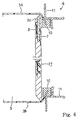
- FIG 4 of the drawings another drum embodying the present invention largely comprises a composite shell, skins 3A/ 3B and a fastening means 4.
- the skins 3A/ 3B and the fastening means 4 are similar to those of the first embodiment, and no further description is incorporated hereinbelow.
- the composite shell is broken down into a woody cylindrical member 2f and metallic bars 8.
- the woody cylindrical member 2f also has inclined end surfaces 2a/ 2b. Although the holes are open to both inclined end surfaces 2a/ 2b in the woody cylindrical member 2c, all the holes are open to the inclined end surface 2a of the woody cylindrical member 2f.
- the metallic bars 8 modify the quality of beat sound produced through the composite shell of the second embodiment, and the sound quality is a contaminant between the sound quality produced through the woody shell and the sound quality produced through the metallic shell.
- the present inventor investigated the influences of the metallic bars, and confirmed that the sound quality was modifiable depending upon the dimensions and the number of the metallic bars as similar to the first embodiment.
- yet another drum embodying the present invention also largely comprises a composite shell, skins 3A/ 3B and a fastening means 4.
- the skins 3A/ 3B and the fastening means 4 are similar to those of the first embodiment, and no further description is incorporated hereinbelow.
- the composite shell is broken down into a woody cylindrical member 2h and metallic bars 8.
- the woody cylindrical member 2h also has inclined end surfaces 2a/ 2b. Although the holes of each pair are separated from each other in the woody cylindrical member 2c, the holes open to the inclined end surface 2a are respectively connected to the associated holes in the woody cylindrical member 2h. In other words, all the through holes are open to both inclined end surfaces 2a/ 2b in the woody cylindrical member 2h. Accordingly, the metallic bars 8 are as long as the woody cylindrical member 2h, and are open to both inclined end surfaces 2a/ 2b.
- the metallic bars 8 modify the quality of beat sound produced through the composite shell of the third embodiment, and the sound quality is a contaminant between the sound quality produced through the woody shell and the sound quality produced through the metallic shell.
- the present inventor investigated the influences of the metallic bars, and confirmed that the sound quality was modifiable depending upon the dimensions and the number of the metallic bars as similar to the first embodiment.
- FIG 6 of the drawings still another drum embodying the present invention also largely comprises a composite shell, skins 3A and a fastening means.
- the skins 3 and the fastening means are similar to those of the first embodiment, and no further description is incorporated hereinbelow.
- the composite shell is broken down into a woody cylindrical member 2j and metallic bars 8a.
- the woody cylindrical member 2j has ridge end surfaces 2k, and the center axes of the holes are on the ridge lines of the end surfaces 2k.
- the metallic bar 8a has a ridge end, and the ridge end is same in shape as the ridge end surface of the woody cylindrical member 2j.
- the ridge ends are coplanar with the ridge end surfaces, and the metallic bars 8a form parts of the ridge lines of the composite shell.
- the skins 3 are stretched and fastened to the composite shell, the skins 3 are pressed against the ridge lines, respectively, and vibrations are directly propagated to the metallic bars 8a as well as the woody cylindrical member 2j.
- the present inventor also investigated the influences of the metallic bars 8a on the sound quality, and confirmed that the sound quality was modifiable with the dimensions and the number of the metallic bars 8a.
- the vibrations are propagated from the skin to the metallic bars and the woody cylindrical member substantially in parallel.
- the vibrating skin concurrently gives rise to vibrations in the metallic bars as well as in the woody cylindrical member, and the sound quality is never dominated by neither metallic bars nor the woody cylindrical member. This results in new beat sound between the beat sound produced through the woody shell and the beat sound produced through the metallic shell.
- the woody cylindrical member has a monolithic structure, and does not contain any joint. For this reason, the vibrations are propagated through the woody cylindrical member without serious energy loss, and a drummer generates loud beat sound with the drum according to the present invention.
- the metallic bars are embedded in the woody cylindrical member, and, accordingly, reinforce the woody cylindrical member. This results in that the composite shell is not damaged under the usual conditions.
- the present invention is applicable to any kind of drum such as, for example, a bass drum, tom-toms, a side drum, tenor drum and a military drum.
- a snappy may be stretched over a skin. Only one skin may be stretched over one of the apertures of the composite drum.
- the metallic bars may be replaced with metallic plates.
- the metallic plates may be inserted into slits formed in a woody cylindrical member, and are exposed to the end surfaces of the woody cylindrical member.
- the metallic bars may be formed of another kind of alloy or metal.
- the metallic bars may be replaced with bars formed of fiber- reinforced synthetic resin.
- a composite shell according to the present invention may further include a third component different in vibration characteristics from the cylindrical member and the metallic bars.
- wood, metal and fiber- reinforced synthetic resin are popular, other material is available for the composite shell.
- other material is, by way of example, bamboo.
- a drum comprising a composite shell (2) formed from a first component member (2c;2f;2h;2j) and a second component (8) and having an end surface for defining an aperture (2a). at least one skin (3/3A) and a fastening means (4) for fixing at least one skin (3/3A) to said composite shell (2), characterized in that said first component (2c;2f;2h;2j) and said second component are exposed to said end surface.
Landscapes
- Physics & Mathematics (AREA)
- Engineering & Computer Science (AREA)
- Acoustics & Sound (AREA)
- Multimedia (AREA)
- Toys (AREA)
- Golf Clubs (AREA)
- Building Environments (AREA)
- Stringed Musical Instruments (AREA)
Applications Claiming Priority (2)
| Application Number | Priority Date | Filing Date | Title |
|---|---|---|---|
| JP27965799 | 1999-09-30 | ||
| JP27965799A JP3451996B2 (ja) | 1999-09-30 | 1999-09-30 | ドラム |
Publications (2)
| Publication Number | Publication Date |
|---|---|
| EP1089251A1 true EP1089251A1 (de) | 2001-04-04 |
| EP1089251B1 EP1089251B1 (de) | 2006-05-03 |
Family
ID=17614049
Family Applications (1)
| Application Number | Title | Priority Date | Filing Date |
|---|---|---|---|
| EP00121427A Expired - Lifetime EP1089251B1 (de) | 1999-09-30 | 2000-09-29 | Trommel mit Wand, bestehend aus mehreren Vibrationselementen, welche parallel zueinander zum Fell angeordnet sind |
Country Status (4)
| Country | Link |
|---|---|
| US (1) | US6380468B1 (de) |
| EP (1) | EP1089251B1 (de) |
| JP (1) | JP3451996B2 (de) |
| DE (1) | DE60027660T2 (de) |
Cited By (3)
| Publication number | Priority date | Publication date | Assignee | Title |
|---|---|---|---|---|
| WO2006111753A3 (en) * | 2005-04-22 | 2007-03-08 | John Whalley | Drum shell |
| EP2763133A1 (de) * | 2009-06-08 | 2014-08-06 | Roland Corporation | Schlaginstrumentensysteme und -verfahren |
| US10313005B2 (en) | 2014-10-07 | 2019-06-04 | Sedonasys Systems Ltd | Systems and methods for managing multilayer communication networks |
Families Citing this family (11)
| Publication number | Priority date | Publication date | Assignee | Title |
|---|---|---|---|---|
| US6927330B2 (en) * | 2003-06-24 | 2005-08-09 | Randall L. May | Drum with modulated acoustic air vent |
| US7291776B2 (en) * | 2003-12-08 | 2007-11-06 | Dunnett Ronn J | Adjustable venturi for a drum |
| US7326842B2 (en) * | 2004-12-23 | 2008-02-05 | Randall L May | Mono postal percussion instrument carrier |
| US7485791B2 (en) * | 2007-01-12 | 2009-02-03 | Pearl Musical Instrument Co. | Golden ratio air vent holes |
| WO2009151564A1 (en) * | 2008-06-11 | 2009-12-17 | Drum Workshop, Inc. | One-piece wooden drum shell formation |
| US7812236B1 (en) | 2009-07-13 | 2010-10-12 | Drum Workshop, Inc. | One-piece wooden drum shell formation |
| US10199019B2 (en) * | 2016-01-20 | 2019-02-05 | Greg Voelker | Acoustic drum shell including inserts |
| USD868145S1 (en) | 2017-11-17 | 2019-11-26 | Daniel Pawlovich | Drum body |
| US10497345B2 (en) | 2017-11-17 | 2019-12-03 | Daniel Pawlovich | Integral drum body system for percussion instrument |
| US10621961B1 (en) | 2018-07-23 | 2020-04-14 | Andrew J. Weld | Shell for drums and other musical instruments, and the method of making the same |
| US10872589B2 (en) * | 2019-02-14 | 2020-12-22 | Michael G. Meliti | Monolithic composite drum shell |
Citations (4)
| Publication number | Priority date | Publication date | Assignee | Title |
|---|---|---|---|---|
| US4522006A (en) * | 1983-06-13 | 1985-06-11 | Plikuhn Keith A | Drum and drum body formed from adhered, solid blocks of wood |
| EP0194834A2 (de) * | 1985-03-13 | 1986-09-17 | Terry Paul Cleland | Anordnung zum Spannen des Trommelfelles eines Schlagmusikinstruments und Trommelwandkonstruktion dafür |
| US5301591A (en) * | 1992-07-30 | 1994-04-12 | Mitch Greenberg | Tapered snare drum |
| US5377576A (en) * | 1993-08-20 | 1995-01-03 | Drum Workshop, Inc. | Drum construction having wood and metal wall sections |
Family Cites Families (7)
| Publication number | Priority date | Publication date | Assignee | Title |
|---|---|---|---|---|
| GB1513177A (en) * | 1975-06-24 | 1978-06-07 | Davy Loewy Ltd | Arresting a moving object |
| US4060019A (en) * | 1976-08-18 | 1977-11-29 | Cordes Charles P | Adjustable drum |
| US4833964A (en) * | 1987-10-26 | 1989-05-30 | Prouty Deane L | Open-sided musical drum |
| US4939972A (en) * | 1988-11-09 | 1990-07-10 | Falberg William H | Adjustable drum clamp |
| US5353674A (en) * | 1993-01-13 | 1994-10-11 | Peavey Electronics Corp. | Shell resonant membranophone |
| JPH0869280A (ja) * | 1994-06-22 | 1996-03-12 | Yamaha Corp | ドラム |
| JP2000181445A (ja) | 1998-12-17 | 2000-06-30 | Kazuto Ogawa | 和太鼓 |
-
1999
- 1999-09-30 JP JP27965799A patent/JP3451996B2/ja not_active Expired - Fee Related
-
2000
- 2000-09-28 US US09/672,727 patent/US6380468B1/en not_active Expired - Lifetime
- 2000-09-29 EP EP00121427A patent/EP1089251B1/de not_active Expired - Lifetime
- 2000-09-29 DE DE60027660T patent/DE60027660T2/de not_active Expired - Lifetime
Patent Citations (4)
| Publication number | Priority date | Publication date | Assignee | Title |
|---|---|---|---|---|
| US4522006A (en) * | 1983-06-13 | 1985-06-11 | Plikuhn Keith A | Drum and drum body formed from adhered, solid blocks of wood |
| EP0194834A2 (de) * | 1985-03-13 | 1986-09-17 | Terry Paul Cleland | Anordnung zum Spannen des Trommelfelles eines Schlagmusikinstruments und Trommelwandkonstruktion dafür |
| US5301591A (en) * | 1992-07-30 | 1994-04-12 | Mitch Greenberg | Tapered snare drum |
| US5377576A (en) * | 1993-08-20 | 1995-01-03 | Drum Workshop, Inc. | Drum construction having wood and metal wall sections |
Cited By (3)
| Publication number | Priority date | Publication date | Assignee | Title |
|---|---|---|---|---|
| WO2006111753A3 (en) * | 2005-04-22 | 2007-03-08 | John Whalley | Drum shell |
| EP2763133A1 (de) * | 2009-06-08 | 2014-08-06 | Roland Corporation | Schlaginstrumentensysteme und -verfahren |
| US10313005B2 (en) | 2014-10-07 | 2019-06-04 | Sedonasys Systems Ltd | Systems and methods for managing multilayer communication networks |
Also Published As
| Publication number | Publication date |
|---|---|
| EP1089251B1 (de) | 2006-05-03 |
| JP2001100735A (ja) | 2001-04-13 |
| JP3451996B2 (ja) | 2003-09-29 |
| US6380468B1 (en) | 2002-04-30 |
| DE60027660T2 (de) | 2007-05-10 |
| DE60027660D1 (de) | 2006-06-08 |
Similar Documents
| Publication | Publication Date | Title |
|---|---|---|
| US6380468B1 (en) | Drum having shell consisting of more than one kind of vibratory element arranged in parallel with respect to skin | |
| EP1284480B1 (de) | Zusammen mit verschiedenen Schlaginstrumenten verwendbares Trommelfell | |
| US7179985B2 (en) | Hybrid electric/acoustic percussion instrument | |
| US4993304A (en) | Multi-annular musical drum | |
| US5811709A (en) | Acoustic drum with electronic trigger sensor | |
| US8618387B2 (en) | Bracing system for stringed instrument | |
| US20080271588A1 (en) | Stave construction method of drum manufacture | |
| CA2153679A1 (en) | Shell resonant membranophone | |
| US11189256B2 (en) | Integral drum body system for percussion instrument | |
| JP2007323075A (ja) | ギターのボディの補強 | |
| US4031798A (en) | Soundboard for stringed musical instruments | |
| JP3543730B2 (ja) | ドラム | |
| US20170206866A1 (en) | Guitar bridge with tonal enhancement | |
| US6215053B1 (en) | Variable-thickness snare-side drumhead | |
| US6291752B1 (en) | Drum shell structure | |
| US5404785A (en) | Musical drum with molded bearing edge | |
| US20080053288A1 (en) | Bracing and bridge system for stringed instruments | |
| GB2265247A (en) | Bowed musical instrument | |
| US12620374B2 (en) | Drum enhancement assembly | |
| US9633636B1 (en) | Bass drum adaptor | |
| JP2744892B2 (ja) | 音楽用ドラム | |
| US20220128386A1 (en) | Three-ply drum shell with aerated core | |
| EP0730259B1 (de) | Musiktrommel mit tragendem Rand sowie Verfahren zu deren Herstellung | |
| US20220172697A1 (en) | Tone-enhancing drum shell and methods of making and using same | |
| JP2022171529A (ja) | 振動増幅器 |
Legal Events
| Date | Code | Title | Description |
|---|---|---|---|
| PUAI | Public reference made under article 153(3) epc to a published international application that has entered the european phase |
Free format text: ORIGINAL CODE: 0009012 |
|
| AK | Designated contracting states |
Kind code of ref document: A1 Designated state(s): DE GB |
|
| AX | Request for extension of the european patent |
Free format text: AL;LT;LV;MK;RO;SI |
|
| 17P | Request for examination filed |
Effective date: 20011004 |
|
| AKX | Designation fees paid |
Free format text: DE GB |
|
| 17Q | First examination report despatched |
Effective date: 20040712 |
|
| GRAP | Despatch of communication of intention to grant a patent |
Free format text: ORIGINAL CODE: EPIDOSNIGR1 |
|
| GRAS | Grant fee paid |
Free format text: ORIGINAL CODE: EPIDOSNIGR3 |
|
| GRAA | (expected) grant |
Free format text: ORIGINAL CODE: 0009210 |
|
| AK | Designated contracting states |
Kind code of ref document: B1 Designated state(s): DE GB |
|
| REG | Reference to a national code |
Ref country code: GB Ref legal event code: FG4D |
|
| REF | Corresponds to: |
Ref document number: 60027660 Country of ref document: DE Date of ref document: 20060608 Kind code of ref document: P |
|
| PLBE | No opposition filed within time limit |
Free format text: ORIGINAL CODE: 0009261 |
|
| STAA | Information on the status of an ep patent application or granted ep patent |
Free format text: STATUS: NO OPPOSITION FILED WITHIN TIME LIMIT |
|
| 26N | No opposition filed |
Effective date: 20070206 |
|
| PGFP | Annual fee paid to national office [announced via postgrant information from national office to epo] |
Ref country code: GB Payment date: 20160928 Year of fee payment: 17 Ref country code: DE Payment date: 20160920 Year of fee payment: 17 |
|
| REG | Reference to a national code |
Ref country code: DE Ref legal event code: R119 Ref document number: 60027660 Country of ref document: DE |
|
| GBPC | Gb: european patent ceased through non-payment of renewal fee |
Effective date: 20170929 |
|
| PG25 | Lapsed in a contracting state [announced via postgrant information from national office to epo] |
Ref country code: DE Free format text: LAPSE BECAUSE OF NON-PAYMENT OF DUE FEES Effective date: 20180404 Ref country code: GB Free format text: LAPSE BECAUSE OF NON-PAYMENT OF DUE FEES Effective date: 20170929 |