EP1089513A1 - Compensateur de la charactéristique de fréquence pour OFDM - Google Patents
Compensateur de la charactéristique de fréquence pour OFDM Download PDFInfo
- Publication number
- EP1089513A1 EP1089513A1 EP99125993A EP99125993A EP1089513A1 EP 1089513 A1 EP1089513 A1 EP 1089513A1 EP 99125993 A EP99125993 A EP 99125993A EP 99125993 A EP99125993 A EP 99125993A EP 1089513 A1 EP1089513 A1 EP 1089513A1
- Authority
- EP
- European Patent Office
- Prior art keywords
- frequency characteristic
- signal
- frequency
- section
- ofdm
- Prior art date
- Legal status (The legal status is an assumption and is not a legal conclusion. Google has not performed a legal analysis and makes no representation as to the accuracy of the status listed.)
- Granted
Links
- 238000001514 detection method Methods 0.000 claims abstract description 22
- 238000000034 method Methods 0.000 claims abstract description 7
- 230000007274 generation of a signal involved in cell-cell signaling Effects 0.000 claims description 4
- 238000000605 extraction Methods 0.000 claims 1
- 230000005540 biological transmission Effects 0.000 abstract description 22
- 230000002238 attenuated effect Effects 0.000 abstract description 3
- 238000001228 spectrum Methods 0.000 abstract description 2
- 239000003990 capacitor Substances 0.000 description 7
- 238000010586 diagram Methods 0.000 description 7
- 230000002411 adverse Effects 0.000 description 2
- 230000001419 dependent effect Effects 0.000 description 2
- 238000013459 approach Methods 0.000 description 1
- 230000000694 effects Effects 0.000 description 1
- 238000011895 specific detection Methods 0.000 description 1
- 238000010408 sweeping Methods 0.000 description 1
- 230000009466 transformation Effects 0.000 description 1
Images


Classifications
-
- H—ELECTRICITY
- H04—ELECTRIC COMMUNICATION TECHNIQUE
- H04L—TRANSMISSION OF DIGITAL INFORMATION, e.g. TELEGRAPHIC COMMUNICATION
- H04L25/00—Baseband systems
- H04L25/02—Details ; arrangements for supplying electrical power along data transmission lines
- H04L25/03—Shaping networks in transmitter or receiver, e.g. adaptive shaping networks
- H04L25/03006—Arrangements for removing intersymbol interference
- H04L25/03159—Arrangements for removing intersymbol interference operating in the frequency domain
-
- H—ELECTRICITY
- H04—ELECTRIC COMMUNICATION TECHNIQUE
- H04L—TRANSMISSION OF DIGITAL INFORMATION, e.g. TELEGRAPHIC COMMUNICATION
- H04L25/00—Baseband systems
- H04L25/02—Details ; arrangements for supplying electrical power along data transmission lines
- H04L25/0202—Channel estimation
- H04L25/022—Channel estimation of frequency response
-
- H—ELECTRICITY
- H04—ELECTRIC COMMUNICATION TECHNIQUE
- H04L—TRANSMISSION OF DIGITAL INFORMATION, e.g. TELEGRAPHIC COMMUNICATION
- H04L27/00—Modulated-carrier systems
- H04L27/26—Systems using multi-frequency codes
- H04L27/2601—Multicarrier modulation systems
- H04L27/2647—Arrangements specific to the receiver only
-
- H—ELECTRICITY
- H04—ELECTRIC COMMUNICATION TECHNIQUE
- H04L—TRANSMISSION OF DIGITAL INFORMATION, e.g. TELEGRAPHIC COMMUNICATION
- H04L25/00—Baseband systems
- H04L25/02—Details ; arrangements for supplying electrical power along data transmission lines
- H04L25/03—Shaping networks in transmitter or receiver, e.g. adaptive shaping networks
- H04L25/03006—Arrangements for removing intersymbol interference
- H04L2025/0335—Arrangements for removing intersymbol interference characterised by the type of transmission
- H04L2025/03375—Passband transmission
-
- H—ELECTRICITY
- H04—ELECTRIC COMMUNICATION TECHNIQUE
- H04L—TRANSMISSION OF DIGITAL INFORMATION, e.g. TELEGRAPHIC COMMUNICATION
- H04L25/00—Baseband systems
- H04L25/02—Details ; arrangements for supplying electrical power along data transmission lines
- H04L25/03—Shaping networks in transmitter or receiver, e.g. adaptive shaping networks
- H04L25/03006—Arrangements for removing intersymbol interference
- H04L2025/03433—Arrangements for removing intersymbol interference characterised by equaliser structure
- H04L2025/03439—Fixed structures
- H04L2025/03522—Frequency domain
Definitions
- the present invention relates to a frequency characteristic compensator used in a transmission system utilizing a transmission path, such as a medium wave, short wave, ground wave, satellite route and cable, and compensating the frequency characteristic in a relay device for relaying a transmitting signal with the use of an OFDM (Orthogonal Frequency Division Multiplexing) system.
- a transmission path such as a medium wave, short wave, ground wave, satellite route and cable
- the detection of the characteristic of a transmission path from a transmitter to a relay device is made by utilizing a specific detection signal sent during a blanking period. And such a transmission path characteristic is compensated by adjusting the frequency characteristic of an IF (intermediate frequency) filter of the relay device to a characteristic reverse to the transmission characteristic.
- IF intermediate frequency
- a reference signal is placed on a frequency domain to presume a transmission path characteristic.
- FFT Fast Fourier Transformation
- the object of the present invention is to provide a frequency characteristic compensator which can solve the above-mentioned problems and ensures readier adjustment without a process of demodulation by an FFT and can adaptively compensate the transmission path characteristic varying depending upon the seasons, weather and time.
- a frequency characteristic compensator for OFDM which compensates the frequency characteristic of an OFDM (Orthogonal Frequency Division Multiplexing) signal, comprising: an automatic gain control section (11) for controlling the OFDM signal to a predetermined amplitude level, a compensation processing section (12) for compensating a tilt and ripple of the frequency characteristic of an OFDM signal band with respect to an output of the automatic gain control section, a frequency characteristic detection section (14) for detecting the frequency characteristic of an amplitude level in an OFDM signal bandpass of an output of the compensation processing, and a control signal generating section (15, 16) which, in order to make the frequency characteristic flat, generates a gain control signal for the automatic gain control section and tilt and ripple compensated signals for the compensation processing section (12) on the basis of a result of detection by the frequency characteristic detection section (14).
- an automatic gain control section (11) for controlling the OFDM signal to a predetermined amplitude level
- a compensation processing section (12) for compensating a tilt and ripple of the frequency characteristic of an OFDM signal band with respect to
- a frequency characteristic compensator for OFDM Orthogonal Frequency Division Multiplexing which compensates the frequency characteristic of the OFDM signal
- the first compensator unit (21) comprising an adder (211) for adding a compensated signal to the OFDM signal and, by doing so, eliminating disturbing components and delivering an output
- an auto-correlation processing section (213) for applying auto-correlation processing to the output of the adder (211) and finding a compensation error of the frequency characteristic
- a compensated signal generating section (212) for cumulating the compensation errors output from the auto-correlation processing section (213), thereby determining the frequency characteristic of a compensated signal, for generating a compensated signal from the frequency characteristic thus determined, and for outputting the compensated signal to the adder (211)
- the second compensator unit (22) comprising an automatic gain control section (11) for controlling the OFDM signal to a predetermined amplitude level
- FIG. 1 shows an arrangement of a frequency characteristic compensator for OFDM according to an embodiment of the present invention which is used in a receiving section's IF stage in a relay device for OFDM broadcasting.
- the OFDM signal at the IF stage is supplied to a compensating circuit 12 in a state held by an AGC (automatic gain control) circuit 11 in a predetermined amplitude level.
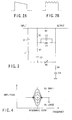
- This compensating circuit 12 includes a tilt compensating unit 121 for compensating the tilt of a frequency characteristic in a band as shown in FIG. 2A and a ripple compensating unit 122 for compensating a ripple in a band as shown in FIG. 2B, noting that these compensating units 121 and 122 are integrally structured by connecting series-parallel resonance circuits in a multi-stage configuration as shown, for example, in FIG. 3 and properly setting their Q.
- an input terminal is connected to ground through a capacitor C1, coil L1, variable resistor R5, resistor R4 and capacitor C4 and to an output terminal through a resistor R3.
- the output terminal is connected to a connection point between the variable resistor R5 and the resistor R4.
- a series circuit of the capacitor C1 and coil L1 is connected in parallel with a series circuit of a resistor R1, resistor R2 and capacitor C2 and a parallel circuit of a capacitor C3 and coil L2 is connected between a connection point of the resistors R1 and R2 and the output terminal.
- variable resistance (R5) when the variable resistance (R5) approaches 0 ⁇ , a series resonance acts due to the presence of the capacitor C1 and coil L1, so that the amplitude frequency characteristic is raised with a resonance frequency. If, on the other hand, the variable resistance (R5) goes near to infinity ( ⁇ ), a parallel resonance acts due to the presence of the capacitor C3 and coil L2, so that, the amplitude frequency characteristic is lowered with the resonance frequency. As evident from this, the amplitude level can be raised and lowered with the resonance frequency as shown in FIG. 4 and this is done by making the variable resistance (R5) variable. If an N number of such series-parallel resonance circuits are prepared and connected together in a series configuration and the resonance frequencies of the individual circuits are matched to N division frequencies in the OFDM band, it is possible to make the tilt and ripple of the frequency characteristic variable.
- the output of the compensating circuit 12 is output as an IF signal and it is also distributed by a distributor to a frequency characteristic detection circuit 14.
- the IF signal from the distributor 13 and local signal from a local signal generator 142 are mixed by a frequency converter 141 and converted to a base band signal and, after out of the converted signal a requisite bandpass signal alone is extracted by a bandpass filter (BPF) 143, and its signal level is detected by a level detector 144.
- BPF bandpass filter
- a local signal frequency of the local signal generator 142 is swept in an OFDM signal band by a local signal control circuit 145 and, by doing so, it is possible to obtain the frequency characteristic in the OFDM signal band.
- the signal level value obtained by the frequency characteristic detection circuit 14 is supplied to a compensation amount calculator 15.
- the compensation amount calculator 15 calculates an AGC control amount, tilt compensation amount and ripple compensation amount corresponding to the AGC circuit 11, tilt compensating unit 121 and ripple compensating unit 122 in accordance with the amplitude levels of the respective frequency components and output respective control signals.
- the AGC control value as shown in FIG. 5, in order to enable the margin values of a maximum value (control value MAX) and minimum value (control value MIN) of control values (an N number of them in total) for the ripple compensation to be equally distributed, that is, to enable control to be done over the whole bandpass, decision is made by finding average values, etc.
- a linearizer 16 is interposed between the compensating amount calculator 15 and the ripple compensation unit 122.
- the linearizer 16 has a reverse characteristic to the nonlinear characteristic of the ripple compensating unit 122 and converts a control signal having the linear characteristic as shown in FIG. 6A to a characteristic as shown in FIG. 6B and delivers a corresponding output to the ripple compensating unit 122. By doing so it is possible to compensate the nonlinear characteristic of the ripple compensating unit 122.
- the frequency characteristic compensator arranged in view of the fact that the signal spectrum of an OFDM signal is flat in a transmit band is characterized in that, under the condition of the amplitude being constant in its bandpass, the frequency characteristic of the transmission path and apparatus is detected. That is, since the OFDM signal should be originally flat in its bandpass, if this frequency characteristic is evaluated, it is possible to decide at which frequency the ripple occurs or where the frequency region is attenuated.
- the amplitude level of the OFDM signal frequency bandpass is found by the frequency characteristic detection circuit 14 and a frequency drooped due to the presence of the ripple or a frequency region attenuated in amplitude level is found by the compensation amount calculator 15.
- a compensating unit in the compensating circuit 12 which corresponds to the associated frequency.
- the frequency characteristic of the output OFDM signal is such that the disturbance of the frequency characteristic by the transmission path characteristic is compensated and an output is delivered in a "flat" state.
- the frequency characteristic compensator thus arranged, the transmission path characteristic varying dependent upon the seasons, weather and time involved can be properly compensated without a process of demodulation by the FFT. Further, the amount of compensation can be calculated automatically and it is easier to perform an adjusting operation of a relay device. Since the frequency characteristic of the output section is found, it is possible to compensate the frequency characteristic of the device.
- the noise component is also increased.
- a receive gain can be earned in comparison with the case where replaying is made without any compensation and there occurs no practical problem so long as the SN ratio does not exceed any allowable value.
- a compensator by the FFT processing is used in an intervening relay device and, before the SN ratio exceeds an allowable value, a transmitting signal is reconstructed, thereby eliminating a noise component. It is, therefore, possible to utilize the above-mentioned compensator in a downstream relay device.
- the compensator has been explained as being applied to a receive section's IF stage of the relay device, the present compensator is not restricted thereto and can be applied to various situations, such as applying to an RF stage.
- a compensator of a type as will be set out below has been developed so as to cancel such an echo-back.
- This compensator detects the frequency characteristic of the transmission path through the utilization of an auto-correlation and, by applying a convolution process to a received signal on the basis of this detection characteristic, a disturbing component due to the multipath reception is eliminated.
- the frequency characteristic is found by the frequency sweeping of the local signal and, in the case where there occurs any proximity multipass reception, its frequency characteristic emerges as a tilt and it is easier to achieve a multipass compensation. From this viewpoint, both the compensating units are combined together and, by utilizing the respective characteristics, it is possible to eventually improve the compensation characteristic.
- FIG. 7 shows an arrangement of a frequency characteristic compensator using the above-mentioned combination.
- Reference numeral 21 shows a first compensator unit utilizing the auto-correlation and 22 shows a second compensator unit as shown in FIG. 1. These compensator units 21 and 22 are connected in series with each other. The order of their connection is optional.
- the first compensator unit 21 receives an OFDM signal of a receive IF stage and a compensation signal from a compensation signal generation section 212 is added by an adder 211 to the IF signal and an output signal of the adder 211 is input to the compensation signal generation section 212 and to an auto-correlation processing section 213.
- the auto-correlation processing section 213 performs auto-correlation of the input signal, thereby determining the difference between the frequency characteristic of a transmission path and the frequency characteristic of a compensated signal. This difference is output, in the form of a compensation error signal, to the compensation signal generating section 212.
- the compensation signal generating section 212 is comprised of an FIR (Finite Impulse Response) filter and generates a compensated signal by cumulatively adding the compensation error signal from the auto-correlation processing section 213 to the input signal. By adding this compensated signal to the transmitting signal it is possible to compensate the frequency characteristic on the transmission path.
- FIR Finite Impulse Response
- the output of the first compensator unit 21 is supplied to the second compensator unit 22.
- the second compensator unit 22 is comprised of a counterpart as shown in FIG. 1 and its inner arrangement and processing operation are omitted.
- the first compensator unit 21 it is possible to highly accurately separate the "echo-back" of a transmitting wave and disturbing components resulting from a multipath reception from the received signal. It is not possible, however, to handle a proximity multipath reception. In this embodiment, however, the second compensator unit 22 effectively functions against the proximity multipath reception. By combining together both the compensator units 21 and 22 it is possible to obtain a "flat" frequency characteristic of the OFDM signal while suppressing not only the proximity multipath reception but also the disturbing components.
- a frequency characteristic compensator for OFDM can be provided which ensures a readier adjustment without using a process of demodulation by the FTT and can adaptively compensate the transmission path characteristic varying dependent upon the seasons, weather and time involved.
Landscapes
- Engineering & Computer Science (AREA)
- Computer Networks & Wireless Communication (AREA)
- Signal Processing (AREA)
- Power Engineering (AREA)
- Radio Relay Systems (AREA)
- Noise Elimination (AREA)
Applications Claiming Priority (2)
| Application Number | Priority Date | Filing Date | Title |
|---|---|---|---|
| JP28034599 | 1999-09-30 | ||
| JP28034599A JP3540686B2 (ja) | 1999-09-30 | 1999-09-30 | Ofdm用周波数特性補償器 |
Publications (2)
| Publication Number | Publication Date |
|---|---|
| EP1089513A1 true EP1089513A1 (fr) | 2001-04-04 |
| EP1089513B1 EP1089513B1 (fr) | 2004-02-25 |
Family
ID=17623722
Family Applications (1)
| Application Number | Title | Priority Date | Filing Date |
|---|---|---|---|
| EP19990125993 Expired - Lifetime EP1089513B1 (fr) | 1999-09-30 | 1999-12-28 | Compensateur de la charactéristique de fréquence pour OFDM |
Country Status (3)
| Country | Link |
|---|---|
| EP (1) | EP1089513B1 (fr) |
| JP (1) | JP3540686B2 (fr) |
| DE (1) | DE69915064T2 (fr) |
Cited By (2)
| Publication number | Priority date | Publication date | Assignee | Title |
|---|---|---|---|---|
| WO2008091556A1 (fr) | 2007-01-24 | 2008-07-31 | Powerwave Technologies, Inc. | Annulation d'écho adaptive destinée à un répétiteur rf sur la même fréquence utilisant un spectre de puissance pondéré |
| US8761304B2 (en) | 2009-12-17 | 2014-06-24 | Electronics And Telecommunications Research Institute | Apparatus and method for processing digital transmission/reception signals to correct in-band gain flatness |
Families Citing this family (1)
| Publication number | Priority date | Publication date | Assignee | Title |
|---|---|---|---|---|
| JP4842506B2 (ja) * | 2003-09-12 | 2011-12-21 | マスプロ電工株式会社 | 信号レベル測定装置 |
Citations (4)
| Publication number | Priority date | Publication date | Assignee | Title |
|---|---|---|---|---|
| EP0689307A1 (fr) * | 1994-06-16 | 1995-12-27 | NOKIA TECHNOLOGY GmbH | Système de radiodiffusion numérique et récepteur pour un tel système |
| EP0772310A2 (fr) * | 1995-10-30 | 1997-05-07 | British Broadcasting Corporation | Réémetteur pour signaux OFDM |
| EP0833460A2 (fr) * | 1996-09-30 | 1998-04-01 | Motorola, Inc. | Procédé et appareil pour la compensation d'ondulations dans le domaine fréquentiel pour un émetteur de communication |
| EP0869647A2 (fr) * | 1997-04-01 | 1998-10-07 | Lucent Technologies Inc. | Système de modulation multiporteuse à paramètres de fonctionnement dynamiquement réglables |
-
1999
- 1999-09-30 JP JP28034599A patent/JP3540686B2/ja not_active Expired - Fee Related
- 1999-12-28 EP EP19990125993 patent/EP1089513B1/fr not_active Expired - Lifetime
- 1999-12-28 DE DE69915064T patent/DE69915064T2/de not_active Expired - Fee Related
Patent Citations (4)
| Publication number | Priority date | Publication date | Assignee | Title |
|---|---|---|---|---|
| EP0689307A1 (fr) * | 1994-06-16 | 1995-12-27 | NOKIA TECHNOLOGY GmbH | Système de radiodiffusion numérique et récepteur pour un tel système |
| EP0772310A2 (fr) * | 1995-10-30 | 1997-05-07 | British Broadcasting Corporation | Réémetteur pour signaux OFDM |
| EP0833460A2 (fr) * | 1996-09-30 | 1998-04-01 | Motorola, Inc. | Procédé et appareil pour la compensation d'ondulations dans le domaine fréquentiel pour un émetteur de communication |
| EP0869647A2 (fr) * | 1997-04-01 | 1998-10-07 | Lucent Technologies Inc. | Système de modulation multiporteuse à paramètres de fonctionnement dynamiquement réglables |
Cited By (3)
| Publication number | Priority date | Publication date | Assignee | Title |
|---|---|---|---|---|
| WO2008091556A1 (fr) | 2007-01-24 | 2008-07-31 | Powerwave Technologies, Inc. | Annulation d'écho adaptive destinée à un répétiteur rf sur la même fréquence utilisant un spectre de puissance pondéré |
| EP2119028A4 (fr) * | 2007-01-24 | 2014-01-08 | Powerwave Technologies Inc | Annulation d'écho adaptive destinée à un répétiteur rf sur la même fréquence utilisant un spectre de puissance pondéré |
| US8761304B2 (en) | 2009-12-17 | 2014-06-24 | Electronics And Telecommunications Research Institute | Apparatus and method for processing digital transmission/reception signals to correct in-band gain flatness |
Also Published As
| Publication number | Publication date |
|---|---|
| DE69915064D1 (de) | 2004-04-01 |
| DE69915064T2 (de) | 2004-09-09 |
| EP1089513B1 (fr) | 2004-02-25 |
| JP2001103031A (ja) | 2001-04-13 |
| JP3540686B2 (ja) | 2004-07-07 |
Similar Documents
| Publication | Publication Date | Title |
|---|---|---|
| US5282023A (en) | Apparatus for NTSC signal interference cancellation through the use of digital recursive notch filters | |
| US6313738B1 (en) | Adaptive noise cancellation system | |
| US6344749B1 (en) | Test system for measuring frequency response and dynamic range on cable plant | |
| RU2542716C2 (ru) | Система связи, использующая адаптивную режекцию частоты | |
| US5325188A (en) | Apparatus for NTSC signal interference cancellation through the use of digital recursive notch filters | |
| EP0993136A1 (fr) | Emetteur | |
| JP2001053527A (ja) | 通信装置及び通信方法 | |
| US20110222591A1 (en) | Receiving circuit | |
| EP1039716A1 (fr) | Répéteur d'un signal de transmission MDFO et récepteur | |
| GB2306082A (en) | Spillover Reduction in an OFDM Repeater | |
| JP3513066B2 (ja) | Ofdm伝送信号中継装置及び受信装置 | |
| JP2010514370A (ja) | 信号干渉を決定論的に削減するための手法 | |
| JP2014204300A (ja) | 干渉波抑圧受信装置 | |
| KR101387269B1 (ko) | 데이터 전송 방법 및 데이터 전송 모뎀 | |
| US7010277B1 (en) | Arrangement and method for interference cancelling | |
| EP1089513B1 (fr) | Compensateur de la charactéristique de fréquence pour OFDM | |
| JP4046346B2 (ja) | マルチキャリア信号処理装置 | |
| US5251033A (en) | D.C. responsive equalization for television transmission channel irregularities | |
| US20080317165A1 (en) | Systems and methods of calibrating a transmitter | |
| EP0903937A2 (fr) | Système de syntonisation récepteur d'un signal de télévision numérique | |
| JP4363886B2 (ja) | 単一周波数放送波中継装置 | |
| EP0505072B1 (fr) | Indicateur de l'intensité pour un récepteur | |
| JP6404827B2 (ja) | 衛星上に設置されるように設計された無線周波数信号受信機 | |
| US20160020931A1 (en) | Method and apparatus for digitization of broadband analog signals | |
| CA2254307A1 (fr) | Methode et appareillage d'annulation du brouillage dans un modem a grande vitesse |
Legal Events
| Date | Code | Title | Description |
|---|---|---|---|
| PUAI | Public reference made under article 153(3) epc to a published international application that has entered the european phase |
Free format text: ORIGINAL CODE: 0009012 |
|
| 17P | Request for examination filed |
Effective date: 19991228 |
|
| AK | Designated contracting states |
Kind code of ref document: A1 Designated state(s): DE FR GB |
|
| AX | Request for extension of the european patent |
Free format text: AL;LT;LV;MK;RO;SI |
|
| 17Q | First examination report despatched |
Effective date: 20010719 |
|
| AKX | Designation fees paid |
Free format text: DE FR GB |
|
| GRAP | Despatch of communication of intention to grant a patent |
Free format text: ORIGINAL CODE: EPIDOSNIGR1 |
|
| GRAS | Grant fee paid |
Free format text: ORIGINAL CODE: EPIDOSNIGR3 |
|
| GRAA | (expected) grant |
Free format text: ORIGINAL CODE: 0009210 |
|
| AK | Designated contracting states |
Kind code of ref document: B1 Designated state(s): DE FR GB |
|
| REG | Reference to a national code |
Ref country code: GB Ref legal event code: FG4D |
|
| REF | Corresponds to: |
Ref document number: 69915064 Country of ref document: DE Date of ref document: 20040401 Kind code of ref document: P |
|
| ET | Fr: translation filed | ||
| PLBE | No opposition filed within time limit |
Free format text: ORIGINAL CODE: 0009261 |
|
| STAA | Information on the status of an ep patent application or granted ep patent |
Free format text: STATUS: NO OPPOSITION FILED WITHIN TIME LIMIT |
|
| 26N | No opposition filed |
Effective date: 20041126 |
|
| PGFP | Annual fee paid to national office [announced via postgrant information from national office to epo] |
Ref country code: FR Payment date: 20051208 Year of fee payment: 7 |
|
| PGFP | Annual fee paid to national office [announced via postgrant information from national office to epo] |
Ref country code: DE Payment date: 20051222 Year of fee payment: 7 |
|
| PGFP | Annual fee paid to national office [announced via postgrant information from national office to epo] |
Ref country code: GB Payment date: 20051228 Year of fee payment: 7 |
|
| PG25 | Lapsed in a contracting state [announced via postgrant information from national office to epo] |
Ref country code: DE Free format text: LAPSE BECAUSE OF NON-PAYMENT OF DUE FEES Effective date: 20070703 |
|
| GBPC | Gb: european patent ceased through non-payment of renewal fee |
Effective date: 20061228 |
|
| REG | Reference to a national code |
Ref country code: FR Ref legal event code: ST Effective date: 20070831 |
|
| PG25 | Lapsed in a contracting state [announced via postgrant information from national office to epo] |
Ref country code: GB Free format text: LAPSE BECAUSE OF NON-PAYMENT OF DUE FEES Effective date: 20061228 |
|
| PG25 | Lapsed in a contracting state [announced via postgrant information from national office to epo] |
Ref country code: FR Free format text: LAPSE BECAUSE OF NON-PAYMENT OF DUE FEES Effective date: 20070102 |