EP1089561A2 - Circuit générateur de trames d'encadrement d'image et système de télévision numérique pour son usage - Google Patents
Circuit générateur de trames d'encadrement d'image et système de télévision numérique pour son usage Download PDFInfo
- Publication number
- EP1089561A2 EP1089561A2 EP00120294A EP00120294A EP1089561A2 EP 1089561 A2 EP1089561 A2 EP 1089561A2 EP 00120294 A EP00120294 A EP 00120294A EP 00120294 A EP00120294 A EP 00120294A EP 1089561 A2 EP1089561 A2 EP 1089561A2
- Authority
- EP
- European Patent Office
- Prior art keywords
- frame
- picture
- register
- end position
- data
- Prior art date
- Legal status (The legal status is an assumption and is not a legal conclusion. Google has not performed a legal analysis and makes no representation as to the accuracy of the status listed.)
- Withdrawn
Links
- 230000004913 activation Effects 0.000 claims abstract description 5
- 230000015654 memory Effects 0.000 claims description 15
- 238000010586 diagram Methods 0.000 description 10
- 238000000034 method Methods 0.000 description 6
- 230000008859 change Effects 0.000 description 5
- 230000008569 process Effects 0.000 description 4
- 230000006870 function Effects 0.000 description 3
- 230000004044 response Effects 0.000 description 2
- 239000003086 colorant Substances 0.000 description 1
- 238000010276 construction Methods 0.000 description 1
- 230000000694 effects Effects 0.000 description 1
- 238000005516 engineering process Methods 0.000 description 1
- 230000002708 enhancing effect Effects 0.000 description 1
- 238000009432 framing Methods 0.000 description 1
- 230000004048 modification Effects 0.000 description 1
- 238000012986 modification Methods 0.000 description 1
Images




Classifications
-
- H—ELECTRICITY
- H04—ELECTRIC COMMUNICATION TECHNIQUE
- H04N—PICTORIAL COMMUNICATION, e.g. TELEVISION
- H04N5/00—Details of television systems
- H04N5/44—Receiver circuitry for the reception of television signals according to analogue transmission standards
- H04N5/445—Receiver circuitry for the reception of television signals according to analogue transmission standards for displaying additional information
- H04N5/44504—Circuit details of the additional information generator, e.g. details of the character or graphics signal generator, overlay mixing circuits
-
- H—ELECTRICITY
- H04—ELECTRIC COMMUNICATION TECHNIQUE
- H04N—PICTORIAL COMMUNICATION, e.g. TELEVISION
- H04N5/00—Details of television systems
- H04N5/44—Receiver circuitry for the reception of television signals according to analogue transmission standards
- H04N5/445—Receiver circuitry for the reception of television signals according to analogue transmission standards for displaying additional information
- H04N5/45—Picture in picture, e.g. displaying simultaneously another television channel in a region of the screen
-
- H—ELECTRICITY
- H04—ELECTRIC COMMUNICATION TECHNIQUE
- H04N—PICTORIAL COMMUNICATION, e.g. TELEVISION
- H04N21/00—Selective content distribution, e.g. interactive television or video on demand [VOD]
- H04N21/40—Client devices specifically adapted for the reception of or interaction with content, e.g. set-top-box [STB]; Operations thereof
- H04N21/43—Processing of content or additional data, e.g. demultiplexing additional data from a digital video stream; Elementary client operations, e.g. monitoring of home network or synchronising decoder's clock; Client middleware
- H04N21/431—Generation of visual interfaces for content selection or interaction; Content or additional data rendering
- H04N21/4312—Generation of visual interfaces for content selection or interaction; Content or additional data rendering involving specific graphical features, e.g. screen layout, special fonts or colors, blinking icons, highlights or animations
- H04N21/4316—Generation of visual interfaces for content selection or interaction; Content or additional data rendering involving specific graphical features, e.g. screen layout, special fonts or colors, blinking icons, highlights or animations for displaying supplemental content in a region of the screen, e.g. an advertisement in a separate window
Definitions
- This invention relates to a picture frame generating circuit and a digital television system using the picture frame generating circuit.
- the moving picture is displayed overlapping with graphics such as a still picture and a frame is formed around the moving picture.
- graphics such as a still picture and a frame is formed around the moving picture.
- the position of moving picture is to be optional.
- the size of frame is to be optional.
- JP-A-8-297481 discloses a graphic image display unit that a sub-image is framed when it is displayed in a main image.
- this display unit bit maps for frame and main image are stored in its memory. Referring to the memory simultaneously when scanning the image, if it corresponds to a frame then the frame is displayed, if to a main image then the main image is displayed, else a sub-image in its image memory is displayed.
- a capacity of memory equal to the image size is needed and a large amount of data renewal is needed when the position of frame, sub-image and main image is changed. Therefore, this display unit is not suitable for use in high resolution.
- JP-A-6-268908 (1994) discloses a multi-image frame signal generating circuit.
- this circuit in calculating the frame when multiple images line up in the horizontal direction, the comparison of frame start point and end point in the horizontal direction and the comparison of frame start point and and point in the vertical direction are conducted.
- the scan line corresponds to the start point in the horizontal direction
- the coordinates of a next frame are read from its memory.
- the scan line further goes on and corresponds to the coordinates of the next frame, the coordinates of a frame after the next are read from the memory.
- the position (coordinates) of frame is stored in RAM, and values stored in RAM are sequentially read to detect the position of frame.
- JP-A-2-02765 (1990) discloses a multi-image display control circuit. But, in this circuit, it is not clear whether the size of frame can be set or not. From the example of the specification, it is assumed that it is fixed.
- JP-A-5-204374 (1993) discloses an image display control system. Since there is no description about frame, this system simply relates to a picture-in-picture technology.
- JP-A-5-346773 (1993) discloses an overlap-display control method for multiple moving pictures.
- display area designation memories RM0, RM1, (7) are provided, Therefore, to designate a display area, amount of memory equal to the display area is required. Also, when changing the position of display image, it is necessary to rewrite a large amount of display area memory.
- Japanese patent application laid-open No.10-322619 discloses an image display unit.
- the object of this unit is to frame the main image. In framing, it is necessary to set the position of frame. Therefore, the number of values to be set increases by that much.
- a picture frame generating circuit comprises:
- a digital television system comprises:
- FIG.1 is a block diagram showing the composition of a digital television system using a picture frame generating circuit according to the invention.
- a CPU 10 writes necessary values, through a data bus 11, into registers of a display unit control circuit 14 including the picture frame generating circuit according to the invention.
- the display unit control circuit 14 based on the values, outputs switching picture data 13 stored in an image memory 12 and frame, as display data 15, to a display unit 16 such as a TV monitor.
- FIG.2 is a block diagram showing a picture frame generating circuit in the first preferred embodiment according to the invention.
- a coordinate value calculation processor 20 using calculation start signal 200 as activation signal, calculates frame start position (X) 22, frame start position (Y) 23, picture end position (X) 24, picture end position (Y) 25, frame end position (X) 26, and frame end position (Y) 27 based on picture position (X) register 30, picture position (Y) register 31, picture size (X) register 32, picture size (Y) register 33, and frame size register 34 which are written through the data bus 11. Also, frame color data are written into frame color register 35 to designate the color of frame through the data bus 11.
- the frame start position (X) 22, frame start position (Y) 23, picture end position (X) 24, picture end position (Y) 25, frame end position (X) 26, frame end position (Y) 27, picture position (X) register 30, picture position (Y) register 31, frame color data 28, picture data 13, horizontal display position 29, and vertical display position 290 are input to a selection circuit 21 of frame and picture, which selects the picture data 13 or frame color data 28 and outputs it as display data 15.
- FIG.3 is a block diagram showing the function of a preprocessor 36 of the coordinate value calculation processor 20 in FIG.2.
- the output of registers i.e., picture position (X) register 30, picture position (Y) register 31, picture size (X) register 32, picture size (Y) register 33 and frame size register 34 are input to the preprocessor 36. Then the preprocessor 36 calculates therefrom.
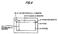
- FIG.4 shows the display-position relation among values written through the data bus 11, a picture 44 and a frame 45.
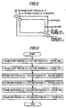
- FIG.5 shows the display-position relation among values calculated, a picture 44 and a frame 45.
- FIG.6 is a flow chart showing the calculation process by the preprocessor 36, which calculates the frame start position (X) 22, frame start position (Y) 23, picture end position (X) 24, picture end position (Y) 25, frame end position (X) 26 and frame end position (Y) 27.
- FIG.7 shows a display image 70 of framed picture 44-1 and a display image 71 of framed picture 44-2 obtained by changing the display position and size of the framed picture 44-1.
- 45-1 and 45.2 are frames.
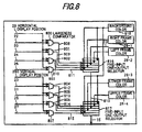
- FIG.8 is a block diagram showing a compositional example of the selection circuit 21 of frame and picture.
- 800 to 807 are largeness comparators.
- the largeness comparison results 808 to 815 become select signal for five-input one-output selectors 816 and 817.
- 819 is the output of the five-input one-output selector 816.
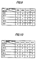
- Fig.9 shows a truth table of the five-input one-output selector 816.
- Fig.10 shows a truth table of the five-input one-output selector 817.
- FIG.11 shows an example of display in a case that the frame size varies between the upper and lower frame; and between the right and left frames.
- FIG.12 is a flow chart showing the calculation process of frame start position (X) 22, frame start position (Y) 23, picture end position (X) 24, picture end position (Y) 25, frame end position (X) 26 and frame end position (Y) 27 in FIG.3 based on the different sizes of frame.
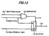
- FIG.13 is a block diagram showing an example of circuit for attaching a menu or a program table to an area for right frame color.
- 130 is a comparator and 131 is the output of the comparator 130, which outputs "1" when the comparison result coincides each other.
- 132 is a selector for switching display data 15 and menu or program table 134.
- the output 131 of the comparator 130 is "1”
- the menu or program table 134 is output as a selector output 133.
- the output 131 of the comparator 130 is "0"
- the display data 15 is output as that.
- the preprocessor 36 calculates newly six values, i.e., frame start position (X) 22, frame start position (Y) 23, picture end position (X) 24, picture end position (Y) 25, frame end position (X) 26 and frame end position (Y) 27 from picture position (X) register 30, picture position (Y) register 31, picture size (X) register 32, picture size (Y) register 33 and frame size register 34 which are written through the data bus 11.
- the largeness comparators 800 to 803 compare the frame start position (X) 22, picture position (X) register 30, picture end position (X) 24 and frame and position (X) 26 with the horizontal display position 29. When the horizontal display position 29 is larger, the largeness comparator outputs 808 to 811 are "1".
- the five-input one-output selector 816 uses the largeness comparator outputs 808 to 811 as select signal. The relation of select signal and output 819 is as shown by the truth table in FIG.9.
- the largeness comparators 804 to 807 compare the frame start position (Y) 23, picture position (Y) register 31, picture end position (Y) 25 and frame end position (Y) 27 with the vertical display position 290. When the vertical display position 290 is larger, the largeness comparator outputs 812 to 815 are "1".
- the five-input one-output selector 817 uses the largeness comparator outputs 812 to 815 as select signal.
- the relation of select signal and output 15 is as shown by the truth table in FIG.10
- the display data 15, the output of the selection circuit 21 of frame and picture, is input to the display unit 16 such as a TV monitor.
- the display unit 16 such as a TV monitor.
- the four registers of picture position (X) register 30, picture position (Y) register 31, picture size (X) register 32 and picture size (Y) register 33 are changed through the data bus 11.
- the preprocessor 36 again executes the flow chart in FIG.6, renews the frame start position (X) 22, frame start position (Y) 23, picture end position (X) 24, picture end position (Y) 25, frame end position (X) 26 and frame end position (Y) 27.
- the example of display before and after the renewal is as shown in FIG.7.
- Background color 818 in FIG.8 is a value to be set already in the display unit control circuit 14.
- Right frame color 28-1, left frame color 28-2, lower frame color 28-3 and upper frame color 28-4 are frame color data written in the frame color resister 35.
- FIG.11 shows an example of display in the case that the upper, lower, right and left frames, which are attached to the picture, are set to have different sizes.
- FIG.12 is the flow chart for calculating the frame start position (X) 22, frame start position (Y) 23, picture end position (X) 24, picture end position (Y) 25, frame end position (X) 26 and frame end position (Y) 27 in FIG.3, based on the different frame sizes.
- the difference from the flow chart in FIG.6 is only that the frame size is changed into the sizes of upper, lower, right and left frames.
- FIG.13 illustrates the third preferred embodiment of the invention. If display data 15 coincide with right frame color, the output of the comparator 130 is "1". The selector 132 outputs, instead of display data 15, the menu or program table 134 to the display unit 16 such as a TV monitor. If it is other than right frame color, the selector 132 outputs the display data 15 to the display unit 16 such as a TV monitor. In this embodiment, in attaching the menu or program table to the right side of picture, even when the position or size of picture changes, the display position of the menu or program table is changed corresponding to the change of the position or size of picture. Therefore, the menu or program table can be prevented from overlapping with or separating from the picture.
- Right frame color in the second embodiment can be changed to left frame color.
- the display position of menu or program table is changed to the left-frame side.
- Right frame color in the second embodiment can be changed to lower frame color.
- the display position of menu or program table is changed to the lower-frame side.
- Right frame color in the second embodiment can be changed to upper frame color.
- the display position of menu or program table is changed to the upper-frame side.
- changing the position of one picture can be achieved by changing only the two values of picture position (x) and picture position (Y).
- changing the size of one picture can be achieved by changing only the two values of picture size (x) and picture size (Y).
- changing the frame size of one picture can be achieved by changing only the one value of frame size.
- the usage rate of the CPU data bus can be reduced.
- the CPU data bus can be assigned to another use, thereby enhancing the function and response speed of a digital television.
- the upper, lower, right and left frames attached to a picture can be made to have different sizes, and the upper, lower, right and left frame attached to a picture can be made to have different colors.
- the size of right frame of picture is set to be an area to display the menu or program table and the color of right frame is predetermined, and there is provided the circuit for attaching the menu or program table to the color area.
- the load of CPU in real-time processing is reduced, the power of CPU can be used for the other processing by that amount reduced. As a result, the performance of the entire unit can be enhanced.
Landscapes
- Engineering & Computer Science (AREA)
- Multimedia (AREA)
- Signal Processing (AREA)
- Computer Graphics (AREA)
- Studio Circuits (AREA)
- Controls And Circuits For Display Device (AREA)
Applications Claiming Priority (2)
| Application Number | Priority Date | Filing Date | Title |
|---|---|---|---|
| JP27681499A JP2001103392A (ja) | 1999-09-29 | 1999-09-29 | 画像枠生成回路及びそれを用いたデジタルテレビシステム |
| JP27681499 | 1999-09-29 |
Publications (2)
| Publication Number | Publication Date |
|---|---|
| EP1089561A2 true EP1089561A2 (fr) | 2001-04-04 |
| EP1089561A3 EP1089561A3 (fr) | 2005-03-09 |
Family
ID=17574772
Family Applications (1)
| Application Number | Title | Priority Date | Filing Date |
|---|---|---|---|
| EP00120294A Withdrawn EP1089561A3 (fr) | 1999-09-29 | 2000-09-28 | Circuit générateur de trames d'encadrement d'image et système de télévision numérique pour son usage |
Country Status (4)
| Country | Link |
|---|---|
| US (1) | US6816202B1 (fr) |
| EP (1) | EP1089561A3 (fr) |
| JP (1) | JP2001103392A (fr) |
| CA (1) | CA2321409C (fr) |
Cited By (3)
| Publication number | Priority date | Publication date | Assignee | Title |
|---|---|---|---|---|
| EP1467558A3 (fr) * | 2003-04-11 | 2005-04-13 | Lg Electronics Inc. | Dispositif et méthode pour réaliser la fonctionnalité d'image-en-image de télévision |
| EP1469453A3 (fr) * | 2003-04-16 | 2007-01-17 | Seiko Epson Corporation | Creation d'un cadre pour dispositifs d'affichage sans utiliser de mémoire d'affichage supplémentaire |
| US8040949B2 (en) | 2003-01-09 | 2011-10-18 | The Regents Of The University Of California | Video encoding methods and devices |
Families Citing this family (4)
| Publication number | Priority date | Publication date | Assignee | Title |
|---|---|---|---|---|
| JP2004048118A (ja) * | 2002-07-08 | 2004-02-12 | Sony Corp | 画像表示装置、画像生成回路および画像生成方法 |
| US20070018999A1 (en) * | 2005-07-25 | 2007-01-25 | Rai Barinder S | Auto-centering of main image |
| US20100007791A1 (en) * | 2008-07-09 | 2010-01-14 | Mark Meister | Television display editor |
| US9746995B2 (en) * | 2011-07-14 | 2017-08-29 | Microsoft Technology Licensing, Llc | Launcher for context based menus |
Family Cites Families (20)
| Publication number | Priority date | Publication date | Assignee | Title |
|---|---|---|---|---|
| CA1212490A (fr) | 1983-04-11 | 1986-10-07 | Atlaf Rahman | Generateur de signaux de fond video |
| JPS6061794A (ja) * | 1983-09-14 | 1985-04-09 | シャープ株式会社 | 画面分割表示装置 |
| EP0194092A3 (fr) | 1985-02-25 | 1990-02-07 | Computer Graphics Laboratories, Inc. | Dispositif et méthode de visualisation |
| US4710761A (en) * | 1985-07-09 | 1987-12-01 | American Telephone And Telegraph Company, At&T Bell Laboratories | Window border generation in a bitmapped graphics workstation |
| JPS6410322A (en) * | 1987-07-03 | 1989-01-13 | Sharp Kk | Display device for picture information |
| JPH0683394B2 (ja) | 1988-09-19 | 1994-10-19 | 三洋電機株式会社 | 複画面表示制御回路及びそれを備えた映像機器 |
| US5388202A (en) * | 1990-02-02 | 1995-02-07 | Viacom International Inc. | Method and apparatus for generating window borders having pictorial frame elements |
| JPH05207368A (ja) | 1992-01-27 | 1993-08-13 | Hitachi Ltd | 重ね合わせ表示装置 |
| JPH05204374A (ja) | 1992-01-29 | 1993-08-13 | Nec Corp | 画像表示制御システム |
| JPH05346773A (ja) | 1992-06-15 | 1993-12-27 | Hitachi Ltd | マルチ動画ウインドウの重ね合わせ表示制御方法およびその装置 |
| JPH06268908A (ja) | 1993-03-10 | 1994-09-22 | Toshiba Corp | マルチ画面用枠信号発生回路 |
| US5452406A (en) * | 1993-05-14 | 1995-09-19 | Microsoft Corporation | Method and system for scalable borders that provide an appearance of depth |
| JP3379723B2 (ja) | 1993-12-07 | 2003-02-24 | 株式会社デジタル | 表示画面の重畳制御装置 |
| MY114897A (en) * | 1994-10-25 | 2003-02-28 | Thomson Consumer Electronics | Use of audio processing channel in a television receiver during a multipicture mode of operation |
| JPH08202318A (ja) * | 1995-01-31 | 1996-08-09 | Canon Inc | 記憶性を有する表示装置の表示制御方法及びその表示システム |
| JPH08297481A (ja) | 1995-04-27 | 1996-11-12 | Toshiba Corp | グラフィック画像表示装置 |
| JP3278329B2 (ja) | 1995-09-27 | 2002-04-30 | シャープ株式会社 | マルチウィンドウ表示装置およびマルチウィンドウ表示方法 |
| US6088064A (en) * | 1996-12-19 | 2000-07-11 | Thomson Licensing S.A. | Method and apparatus for positioning auxiliary information proximate an auxiliary image in a multi-image display |
| JPH10322619A (ja) | 1997-05-20 | 1998-12-04 | Fujitsu General Ltd | 映像表示装置 |
| JPH1132273A (ja) | 1997-07-10 | 1999-02-02 | Toshiba Corp | 多画面表示装置 |
-
1999
- 1999-09-29 JP JP27681499A patent/JP2001103392A/ja active Pending
-
2000
- 2000-09-28 US US09/671,151 patent/US6816202B1/en not_active Expired - Fee Related
- 2000-09-28 CA CA002321409A patent/CA2321409C/fr not_active Expired - Fee Related
- 2000-09-28 EP EP00120294A patent/EP1089561A3/fr not_active Withdrawn
Cited By (4)
| Publication number | Priority date | Publication date | Assignee | Title |
|---|---|---|---|---|
| US8040949B2 (en) | 2003-01-09 | 2011-10-18 | The Regents Of The University Of California | Video encoding methods and devices |
| EP1467558A3 (fr) * | 2003-04-11 | 2005-04-13 | Lg Electronics Inc. | Dispositif et méthode pour réaliser la fonctionnalité d'image-en-image de télévision |
| EP2202966A1 (fr) * | 2003-04-11 | 2010-06-30 | LG Electronics Inc. | Dispositif et méthode pour réaliser la fonctionnalité d'image-en-image de télévision |
| EP1469453A3 (fr) * | 2003-04-16 | 2007-01-17 | Seiko Epson Corporation | Creation d'un cadre pour dispositifs d'affichage sans utiliser de mémoire d'affichage supplémentaire |
Also Published As
| Publication number | Publication date |
|---|---|
| JP2001103392A (ja) | 2001-04-13 |
| US6816202B1 (en) | 2004-11-09 |
| EP1089561A3 (fr) | 2005-03-09 |
| CA2321409A1 (fr) | 2001-03-29 |
| CA2321409C (fr) | 2004-01-27 |
Similar Documents
| Publication | Publication Date | Title |
|---|---|---|
| JP3339284B2 (ja) | 大画面表示方式 | |
| US6469746B1 (en) | Multi-vision screen adapter | |
| EP1519358A2 (fr) | Circuit de conversion de la fréquence de trame, méthode de prévision de dépassement pour ce circuit , dispositif de commande d'affichage et dispositif d'affichage avec récepteur vidéo | |
| JP5008431B2 (ja) | 画像処理装置及び画像処理方法 | |
| JPH07322165A (ja) | 多数ビデオウィンドー同時表示方式 | |
| AU598678B2 (en) | Apparatus and method for video signal image processing under control of a data processing system | |
| WO1998040874A1 (fr) | Synthetiseur d'image, convertisseur d'image et procedes | |
| US5953019A (en) | Image display controlling apparatus | |
| EP0499462B1 (fr) | Méthode et dispositif pour contrÔler l'affichage d'images | |
| US7436544B2 (en) | Image processor | |
| EP1089561A2 (fr) | Circuit générateur de trames d'encadrement d'image et système de télévision numérique pour son usage | |
| JP2000330536A (ja) | 液晶マルチディスプレイ表示装置 | |
| US20070065010A1 (en) | Method for segmenting an image | |
| JPH03227179A (ja) | 画像データ処理装置 | |
| US20050248585A1 (en) | Image signal processing circuit and image display apparatus | |
| US6621526B1 (en) | Colorimetry converting apparatus | |
| GB2165719A (en) | Split-screen display arrangement | |
| JP3823884B2 (ja) | 大画面表示方式 | |
| JP3493126B2 (ja) | テレビジョン受信機の表示装置 | |
| JPH06124189A (ja) | 画像表示装置および画像表示制御方法 | |
| JPH0764530A (ja) | 画像表示装置の制御方式 | |
| JPH087565B2 (ja) | 画像表示装置 | |
| JP3327961B2 (ja) | 画像処理装置 | |
| JPH05252353A (ja) | 画像読み取り装置 | |
| JPH06101844B2 (ja) | 画像処理装置 |
Legal Events
| Date | Code | Title | Description |
|---|---|---|---|
| PUAI | Public reference made under article 153(3) epc to a published international application that has entered the european phase |
Free format text: ORIGINAL CODE: 0009012 |
|
| AK | Designated contracting states |
Kind code of ref document: A2 Designated state(s): AT BE CH CY DE DK ES FI FR GB GR IE IT LI LU MC NL PT SE |
|
| AX | Request for extension of the european patent |
Free format text: AL;LT;LV;MK;RO;SI |
|
| RAP1 | Party data changed (applicant data changed or rights of an application transferred) |
Owner name: NEC ELECTRONICS CORPORATION |
|
| PUAL | Search report despatched |
Free format text: ORIGINAL CODE: 0009013 |
|
| AK | Designated contracting states |
Kind code of ref document: A3 Designated state(s): AT BE CH CY DE DK ES FI FR GB GR IE IT LI LU MC NL PT SE |
|
| AX | Request for extension of the european patent |
Extension state: AL LT LV MK RO SI |
|
| 17P | Request for examination filed |
Effective date: 20050126 |
|
| AKX | Designation fees paid |
Designated state(s): DE FR GB |
|
| STAA | Information on the status of an ep patent application or granted ep patent |
Free format text: STATUS: THE APPLICATION HAS BEEN WITHDRAWN |
|
| 18W | Application withdrawn |
Effective date: 20080227 |