EP1089563B1 - Vorrichtung zur Bewegungskompensation für digitale Videoformat-Abwärtskonvertierung - Google Patents
Vorrichtung zur Bewegungskompensation für digitale Videoformat-Abwärtskonvertierung Download PDFInfo
- Publication number
- EP1089563B1 EP1089563B1 EP20000308454 EP00308454A EP1089563B1 EP 1089563 B1 EP1089563 B1 EP 1089563B1 EP 20000308454 EP20000308454 EP 20000308454 EP 00308454 A EP00308454 A EP 00308454A EP 1089563 B1 EP1089563 B1 EP 1089563B1
- Authority
- EP
- European Patent Office
- Prior art keywords
- section
- sequence
- coefficient
- pixels
- data set
- Prior art date
- Legal status (The legal status is an assumption and is not a legal conclusion. Google has not performed a legal analysis and makes no representation as to the accuracy of the status listed.)
- Expired - Lifetime
Links
Images


Classifications
-
- H—ELECTRICITY
- H04—ELECTRIC COMMUNICATION TECHNIQUE
- H04N—PICTORIAL COMMUNICATION, e.g. TELEVISION
- H04N19/00—Methods or arrangements for coding, decoding, compressing or decompressing digital video signals
- H04N19/40—Methods or arrangements for coding, decoding, compressing or decompressing digital video signals using video transcoding, i.e. partial or full decoding of a coded input stream followed by re-encoding of the decoded output stream
-
- H—ELECTRICITY
- H04—ELECTRIC COMMUNICATION TECHNIQUE
- H04N—PICTORIAL COMMUNICATION, e.g. TELEVISION
- H04N19/00—Methods or arrangements for coding, decoding, compressing or decompressing digital video signals
- H04N19/48—Methods or arrangements for coding, decoding, compressing or decompressing digital video signals using compressed domain processing techniques other than decoding, e.g. modification of transform coefficients, variable length coding [VLC] data or run-length data
-
- H—ELECTRICITY
- H04—ELECTRIC COMMUNICATION TECHNIQUE
- H04N—PICTORIAL COMMUNICATION, e.g. TELEVISION
- H04N19/00—Methods or arrangements for coding, decoding, compressing or decompressing digital video signals
- H04N19/50—Methods or arrangements for coding, decoding, compressing or decompressing digital video signals using predictive coding
- H04N19/503—Methods or arrangements for coding, decoding, compressing or decompressing digital video signals using predictive coding involving temporal prediction
- H04N19/51—Motion estimation or motion compensation
-
- H—ELECTRICITY
- H04—ELECTRIC COMMUNICATION TECHNIQUE
- H04N—PICTORIAL COMMUNICATION, e.g. TELEVISION
- H04N19/00—Methods or arrangements for coding, decoding, compressing or decompressing digital video signals
- H04N19/50—Methods or arrangements for coding, decoding, compressing or decompressing digital video signals using predictive coding
- H04N19/59—Methods or arrangements for coding, decoding, compressing or decompressing digital video signals using predictive coding involving spatial sub-sampling or interpolation, e.g. alteration of picture size or resolution
-
- H—ELECTRICITY
- H04—ELECTRIC COMMUNICATION TECHNIQUE
- H04N—PICTORIAL COMMUNICATION, e.g. TELEVISION
- H04N19/00—Methods or arrangements for coding, decoding, compressing or decompressing digital video signals
- H04N19/90—Methods or arrangements for coding, decoding, compressing or decompressing digital video signals using coding techniques not provided for in groups H04N19/10-H04N19/85, e.g. fractals
-
- H—ELECTRICITY
- H04—ELECTRIC COMMUNICATION TECHNIQUE
- H04N—PICTORIAL COMMUNICATION, e.g. TELEVISION
- H04N7/00—Television systems
- H04N7/01—Conversion of standards, e.g. involving analogue television standards or digital television standards processed at pixel level
- H04N7/0125—Conversion of standards, e.g. involving analogue television standards or digital television standards processed at pixel level one of the standards being a high definition standard
-
- H—ELECTRICITY
- H04—ELECTRIC COMMUNICATION TECHNIQUE
- H04N—PICTORIAL COMMUNICATION, e.g. TELEVISION
- H04N7/00—Television systems
- H04N7/01—Conversion of standards, e.g. involving analogue television standards or digital television standards processed at pixel level
- H04N7/0135—Conversion of standards, e.g. involving analogue television standards or digital television standards processed at pixel level involving interpolation processes
- H04N7/0137—Conversion of standards, e.g. involving analogue television standards or digital television standards processed at pixel level involving interpolation processes dependent on presence/absence of motion, e.g. of motion zones
-
- H—ELECTRICITY
- H04—ELECTRIC COMMUNICATION TECHNIQUE
- H04N—PICTORIAL COMMUNICATION, e.g. TELEVISION
- H04N5/00—Details of television systems
- H04N5/44—Receiver circuitry for the reception of television signals according to analogue transmission standards
- H04N5/445—Receiver circuitry for the reception of television signals according to analogue transmission standards for displaying additional information
- H04N5/45—Picture in picture, e.g. displaying simultaneously another television channel in a region of the screen
Definitions
- the invention is applicable to the implementation of a digital video format down-conversion for use in digital video decoder.
- Typical applications of this invention include HDTV decoding, video conferencing and picture-in-picture systems.
- Low-resolution digital video decoders have received considerable attention lately in academia and industry.
- the format down-conversion can be achieved by decimating the decoded full-resolution video sequences. Reconstructed video with good quality can be obtained by using this method.
- the decimation of decoded video sequences adds complexity to the full-resolution video decoding.
- image decimation has to be realized in the earlier stage of the decoder, for example, inside the decoding loop.
- EP0707426A a digital video decoder that provides format down-conversion with motion-compensation is disclosed. Motion compensation is achieved by first interpolating, then performing full-resolution motion compensation, and finally, decimation of the compensated output.
- European patent application EP0786902A discusses a technique for changing image resolution using a direct discrete cosine transformation (DCT) mapping, whereby DCT coefficient values of an original resolution are mapped to converted coefficient values of a new resolution, without having to convert the original DCT coefficient values into pixels first.
- DCT direct discrete cosine transformation
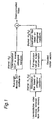
- Fig. 1 shows a block diagram of this video format down-conversion method. The details of the system operation and the orthogonal kernels were discussed in the above-mentioned application.
- the low-resolution pixels stored in the frame buffer are interpolated and decimated using orthogonal transform basis functions before and after the full-resolution motion compensation.
- the interpolation and decimation filters play a very important role in controlling the error propagation introduced by picture decimation of the format down-conversion system of digital video.
- these filters are realized using a number of orthogonal transform kernels.
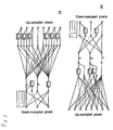
- One example for the orthogonal transform kernels used for video down-conversion with the decimation ratio of 8:3 are illustrated in Fig. 2.
- the direct computation architecture of the interpolation and decimation filtering operations based on these kernels are shown in Fig. 3. Since the coefficients of the kernels are simple, the implementation of the system is relatively easy compared to the conventional digital video format down-conversion methods. Simulation results show that this method is also very effective in error propagation control.
- the digital video format down-conversion method using orthogonal transform described in the prior art generates high quality down-converted video.
- the transform kernels consist of simple coefficients
- a more efficient implementation method for efficient computation of the orthogonal transforms is still needed in order for the system to handle high bit rate video decoding, such as HDTV decoding.
- the problem to be solved by the current invention is to establish efficient computation architecture for the interpolation and decimation filtering processes to achieve effective motion compensation for the digital video format down-conversion system mentioned in the prior art.
- US 4 768 159 discloses an efficient computation method for discrete Fourier transform.
- the invention is defined by claim 1.
- the computation architecture comprises a frequency component computing section, a coefficient weighting section and a pixel reconstruction section. Less computational operations are required compared to the direct implementation of the orthogonal transform kernels described in the prior art.
- the frequency component computing section is used to transform the input into frequency domain to generate the transform coefficients.
- the coefficient weighting section is used for receiving transform coefficients and generating weighted transform coefficients.
- the weighted transform coefficients are finally transformed into spatial domain to generate the filtered pixels having different resolution from the original pixels.
- the operation of the computation architecture for the interpolation and decimation filtering processes is now explained.
- the original pixels are transformed into frequency domain by the frequency component computing section to generate the transform coefficients.
- the transform coefficients are multiplied by a set of pre-determined constants by the coefficient weighting section to generate the weighted transform coefficients.
- the weighted transform coefficients are transformed from frequency domain into spatial domain by the pixel reconstruction section to provide filtered pixels which have different resolution from the original pixels.
- a reversed sequence of a block of the original pixels is generated in upper or lower address reversed order.
- a pair of selected pixel sequences is selected from the pixel sequence, the reversed sequence, the transform coefficients and the bit-shifted coefficient sequence by a pixel selecting section.
- An operation indication sequence is generated by the pixel selecting section to indicate the adding or subtracting operation.
- the sum or difference of the pair of selected pixel sequences is computed based on the operation indication sequence to generate the transform coefficients.
- Each transform coefficient is shifted by one or more bits to generate the bit-shifted coefficient sequence.
- the frequency component computing section can also be operated using another method described here.
- the data address reversing section provides a reversed data set of a block of the original pixels in upper or lower address reversed order.
- a data selecting section receives the original pixels and the reversed data set to provide an operation indication set and two selected data sets.
- the calculator computes sum or difference of each pair of the selected data to generate processed data.
- One or more cascaded arithmetic units receives the processed data, manipulates them algebraically to provide the transform coefficients.
- Each transform coefficient is multiplied by one of the pre-determined constant values stored in the coefficient memory.
- the output of the multiplying section or the transform coefficients are switched based on a coefficient bypass control signal to provide the weighted transform coefficients.
- the coefficient bypass control signal is determined based on the transform kernels used for the format down-conversion system of digital video.
- the operations of the pixel reconstruction section are now explained.
- the weighted transform coefficients are shifted by one or more bits to generate the bit-shifted vector.
- a pair of selected coefficient vectors is selected from the coefficient vector, the bit-shifted vector, filtered pixels and reversed pixel vector by a coefficient selecting section.
- An operation indication vector is generated by the coefficient selecting section to indicate the adding or subtracting operation.
- the sum or difference of the pair of coefficient samples is computed based on the operation indication vector to generate the filtered pixels.
- the reversed pixel vector of a block of filtered coefficients is generated by an address reversing section in upper or lower address reversed order.
- the pixel reconstruction section can also be realized using one or more cascaded arithmetic units.
- the shifter shifts the input data by one or more bits to generate bit-shifted data set.
- the data selector receives the input data and the bit-shifted data set to provide an operation indication set and two selected data sets.
- a calculator adds or subtracts two selected data sets based on the operation indication.
- the input terminal of the frequency component computing section can be coupled to the output terminal of the frame buffer, and the output terminal of the pixel reconstruction section can provide the interpolated pixels to the motion compensation section.
- the input terminal of the frequency component computing section can be coupled to the output terminal of the motion compensation section, and the output terminal of the pixel reconstruction section can provide the decimated pixels to the adding section.
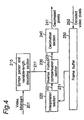
- FIG. 4 illustrates the block diagram of an efficient motion compensation system for digital video format down-conversion.
- the system comprises a syntax parser and variable-length decoding section 210, an interpolation section 220, an inverse motion compensation section 230, a decimation section 240 and a frame buffer 250.
- the interpolation section 220 and the decimation section 240 are used before and after the inverse motion compensation section 230.
- the video bit stream 201 is first decoded by the syntax parser and variable-length decoding section 210 to obtain the decoded motion parameters 211.
- the frame buffer 250 stores low-resolution video pictures.
- the low-resolution reference pixels 251 are retrieved from the frame buffer 250 by the interpolation section 220 and interpolated to generate the interpolated pixels 221 for inverse motion compensation section 230.
- the inverse motion compensation section 230 performs half-pel motion compensation based on the interpolated pixels 221 and the decoded motion parameters 211 to obtain the motion-compensated pixels 231.
- the motion-compensated pixels 231 are then decimated by the decimation section 240 to generate decimated pixels 241.
- the effect of this embodiment is that the accuracy of inverse motion compensation for down-converted video can be improved by introducing the interpolation section and the decimation section. Since the format down-conversion processing of each video frame introduces error, it is extremely important to control the propagation of decoding errors.
- the properly designed interpolation section and decimation section are efficient error control engines for minimizing the error of each decoded frame.
- FIG. 5 explains the method used in the interpolation and decimation section illustrated in Fig. 4. It comprises a frequency component computing section 300, a coefficient weighting section 310 and a pixel reconstruction section 320.
- the operation of this embodiment is now explained.
- the original pixels 301 retrieved from the frame buffer 270 are transformed into transform coefficients 302 by frequency component computing section 300.
- the transform coefficients 302 are multiplied by the pre-determined values to generate weighted transform coefficients 311 using the coefficient weighting section 310.
- the weighted transform coefficients 311 are transformed, by the pixel reconstruction section 320, into spatial domain to generate the filtered pixels 321 having different resolution from the original pixels 301.
- FIG. 6 Another embodiment shown in Fig. 6 explains the realization of the frequency component computing section 300 illustrated in Fig. 5.
- This apparatus comprises an address reversing section 400, a pixel selecting section 410, a calculator 420 which functions as an adder and/or subtractor to produce sum/difference and a bit shifting section 430.
- the reversed sequence 402 of a block of the original pixels 401 are generated in upper or lower address reversed order by the address reversing section 400.
- a pair of selected pixel sequences 412, 413 is selected from the original pixels 401, reversed sequence 402, transform coefficients 421 and bit-shifted coefficient sequence 431 by a pixel selecting section 410.
- An operation indication sequence 411 is also generated by the pixel selecting section 410 to indicate the adding or subtracting operation.
- the sum or difference of the pair of selected pixel sequences 412, 413 is computed based on the operation indication sequence 411 to generate the transform coefficients 421.
- Each transform coefficient 421 is shifted by one or more bits by the bit shifting section 430 to generate the bit-shifted coefficient sequence 431.
- FIG. 7 Another embodiment shown in Fig. 7 explains the details of the coefficient weighting section 310 shown in Fig. 5.
- This apparatus comprises a coefficient memory 500, a multiplying section 510 and a multiplexer 520.
- Each transform coefficient 511 is multiplied by one of the pre-determined constant values stored in the coefficient memory 500.
- the output of multiplying section 510 and the transform coefficients 511 are multiplexed based on a coefficient bypass control signal 522 to provide the weighted transform coefficients 521.
- the coefficient bypass control signal is determined based on the transform kernels used for the format down-conversion system of digital video.
- FIG. 8 Another embodiment shown in Fig. 8 explains the details of the pixel reconstruction section 320 shown in Fig. 5.
- This apparatus comprises a bit shifting section 600, a coefficient selecting section 610, a calculator 620 serving as an adder and/or subtractor and an address reversing section 630.
- the weighted transform coefficients 601 are shifted by one or more bits, by the bit shifting section 600 to generate the bit-shifted vector 602.
- a pair of selected coefficient vectors 612, 613 is selected from the weighted transform coefficients 601, bit-shifted vector 602 and filtered pixels 621 by the signal selecting section 610.
- An operation indication vector 611 is also generated by the coefficient selecting section 610 to indicate the adding or subtracting operation.
- the sum or difference of the selected coefficient vectors 612, 613 is computed based on the operation indication vector 611 to generate the filtered pixels 621.
- the immediate effect of the embodiments shown in Fig. 5 through Fig. 8 is that an image interpolation and decimation apparatus can be realized using efficient computation architecture derived according to the properties of generalized orthogonal transforms. Same apparatus can be used for both interpolation and decimation filtering processes derived based on orthogonal transforms. The intermediate computation results are fed back to a signal selecting section for further processing using same circuit.
- another effect of the embodiment shown in Fig. 5 through Fig. 8 is that it is possible to reduce the scale of the circuits required for format down-conversion system of digital video.
- FIG. 9 explains another apparatus for implementation of the interpolation and decimation filtering processes.
- This apparatus comprises a pre-processing section 710, two sets of cascaded arithmetic units 720, 740 and coefficient weighting section 730.
- the original pixels 701 are processed by the pre-processing section 710 to generate processed data 711.
- the processed data 711 is further processed by one set of cascaded arithmetic units 720 to generate the transform coefficients 721 which is the same as the transform coefficients 302 shown in Fig. 5.
- the coefficient weighting section 730 performs the same operation described in the embodiment shown in Fig. 5 on the transform coefficients 721 and provides the weighted transform coefficients 731.
- Another set of cascaded arithmetic units receives the weighted transform coefficients 731 and processes them to generate the filtered pixel 741.
- the embodiment shown in Fig. 10 explains the details of the pre-processing section used in the embodiment illustrated in Fig. 9. It comprises a data selector 810, a data address reversing section 820 and a calculator 830 for adding and subtracting.
- the reversed data set 821 of a block of original pixels 801 is generated in upper or lower address reversed order by the data address reversing section 820.
- the data selector 810 chooses a pair of data 812, 813, from the original pixels 801 and the reversed data set 821, and generates an operation indication data 811.
- the operation indication data 811 is a binary data with one value indicating adding operation and another value indicating subtracting operation.
- the calculator 830 computes the sum or difference of the selected pair of data 812, 813 based on the operation indicator 811 to generate the processed data 831.
- FIG. 11 Another embodiment shown in Fig. 11 explains the details of the cascaded arithmetic units.
- the 1st arithmetic unit 900 through the nth arithmetic unit 910, n ⁇ 1, are connected with each other in a cascaded way.
- the nth arithmetic unit 910 comprises a shifter 920, a data selector 930 and a calculator 940 for adding and subtracting.
- the operation of the nth (n ⁇ 1) arithmetic unit 910 is now explained.
- the data selector 930 chooses a pair of data (d 1n and d 2n ), from r n-1 and S n , and an operation indicator (op n ).
- the operation indicator (op n ) is a binary data with one value indicating adding operation and another indicating subtracting operation.
- the calculator 940 computes the sum or difference of d 1n and d 2n based on the value of op n to generate the output r n of the nth arithmetic unit 910.
- FIG. 9 The effect of the embodiments shown in Fig. 9 through Fig. 11 is that it provides an alternative way to implement the interpolation and decimation filtering processing. Similar to the embodiments shown in Fig. 5 through Fig. 8, same architecture can be used for both interpolation and decimation filtering processing derived based on orthogonal transforms. However, there is no feedback loop in each embodiment. Thus, the latency of introduced by the interpolation and decimation circuits can be minimized at the cost of more hardware requirements.
- a computation architecture which is built based on the apparatus described in the embodiments shown in Fig. 9 through Fig. 11, for the purpose of video format down-conversion using the orthogonal transform kernels presented in Fig. 2 of this patent specification is illustrated in Fig. 12.
- K 0 is used for inverse orthogonal transform.
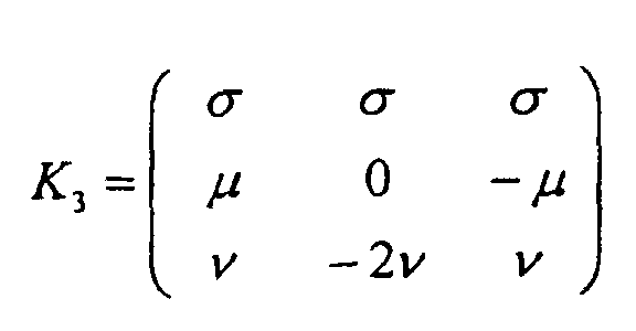
- K 1 and K 2 are used for interpolation processing while K 3 and K 4 are used for decimation processing. It is clear that compared to the direct implementation of the interpolation and decimation filter realized using the orthogonal transform presented in the prior art (see Fig. 3), the number of shifting and adding operations can be reduced by 46% and 21%, respectively.
- This invention produces high-quality video format down-conversion solution.
- the computational requirement of the invention is much less intensive than that required for the conventional low-resolution video decoding methods or the direct implementation of the digital video format down-conversion method mentioned in the prior art.
- the apparatus designed for interpolation filter and decimation filter are of the same architecture.
- the number of shifting and adding operations required by the interpolation and decimation can be reduced by 46% and 21%, respectively, for the video format down-conversion at the down-conversion ratio of 8:3.
Landscapes
- Engineering & Computer Science (AREA)
- Multimedia (AREA)
- Signal Processing (AREA)
- Compression Or Coding Systems Of Tv Signals (AREA)
- Television Systems (AREA)
- Image Processing (AREA)
- Compression, Expansion, Code Conversion, And Decoders (AREA)
Claims (19)
- Vorrichtung zum Durchführen einer leistungsfähigen Interpolations- und Dezimierungsberechnung zur Bewegungskompensation bei der Abwärtskonvertierung eines digitalen Videoformates, mit :einem Frequenzkomponenten-Berechnungsteil (300) mit einem Eingangsanschluss zum Empfangen eines Blockes mit Originalpixeln (301), Transformieren der Originalpixel in den Frequenzbereich und Bereitstellen von Transformationskoeffizienten (302, 721);einem Koeffizienten-Gewichtungsteil (310, 730) zum Empfangen der Transformationskoeffizienten (302, 721) und Multiplizieren jedes der Transformationskoeffizienten mit einem von einem Satz vorbestimmter konstanter Werte, um einen gewichteten Transformationskoeffizienten (311, 731) zu erzeugen; undeinen Pixelrekonstruktionsteil (320) mit einem Eingangsanschluss zum Empfangen des gewichteten Transformationskoeffizienten (311, 731) und einem Ausgangsanschluss zum Erzeugen von gefilterten Pixeln (321, 741), die eine von den Originalpixeln (301) verschiedene Auflösung besitzen,gekennzeichnet dadurch, dass die Transformationskoeffizienten in Übereinstimmung mit einer verallgemeinerten orthogonalen Transformation bereit gestellt werden, welche Kerne aufweist, die wie folgt definiert sind:


- Vorrichtung gemäß Anspruch 1, wobei der Eingangsanschluss des Frequenzkomponenten-Berechnungsteils (300) mit einem Ausgangsanschluss eines Bildzwischenspeichers (250, 270) verbunden ist und der Ausgangsanschluss des Pixelrekonstruktionsteils (320) einem inversen Bewegungs-Kompensationsteil (230) interpolierte Pixel (221) bereitstellt.
- Vorrichtung gemäß Anspruch 1, wobei der Eingangsanschluss des Frequenzkomponenten-Berechnungsteils (300) mit einem Ausgangsanschluss eines inversen Bewegungs-Kompensationsteils (230) verbunden ist und der Ausgangsanschluss des Pixelrekonstruktionsteils (320) dezimierte Pixel (241) bereitstellt.
- Vorrichtung gemäß Anspruch 1, wobei der Frequenzkomponenten-Berechnungsteil (300) weiter aufweist:einen Adressumkehrteil (400) zum Bereitstellen einer umgekehrten Folge (402) eines Blocks von Originalpixeln (401) mit umgekehrter Reihenfolge in der oberen Adresse;ein Bit-Schiebeteil (430) zum Schieben jedes der Transformationskoeffizienten (421, 312) um ein oder mehrere Bits, um eine Bit-verschobene Koeffizientenfolge (431) zu erzeugen;einen Pixelauswahlteil (410) zum Empfangen der Originalpixel (401), der umgekehrten Folge (402), der Transformationskoeffizienten (421, 302) und der Bit-verschobenen Koeffizientenfolge (431) und zum Bereitstellen einer Betriebsanzeigenfolge (411), einer ersten ausgewählten Pixelfolge (412) und einer zweiten ausgewählten Pixelfolge (413); undeinem Rechner (420) zum Empfangen der Betriebsanzeigenfolge (411), der ersten ausgewählten Pixelfolge (412) und der zweiten ausgewählten Pixelfolge (413), und zum Berechnen zumindest eines von einer Summe und einer Differenz von jedem Paar einer Pixelauswahl, einem aus der ersten ausgewählten Pixelfolge (412) und dem anderen aus der zweiten ausgewählten Pixelfolge (413), basierend auf der Betriebsanzeigefolge (411), um die Transformationskoeffizienten (421, 302) zu erzeugen.
- Vorrichtung gemäß Anspruch 1, wobei der Frequenzkomponenten-Berechnungsteil (300) weiter aufweist:einen Adressumkehrteil (400) zum Bereitstellen einer umgekehrten Folge (402) eines Blocks von Originalpixeln (401) mit umgekehrter Reihenfolge in der unteren Adresse;einen Bit-Schiebeteil (430) zum Schieben jeder der Transformationskoeffizienten (421, 312) um ein oder mehrere Bits, um eine Bit-verschobene Koeffizientenfolge (431) zu erzeugen;einen Pixelauswahlteil (410) zum Empfangen der Originalpixel (401), einer umgekehrten Folge (402), den Transformationskoeffizienten (421, 302) und der Bit-verschobenen Koeffizientenfolge (431) und zum Bereitstellen einer Betriebsanzeigefolge (411), einer ersten ausgewählten Pixelfolge (412) und einer zweiten ausgewählten Pixelfolge (413);einem Rechner (420) zum Empfangen der Betriebsanzeigefolge (411), der ersten ausgewählten Pixelfolge (412) und der zweiten ausgewählten Pixelfolge (413); und zum Berechnen zumindest eines von einer Summe und einer Differenz von jedem Paar einer Pixelauswahl, einem aus der ersten ausgewählten Pixelfolge (412) und der anderen aus der zweiten ausgewählten Pixelfolge (413), basierend auf der Betriebsanzeigefolge (411), um die Transformationskoeffizienten (421, 302) zu erzeugen.
- Vorrichtung gemäß Anspruch 1, wobei der Koeffizienten-Gewichtungsteil (310) weiter aufweist:einen Koeffizientenspeicher (500) zum Speichern vorbestimmter konstanter Werte;einem Multiplikationsteil (510) mit einem Eingabeanschluss zum Empfangen der Transformationskoeffizienten (511, 302) und zum Multiplizieren von einem der Transformationskoeffizienten mit einem von den vorbestimmten konstant Werten, die in dem Koeffizientenspeicher (500) gespeichert sind; undeinem Multiplexer (520) zum Auswählen entweder der Ausgabe des Multiplikationsteils (510) oder der Transformationskoeffizienten (511, 302), basierend auf einem Koeffizientenbypass-Steuerungssignal (522), um die gewichteten Transformationskoeffizienten (521, 311) bereitzustellen.
- Vorrichtung gemäß Anspruch 1, wobei der Pixelrekonstruktionsteil (320) weiter aufweist:ein Bit-Schiebeteil (600) zum Schieben jedes der gewichteten Transformationskoeffizienten (601, 311) um ein oder mehrere Bits, um einen Bit-verschobenen Vektor (602) zu erzeugen;einen Koeffizienten-Auswahlteil (610) zum Empfangen der gewichteten Transformationskoeffizienten (601, 311), des Bit-verschobenen Vektors (602) und der gefilterten Pixel (321) und zum Bereitstellen eines Betriebsanzeigevektors (611), eines ersten ausgewählten Koeffizientenvektors (612) und eines zweiten ausgewählten Koeffizientenvektors (613); undeinem Rechner (620) zum Empfangen des Betriebsanzeigevektors (611), des ersten ausgewählten Koeffizientenvektors (612) und des zweiten ausgewählten Koeffizientenvektors (613); und zum Berechnen zumindest eines von einer Summe und einer Differenz von jedem Paar einer Koeffizientenauswahl, wobei einer von dem ersten ausgewählten Koeffizientenvektor (612) und der andere von dem zweiten ausgewählten Koeffizientenvektor (613) ausgewählt ist, basieren auf dem Betriebsanzeigevektor (611), um die gefilterten Pixel (621, 321) zu erzeugen.
- Vorrichtung gemäß Anspruch 1, wobei der Frequenzkomponenten-Berechnungsteil (300) aufweist:ein Vorverarbeitungsteil (710) zum Empfangen der Originalpixel (701, 301), zum Verändern dieser in algebraischer Weise, um verarbeitete Daten (711) bereitzustellen; undeinen oder mehrere hintereinander geschaltete arithmetische Einheiten (720, 740) die einen Eingangsanschluss und einen Ausgangsanschluss aufweisen.
- Vorrichtung gemäß Anspruch 8, wobei der Eingangsanschluss von der ersten hintereinander geschalteten arithmetischen Einheit (720) mit dem Vorverarbeitungsteil (710) verschaltet ist.
- Vorrichtung gemäß Anspruch 8, wobei der Eingangsanschluss der m-ten (m>1) hintereinander geschalteten arithmetischen Einheit (740) mit dem Ausgangsanschluss von der (m-1)-ten hintereinander geschalteten arithmetischen Einheit (720) verschaltet ist.
- Vorrichtung gemäß Anspruch 8, wobei der Ausgangsanschluss der letzten hintereinander geschalteten arithmetischen Einheit (740) dem Koeffizienten-Gewichtungsteil (730) die Transformationskoeffizienten (721) bereitstellt.
- Vorrichtung gemäß Anspruch 8, wobei der Vorverarbeitungsteil (710) weiter aufweist:einen Adressdatenumkehrteil (820) zum Bereitstellen eines umgekehrten Datensatzes (821) mit einem Block mit Originalpixeln (801, 301) mit umgekehrter Reihenfolge in der oberen Adresse;einem Datenauswahlteil (801) zum Empfangen der Originalpixel (801, 301) und des umgekehrten Datensatzes (821) und zum Bereitstellen eines Betriebsanzeigesatzes (811), eines ersten ausgewählten Datensatzes (812) und eines zweiten ausgewählten Datensatzes (813); undeinem Rechner (830) zum Empfangen des Betriebsanzeigesatzes (811), des ersten ausgewählten Datensatzes (812) und des zweiten ausgewählten Datensatzes (813), und zum Berechnen einer Summe/Differenz jedes Datenpaars, eines aus dem ersten ausgewählten Datensatz (812) und das andere aus dem zweiten ausgewählten Datensatz (813), basierend auf dem Betriebsanzeigesatz (810), um die verarbeiteten Daten (711) zu erzeugen.
- Vorrichtung gemäß Anspruch 8, wobei der Vorverarbeitungsteil (710) weiter aufweist:ein Adressdatenumkehrteil (820) zum Bereitstellen eines umgekehrten Datensatzes (821) aus einem Block mit Originalpixeln (801, 301) mit umgekehrter Reihenfolge in der niedrigen Adresse;einem Datenauswahlteil (801) zum Empfangen der Originalpixel (801, 301) und des umgekehrten Datensatzes (821) und zum Bereitstellen eines Betriebsanzeigesatzes (811), eines ersten ausgewählten Datensatzes (812) und eines zweiten ausgewählten Datensatzes (813); undeinem Rechner (830) zum Empfangen des Betriebsanzeigesatzes (811), des ersten ausgewählten Datensatzes (812) und des zweiten ausgewählten Datensatzes (813), und zum Berechnen einer Summe/Differenz jedes Datenpaars, eines aus dem ersten ausgewählten Datensatz (812) und das andere aus dem zweiten ausgewählten Datensatz (813), basierend auf dem Betriebsanzeigesatz (811), um die verarbeiteten Daten (711) zu erzeugen.
- Vorrichtung gemäß Anspruch 1, wobei der Pixelrekonstruktionsteil (320) weiter eine oder mehrere hintereinandergeschaltete arithmetische Einheiten aufweist, die einen Eingangsanschluss und einen Ausgangsanschluss besitzen.
- Vorrichtung gemäß Anspruch 14, wobei der Eingangsanschluss von der ersten hintereinander geschalteten arithmetischen Einheit mit dem Koeffizienten-Gewichtungsteil verschaltet ist.
- Vorrichtung gemäß Anspruch 14, wobei der Eingangsanschluss der m-ten (m>1) hintereinander geschalteten arithmetischen Einheit mit dem Ausgangsanschluss der (m-1)-ten hintereinander geschalteten Einheit verschaltet ist.
- Vorrichtung gemäß Anspruch 14, wobei der Ausgangsanschluss der letzten hintereinander geschalteten arithmetischen Einheit die gefilterten Pixel bereitstellt.
- Vorrichtung gemäß Anspruch 8 oder Anspruch 14, wobei die n-te (n≥1) hintereinandergeschaltete arithmetischen Einheit (910) aufweist:einen Schieber (920) zum Schieben der Eingangsdaten (rn-1) um ein oder mehrere Bits, um einen Bit-verschobenen Datensatz (Sn) zu erzeugen;einen Datenauswähler (930) zum Empfangen der Eingangsdaten (rn-1) und des Bit-verschobenen Datensatzes (Sn) und Bereitstellen eines Betriebsanzeigesatzes (opn), eines ersten ausgewählten Datensatzes und eines zweiten ausgewählten Datensatzes; undeinem Rechner (940) zum Empfangen des Betriebsanzeigesatzes (opn), des ersten ausgewählten Datensatzes und des zweiten ausgewählten Datensatzes, und zum Addieren/Subtrahieren von zwei der ausgewählten Datensätzen (d1nd2n), wobei basierend auf dem Betriebsanzeigesatz (opn), wobei einer aus dem ersten ausgewählten Datensatz und der andere aus dem zweiten ausgewählten Datensatz ausgewählt ist, und zum Bereitstellen der Ausgabe der hintereinander geschalteten arithmetischen Einheit (rn).
- Vorrichtung zum Durchführen einer leistungsfähigen Bewegungskompensation für eine Abwärtswandlung eines digitalen Videoformates, wobei eine verallgemeinerte orthogonale Transformation verwendet wird, mit:wobei zumindest einer von dem Interpolationsteil (220) und dem Dezimierungsteil (240) eine Vorrichtung gemäß einem der vorhergehenden Ansprüche aufweist.einem Syntaxparser und einem Decodierungsteil mit variabler Länge (210) zum Decodieren eines Videobitstroms (201), der einen Ausgangsanschluss zum Bereitstellen decodierter Bewegungsparameter (211) besitzt;einem Bildzwischenspeicher (250) zum Speichern rekonstruierter niedrigaufgelöster Bilder und aufweisend einen Ausgangsanschluss zum Bereitstellen niedrigaufgelöster Bezugspixel (251);einem Interpolationsteil (220) zum Abbilden aus dem Bildzwischenspeicher (250) abgerufener niedrigaufgelöster Bezugspixel (251) auf einen hochaufgelösten Raum und zum Bereitstellen interpolierter Pixel (221) zur Verwendung in der inversen Bewegungskompensation;einem inversen Bewegungs-Kompensationsteil (230) zum Durchführen einer Halb-Pixelbewegungskompensation und aufweisend einen ersten Eingangsanschluss zum Empfangen der interpolierten Pixel (221), einem zweiten Eingangsanschluss zum Empfangen decodierter Bewegungsparameter (211), die von dem Syntaxparser und dem Decodierteil (210) mit variabler Länge bereitgestellt wurden, und einem Ausgangsanschluss zum Bereitstellen hochaufgelöster bewegungskompensierter Pixel (231); undeinem Dezimierungsteil (240) zum Abbilden der hochaufgelösten bewegungskompensierten Pixel (231) auf einen niedrig aufgelösten Raum und zum Bereitstellen dezimierter Pixel (241),
Applications Claiming Priority (2)
| Application Number | Priority Date | Filing Date | Title |
|---|---|---|---|
| JP28137399A JP2001103482A (ja) | 1999-10-01 | 1999-10-01 | 直交変換を用いたデジタルビデオ・ダウンコンバータ用の動き補償装置 |
| JP28137399 | 1999-10-01 |
Publications (2)
| Publication Number | Publication Date |
|---|---|
| EP1089563A1 EP1089563A1 (de) | 2001-04-04 |
| EP1089563B1 true EP1089563B1 (de) | 2005-08-31 |
Family
ID=17638233
Family Applications (1)
| Application Number | Title | Priority Date | Filing Date |
|---|---|---|---|
| EP20000308454 Expired - Lifetime EP1089563B1 (de) | 1999-10-01 | 2000-09-27 | Vorrichtung zur Bewegungskompensation für digitale Videoformat-Abwärtskonvertierung |
Country Status (4)
| Country | Link |
|---|---|
| US (1) | US6724822B1 (de) |
| EP (1) | EP1089563B1 (de) |
| JP (1) | JP2001103482A (de) |
| DE (1) | DE60022282T2 (de) |
Families Citing this family (7)
| Publication number | Priority date | Publication date | Assignee | Title |
|---|---|---|---|---|
| GB0026846D0 (en) * | 2000-11-03 | 2000-12-20 | Clayton John C | Motion compensation of images |
| US20050094899A1 (en) * | 2003-10-29 | 2005-05-05 | Changick Kim | Adaptive image upscaling method and apparatus |
| US9326004B2 (en) * | 2008-06-03 | 2016-04-26 | Broadcom Corporation | Reduced memory mode video decode |
| US20100226437A1 (en) * | 2009-03-06 | 2010-09-09 | Sony Corporation, A Japanese Corporation | Reduced-resolution decoding of avc bit streams for transcoding or display at lower resolution |
| CN107222704B (zh) * | 2017-06-21 | 2019-09-17 | 浙江大华技术股份有限公司 | 一种视频制式切换方法及装置 |
| US11132296B1 (en) * | 2018-07-12 | 2021-09-28 | Xilinx, Inc. | Linear interpolator of tabulated functions |
| US20250267365A1 (en) * | 2024-02-19 | 2025-08-21 | Microavia International Limited | High-quality video stabilization specifically for the drone |
Family Cites Families (10)
| Publication number | Priority date | Publication date | Assignee | Title |
|---|---|---|---|---|
| US4768159A (en) | 1984-11-26 | 1988-08-30 | Trw Inc. | Squared-radix discrete Fourier transform |
| US5614952A (en) | 1994-10-11 | 1997-03-25 | Hitachi America, Ltd. | Digital video decoder for decoding digital high definition and/or digital standard definition television signals |
| US5737019A (en) | 1996-01-29 | 1998-04-07 | Matsushita Electric Corporation Of America | Method and apparatus for changing resolution by direct DCT mapping |
| JP3575508B2 (ja) | 1996-03-04 | 2004-10-13 | Kddi株式会社 | 符号化動画像再生装置 |
| WO1998041011A1 (en) | 1997-03-12 | 1998-09-17 | Matsushita Electric Industrial Co., Ltd. | Hdtv downconversion system |
| US6539120B1 (en) * | 1997-03-12 | 2003-03-25 | Matsushita Electric Industrial Co., Ltd. | MPEG decoder providing multiple standard output signals |
| US6452969B1 (en) * | 1998-09-28 | 2002-09-17 | Thomson Licensing S.A. | Transform domain inverse motion compensation having fractional pel accuracy |
| JP2000350207A (ja) | 1999-06-08 | 2000-12-15 | Matsushita Electric Ind Co Ltd | 低解像度ビデオ復号化のための一般化直交変換方法および装置 |
| US6456663B1 (en) * | 2000-03-29 | 2002-09-24 | Matsushita Electric Industrial Co., Ltd. | DCT domain down conversion system that compensates for IDCT mismatch |
| JP3490045B2 (ja) * | 2000-04-26 | 2004-01-26 | Necマイクロシステム株式会社 | ローノイズバッファ回路 |
-
1999
- 1999-10-01 JP JP28137399A patent/JP2001103482A/ja active Pending
-
2000
- 2000-09-25 US US09/668,379 patent/US6724822B1/en not_active Expired - Fee Related
- 2000-09-27 DE DE2000622282 patent/DE60022282T2/de not_active Expired - Lifetime
- 2000-09-27 EP EP20000308454 patent/EP1089563B1/de not_active Expired - Lifetime
Also Published As
| Publication number | Publication date |
|---|---|
| DE60022282T2 (de) | 2006-06-29 |
| US6724822B1 (en) | 2004-04-20 |
| EP1089563A1 (de) | 2001-04-04 |
| JP2001103482A (ja) | 2001-04-13 |
| DE60022282D1 (de) | 2005-10-06 |
Similar Documents
| Publication | Publication Date | Title |
|---|---|---|
| US6108047A (en) | Variable-size spatial and temporal video scaler | |
| EP1998284B1 (de) | Bildverarbeitungsgerät, Bildverarbeitungsverfahren, Programm und integrierte Halbleiterschaltung | |
| US5374995A (en) | Method and apparatus for enhancing sharpness of a sequence of images subject to continuous zoom | |
| JP3631642B2 (ja) | 2:1間引きにおける効果的なダウンコンバージョン | |
| US5835160A (en) | Sampling rate conversion using digital differential analyzers | |
| US5832120A (en) | Universal MPEG decoder with scalable picture size | |
| US5625571A (en) | Prediction filter | |
| KR100388377B1 (ko) | 화상부호화장치복호화장치 | |
| US6990241B2 (en) | Circuit and method for decoding an encoded version of an image having a first resolution directly into a decoded version of the image having a second resolution | |
| JP4026238B2 (ja) | 画像復号装置及び画像復号方法 | |
| US7391933B2 (en) | Method and apparatus for image interpolation based on adaptive polyphase filters | |
| US5446495A (en) | Television signal sub-band coder/decoder with different levels of compatibility | |
| JP2002500455A (ja) | 高速idct/ダウンサンプリング複合演算方法および装置 | |
| EP1089563B1 (de) | Vorrichtung zur Bewegungskompensation für digitale Videoformat-Abwärtskonvertierung | |
| US20070071103A1 (en) | Apparatus for digital video format down-conversion with arbitrary conversion ratio and method therefor | |
| JPH08181950A (ja) | ディジタルリサンプリングシステムのためのフィルタ選択装置およびフィルタアドレス値発生方法 | |
| KR20050084396A (ko) | 공간 스케일 능력를 갖는 디지털 필터 | |
| JP4051772B2 (ja) | 画像復号装置及び画像復号方法 | |
| US6374279B1 (en) | System and method for increasing dual FIR filter efficiency | |
| JP4016166B2 (ja) | 画像復号装置及び画像復号方法 | |
| KR100794098B1 (ko) | 화소연산장치 | |
| KR950012667B1 (ko) | 787.5라인순차주사식으로프레임율이60hz인모니터디스플레이영상포멧을갖는에치디티브이수신장치 | |
| KR950005648B1 (ko) | 뮤즈 디코더(muse decoder)의 필드간(間) 내삽회로 | |
| JP2005303897A (ja) | 画像復号装置および画像復号方法 | |
| JP2000236546A (ja) | ビデオフォーマットダウン変換のための適応周波数合成方法と装置 |
Legal Events
| Date | Code | Title | Description |
|---|---|---|---|
| PUAI | Public reference made under article 153(3) epc to a published international application that has entered the european phase |
Free format text: ORIGINAL CODE: 0009012 |
|
| AK | Designated contracting states |
Kind code of ref document: A1 Designated state(s): DE FR GB IT NL |
|
| AX | Request for extension of the european patent |
Free format text: AL;LT;LV;MK;RO;SI |
|
| 17P | Request for examination filed |
Effective date: 20010921 |
|
| AKX | Designation fees paid |
Free format text: DE FR GB IT NL |
|
| 17Q | First examination report despatched |
Effective date: 20030129 |
|
| GRAP | Despatch of communication of intention to grant a patent |
Free format text: ORIGINAL CODE: EPIDOSNIGR1 |
|
| GRAS | Grant fee paid |
Free format text: ORIGINAL CODE: EPIDOSNIGR3 |
|
| GRAA | (expected) grant |
Free format text: ORIGINAL CODE: 0009210 |
|
| AK | Designated contracting states |
Kind code of ref document: B1 Designated state(s): DE FR GB IT NL |
|
| REG | Reference to a national code |
Ref country code: GB Ref legal event code: FG4D |
|
| REF | Corresponds to: |
Ref document number: 60022282 Country of ref document: DE Date of ref document: 20051006 Kind code of ref document: P |
|
| ET | Fr: translation filed | ||
| PLBE | No opposition filed within time limit |
Free format text: ORIGINAL CODE: 0009261 |
|
| STAA | Information on the status of an ep patent application or granted ep patent |
Free format text: STATUS: NO OPPOSITION FILED WITHIN TIME LIMIT |
|
| 26N | No opposition filed |
Effective date: 20060601 |
|
| PGFP | Annual fee paid to national office [announced via postgrant information from national office to epo] |
Ref country code: NL Payment date: 20090915 Year of fee payment: 10 |
|
| PGFP | Annual fee paid to national office [announced via postgrant information from national office to epo] |
Ref country code: IT Payment date: 20090917 Year of fee payment: 10 |
|
| PGFP | Annual fee paid to national office [announced via postgrant information from national office to epo] |
Ref country code: DE Payment date: 20100922 Year of fee payment: 11 |
|
| REG | Reference to a national code |
Ref country code: NL Ref legal event code: V1 Effective date: 20110401 |
|
| PG25 | Lapsed in a contracting state [announced via postgrant information from national office to epo] |
Ref country code: IT Free format text: LAPSE BECAUSE OF NON-PAYMENT OF DUE FEES Effective date: 20100927 |
|
| PG25 | Lapsed in a contracting state [announced via postgrant information from national office to epo] |
Ref country code: NL Free format text: LAPSE BECAUSE OF NON-PAYMENT OF DUE FEES Effective date: 20110401 |
|
| PGFP | Annual fee paid to national office [announced via postgrant information from national office to epo] |
Ref country code: GB Payment date: 20110921 Year of fee payment: 12 Ref country code: FR Payment date: 20110922 Year of fee payment: 12 |
|
| GBPC | Gb: european patent ceased through non-payment of renewal fee |
Effective date: 20120927 |
|
| REG | Reference to a national code |
Ref country code: FR Ref legal event code: ST Effective date: 20130531 |
|
| REG | Reference to a national code |
Ref country code: DE Ref legal event code: R119 Ref document number: 60022282 Country of ref document: DE Effective date: 20130403 |
|
| PG25 | Lapsed in a contracting state [announced via postgrant information from national office to epo] |
Ref country code: GB Free format text: LAPSE BECAUSE OF NON-PAYMENT OF DUE FEES Effective date: 20120927 Ref country code: DE Free format text: LAPSE BECAUSE OF NON-PAYMENT OF DUE FEES Effective date: 20130403 |
|
| PG25 | Lapsed in a contracting state [announced via postgrant information from national office to epo] |
Ref country code: FR Free format text: LAPSE BECAUSE OF NON-PAYMENT OF DUE FEES Effective date: 20121001 |