EP1089574A2 - Gerät und Verfahren zur Produktion eines Videosignals - Google Patents
Gerät und Verfahren zur Produktion eines Videosignals Download PDFInfo
- Publication number
- EP1089574A2 EP1089574A2 EP00109975A EP00109975A EP1089574A2 EP 1089574 A2 EP1089574 A2 EP 1089574A2 EP 00109975 A EP00109975 A EP 00109975A EP 00109975 A EP00109975 A EP 00109975A EP 1089574 A2 EP1089574 A2 EP 1089574A2
- Authority
- EP
- European Patent Office
- Prior art keywords
- video signal
- characters
- test pattern
- setting
- display mode
- Prior art date
- Legal status (The legal status is an assumption and is not a legal conclusion. Google has not performed a legal analysis and makes no representation as to the accuracy of the status listed.)
- Withdrawn
Links
Images





Classifications
-
- H—ELECTRICITY
- H04—ELECTRIC COMMUNICATION TECHNIQUE
- H04N—PICTORIAL COMMUNICATION, e.g. TELEVISION
- H04N17/00—Diagnosis, testing or measuring for television systems or their details
- H04N17/04—Diagnosis, testing or measuring for television systems or their details for receivers
- H04N17/045—Self-contained testing apparatus
-
- H—ELECTRICITY
- H04—ELECTRIC COMMUNICATION TECHNIQUE
- H04N—PICTORIAL COMMUNICATION, e.g. TELEVISION
- H04N5/00—Details of television systems
- H04N5/44—Receiver circuitry for the reception of television signals according to analogue transmission standards
- H04N5/445—Receiver circuitry for the reception of television signals according to analogue transmission standards for displaying additional information
Definitions
- the present invention relates to a video signal producing apparatus and a video signal producing method in which a composite video signal used for a television set or a video tape recorder is produced.
- a display principal of a Braun tube used in a television set is initially described in brief.
- an electron beam is moved in horizontal and vertical directions to display an image on an image plane of a Braun tube.
- the movement of the electron beam in the horizontal direction is called a horizontal scanning
- the movement of the electron beam from top to bottom is called a vertical scanning.
- a number of fine loci extending in the horizontal direction appear on the image plane. Each locus is called a horizontal scanning line.
- NTSC National Television System Committee
- 525 horizontal scanning lines are used to display a frame-image on the image plane for each frame, and 30 frame-images are sent to the Braun tube every second.
- the 525 horizontal scanning lines of each frame-image is divided into two groups of 262.5 horizontal scanning lines alternately arranged in the 525 horizontal scanning lines to produce two rough images respectively composed of one group of 262.5 horizontal scanning lines from each frame-image (refer to Fig. 10B), and 60 rough images are displayed every second.
- This scanning is called an interlacing scanning, and each rough image composed of the 262.5 horizontal scanning lines corresponds to one field.
- the rough image composed of 262.5 horizontal scanning lines numbered by lower serial numerals is called an odd field
- the rough image composed of 262.5 horizontal scanning lines numbered by higher serial numerals is called an even field.
- the odd and even fields are interlaced with each other for each frame. As shown in Fig. 10B, one odd field is displayed by 262.5 horizontal scanning lines indicated by solid lines, one even field is displayed by 262.5 horizontal scanning lines indicated by broken lines, and the odd fields and the even fields are alternately displayed.
- a horizontal retrace blanking period is provided after the completion of each horizontal scanning.
- a vertical retrace blanking period is provided after the completion of each vertical scanning. In each retrace blanking period, the electron beam is cut. Therefore, as shown in Fig. 10A, neither horizontal retrace line nor vertical retrace line is displayed on the image plane.
- a horizontal synchronizing signal H sync is arranged to determine a starting position of the horizontal scanning line.
- a vertical synchronizing signal V sync is arranged in each vertical retrace blanking period to determine a starting position of the vertical scanning.
- the beam operation performed for displaying an image on the image plane of the Braun tube is controlled according to a composite video signal produced in a video processing circuit.
- the composite video signal information of scanning lines, information of the horizontal retrace blanking periods, information of the vertical retrace blanking period, information of the horizontal synchronizing signals, information of the vertical synchronizing signal, field information, and image information (color information and luminance information) are included for each field.
- a video tape recorder called VTR
- three cords (yellow, red and white) to be connected with the television set are provided, and the composite video signal is output from the VTR to the television set through the yellow cord.
- Fig. 11A is a waveform view showing various signals included in the composite video signal
- Fig. 11B is an enlarged waveform view showing signals arranged in one horizontal retrace blanking period.
- one horizontal synchronizing signal B and a color burst signal E are arranged in each horizontal retrace blanking period A, and an image signal is arranged in a period other than the vertical retrace blanking period and the horizontal retrace blanking periods.
- a level range C shown in Fig. 11B indicates a luminance range of the image.
- the luminance of the image becomes heightened, and the image approaches the white color.
- the image approaches the black color.
- the top level (5 V) in the level range C corresponds to the white color
- the bottom level in the level range C corresponds to the black color and is called a pedestal level.
- the pedestal level is fixed. Also, in cases where a level of the image signal is placed between the top and bottom levels, the image becomes gray, and the luminance of the image changes with the level of the image signal.
- the color of the image is determined by a phase difference between the color burst signal E and the image signal. A detail description of the color determination is omitted.
- ground level set to 0 V is used.
- the electron beam is returned from the right side to the left side of the viewer during each horizontal retrace blanking period (refer to Fig. 10A and Fig. 10B) when the viewer watches the image plane, and a horizontal synchronization of the electron beam is performed during the beam returning period according to the horizontal synchronizing signal.
- the electron beam is returned from the bottom to top (refer to Fig. 10A and Fig. 10B) during the vertical retrace blanking period corresponding to a period of the horizontal scanning lines which are numbered from No. 1 to No. 21.5 for the odd field and are numbered from No. 262.5 to No. 284 for the even field, and a vertical synchronization of the electron beam is performed during the beam returning period according to the vertical synchronizing signal.
- the odd and even fields can be distinguished by the phase relationship of the vertical and horizontal synchronizing signals. That is, the horizontal synchronizing signal and the vertical synchronizing signal have the same phase in case of the odd field, and the phase of the horizontal synchronizing signal is opposite to the phase of the vertical synchronizing signal in case of the even field.
- Fig. 12 is a constitutional view showing a conventional video signal producing apparatus.
- a conventional video signal producing apparatus is composed of
- the microcomputer-for-television 9 is composed of
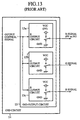
- Fig. 13 is a constitutional view of the OSD output circuit 15.
- the OSD output circuit 15 is composed of
- the selector 2 When a user uses the Braun tube 7, because the user does not generally adjust the Braun tube 7, the selector 2 is preset to select a composite video signal received by the video input terminal 1. Therefore, the composite video signal of the VTR or a composite video signal of a television program sent from the broadcasting station is selected by the selector 5 according to a user's selection and is input to the video processing circuit 6. In the circuit 6, the composite video signal is converted into a video signal, and a video image or a desired broadcasting image of the television program is displayed on the Braun tube 7 according to the video signal.
- horizontal synchronizing signals H sync and a vertical synchronizing signal V sync are demultiplexed from the composite video signal for each field in the video processing circuit 6, and the horizontal synchronizing signals H sync and the vertical synchronizing signal V sync are sent to the OSD circuit 14 of the microcomputer-for-television 9 in synchronization with the horizontal synchronizing signals H sync and the vertical synchronizing signal V sync multiplexed in the video signal.
- an OSD character such as a channel number "5" on the upper right side of the Braun tube 7 (refer to the Braun tube 7 shown in Fig. 12)
- the user inputs an instruction to a television set, and a display instruction of the OSD character is sent from the CPU 10 to the OSD circuit 14 and the OSD character output clock circuit 13.
- an OSD character output clock signal indicating a display period of the OSD character is generated and is sent to the OSD circuit 14.
- a dot pattern of the OSD character is read out from the internal ROM according to the display instruction and is output to the video processing circuit 6 in synchronization with the OSD character output clock signal, the horizontal synchronizing signals H sync and the vertical synchronizing signal V sync .
- the numbers of the horizontal scanning lines corresponding to the dot pattern of the OSD character are determined according to the specific information on the basis of the horizontal synchronizing signals H sync and the vertical synchronizing signal V sync sent from the video processing circuit 6, and the dot pattern of the OSD character is output to the video processing circuit 6 in the display period of the OSD character indicated by the OSD character output clock signal in synchronization with the horizontal synchronizing signals H sync and the vertical synchronizing signal V sync .
- the R, G and B signals indicating the dot pattern of the OSD character are mixed with the video signal. Thereafter, the OSD character is displayed with the desired broadcasting image or the video image on the Braun tube 7.
- Fig. 14 shows an output timing of a dot pattern of a channel number "5" (indicated by an arrow) corresponding to one horizontal scanning line indicated by one horizontal synchronizing signal.
- a G signal indicating a dot pattern (that is, a string of dots) of a channel number "5" representing the OSD character is only output from the G terminal to the video processing circuit 6, and a string of green dots is displayed on the upper right side of the image for each horizontal scanning line. Therefore, the channel number "5" indicated by green is displayed with the image.
- the selector 2 is set to select a composite video signal sent from the composite video signal outputting circuit 11, and the terminal output control circuit 12 is set under the control of the CPU 10 to make the selector 5 select the composite video signal sent from the selector 2. Thereafter, a composite video signal of a test pattern is produced in the composite video signal outputting circuit 11 and the resistors 16 and 17.
- the composite video signal indicating the test pattern is produced by inputting the main clock signal generated in the oscillating circuit 8 to the private circuit patterned in the composite video signal outputting circuit 11. Therefore, the composite video signal, in which signals are always multiplexed at fixed timings, can be obtained.
- the composite video signal are indicated by the pattern output level fixed to 5 V and the GND level (0 V).
- the pedestal level having a fixed electric potential is required for the composite video signal to indicate the black color, the horizontal synchronizing signals and the vertical synchronizing signal, the pedestal level of a fixed electric potential is added to the composite video signal by using the resistors 16 and 17 of resistances R1 and R2.
- the port of the microcomputer-for-television 9 is set to a high impedance condition to obtain an intermediate electric potential Vp from the pattern output level fixed to 5 V. Therefore, the pattern output level of the composite video signal set in the composite video signal output circuit 11 is changed to the pedestal level equal to the intermediate level Vp.
- Vp ⁇ R2/(R1 + R2) ⁇ * 5 (V)
- the pedestal level Vp is obtained from the fixed level 5 V, the pedestal level can be fixed.
- the composite video signal indicated by the pattern output level (5 V), the GND level (0 V) and the pedestal level (Vp) is sent to the video processing circuit 6 through the selectors 2 and 5 and is converted into a video signal in the video processing circuit 6.
- the test pattern indicated by the video signal is displayed on the Braun tube 7, in the same manner as the display of the broadcasting image. Therefore, a manufacturer can adjust the Braun tube 7 while viewing the test pattern.
- Fig. 15 is an explanatory view showing a cross-hatched pattern representing the test pattern and a waveform of a composite video signal of the cross-hatched pattern corresponding to one horizontal scanning line according to the NTSC.
- the composite video signal is indicated by the pattern output level fixed to 5 V, the GND level (0 V) and the pedestal level (Vp), and a cross-hatched pattern indicated by black and white (or one brightest color) is shown on the Braun tube 7.
- the composite video signal of the test pattern of which display modes such as shape, position, size and color are predetermined, is produced, and the test pattern can be reliably displayed on the Braun tube 7.
- the pedestal level is added to the composite video signal indicated by the pattern output level fixed to 5 V and the GND level (0 V) by using the resistors 16 and 17 and controlling the port output level of the composite video signal in the microcomputer-for-television 9, the test pattern indicated by a color of the highest luminance degree and the black color can be displayed on the Braun tube 7.
- the composite video signal having three output levels can be output from the composite video signal output circuit 11 and the resistors 16 and 17, because it is required to set the pedestal level to the fixed level Vp, the pattern output level cannot be adjusted to an arbitrary level. That is, the pattern output level is fixed to 5 V. Therefore, there is another drawback that a color level (or the luminance) of the test pattern indicated by the pattern output level (5 V) cannot be adjusted.
- test pattern is predetermined in the patterned private circuit
- setting conditions for example, cross-hatched pattern or upper-right side
- the display modes for example, shape or position
- a main object of the present, invention is to provide a video signal producing apparatus which has a small size and is obtained at a low cost. Also, the main object of the present invention is to provide a video signal producing method performed in the apparatus.
- a first subordinate object of the present invention is to provide video signal producing apparatus and method in which the luminance of a test pattern is minutely adjusted.
- a second subordinate object of the present invention is to provide video signal producing apparatus and method in which the setting conditions of the display modes of the test pattern are easily changed.
- a video signal producing apparatus comprising:
- a manufacturer or a user desires to adjust a display apparatus, it is required to send a composite video signal of a test pattern to the display apparatus and to display the test pattern on an image plane of the display apparatus as a test according to the composite video signal.
- a plurality of horizontal synchronizing signals and a vertical synchronizing signal matching with a video signal broadcasting standard to which the display apparatus is adapted are generated by the synchronizing signal generating means for each field.
- a display mode for example, shape, position, size, color or luminance degree
- the setting means so that the display mode of the test pattern composed of characters of the same type is set.
- a composite video signal of the test pattern satisfying the display mode is produced according to the horizontal synchronizing signals and the vertical synchronizing signal by the video signal producing means.
- the video signal producing apparatus can be produced in a small size. Also, because the video signal producing apparatus is produced in a small size, the cost of producing the video signal producing apparatus can be suppressed.
- the display mode of the characters set by the setting means be a display shape of the characters, a display position of each character, a display size of the characters, a display color of each character or the luminance of each character.
- a display shape for example, cross-hatched pattern obtained by combining a plurality of squared loops
- a position for example, upper-right side
- a size for example, a color (for example, red) and/or a luminance degree of the test pattern composed of the characters
- a color brightness of the test pattern can be specified by setting the color and luminance.
- the luminance of the characters be set to a particular luminance degree by the setting means as a setting condition of the display mode of the characters
- the video signal producing means comprise an output circuit for selecting a particular electric potential value corresponding to the particular luminance degree of the characters from three or more electric potential values including an electric potential value corresponding to black and an electric potential value corresponding to white and setting the electric potential of a pattern signal corresponding to the characters in the composite video signal to the particular electric potential value.
- the brightness of the test pattern displayed on the display apparatus can be selected from one or more intermediate brightness degrees other than brightness degrees corresponding to white and black. Accordingly, the brightness (or the luminance) of the test pattern displayed can be minutely adjusted.
- the video signal producing apparatus further comprises:
- one video signal broadcasting standard adapted in the video signal producing apparatus is renewed to a new video signal broadcasting standard such as NTSC, PAL system, Sequential Colors A Memoire (SECAM) or the like. Therefore, even though the display apparatus adapted to one video signal broadcasting standard is changed to a new display apparatus adapted to the new video signal broadcasting standard, the video signal broadcasting standard can be easily renewed to the new video signal broadcasting standard matching with the new display apparatus.
- NTSC NTSC
- PAL system PAL system
- SECAM Sequential Colors A Memoire
- the video signal producing apparatus further comprises:
- the predetermined setting condition of the display mode can be changed to a new setting condition (for example, upper-left side). Accordingly, setting conditions of display modes (for example, shape, position, size, color or luminance) for the test pattern can be easily changed.
- a video signal producing method comprising the steps of:
- the video signal producing method is useful for the video signal producing apparatus manufactured in a small size and at a low cost.
- step of setting the display mode of the characters include the step of:
- a color brightness of the test pattern can be specified by setting the color and luminance.
- step of setting the display mode of the characters include:
- the brightness (or the luminance) of the test pattern displayed can be minutely adjusted.
- step of generating the horizontal synchronizing signals and the vertical synchronizing signal matching with the video signal broadcasting standard includes the steps of:
- the video signal broadcasting standard can be easily renewed to the new video signal broadcasting standard matching with the new display apparatus.
- step of setting the display mode of the characters include the steps of:
- setting conditions of display modes for example, shape, position, size, color or luminance
- test pattern be obtained by combining the characters having the same shape set by the setting means.
- step of setting the display mode of the characters include the steps of:
- the test pattern is obtained by combining the characters having the same shape, even though a shape of the test pattern is complicated, the test pattern can be easily obtained by combining the characters having the same simple shape. Therefore, a small-sized video signal producing apparatus can be obtained at a low cost.
- Fig. 1 is a constitutional view of a video signal producing apparatus according to a first embodiment of the present invention.
- a video signal producing apparatus comprises:
- the OSD denotes a display method in which a channel number image, an image of a volume indication and/or a blue-back image for the whole image plane is displayed with a video image on a Braun tube.
- the microcomputer-for-television 29 comprises
- the OSD circuit 38 comprises
- Fig. 2 is a constitutional view showing the OSD output circuit 41.
- the OSD output circuit 41 comprises
- the lowest output level is used to specify horizontal synchronizing signals and one vertical synchronizing signal for each field
- the second lowest output level denoting the pedestal level corresponds to black (that is, the lowest luminance degree)
- the highest output level corresponds to the brightest color level or white (that is, the highest luminance degree). Therefore, other five output levels denote color levels of the intermediate luminance.
- the selector 22 is preset to select a composite video signal received by the video input terminal 21, the switches 33 and 34 are set to connect the OSD circuit 38 with the video processing circuit 26, and the switches 35 and 36 are set to disconnect the OSD circuit 38 from the timer circuit 32. Therefore, the composite video signal of the VTR or a composite video signal of a television program sent from the broadcasting station is selected by the selector 25 according to a user's selection and is input to the video processing circuit 26. In the circuit 26, the composite video signal is converted into a video signal, and a video image or a desired broadcasting image of the television program is displayed on the Braun tube 27 according to the video signal.
- horizontal synchronizing signals H sync and a vertical synchronizing signal V sync are demultiplexed from the composite video signal for each field in the video processing circuit 26, and the horizontal synchronizing signals H sync and the vertical synchronizing signal V sync are sent to the OSD circuit 38 of the microcomputer-for-television 29 through the switches 33 and 34 in synchronization with the horizontal synchronizing signals H sync and the vertical synchronizing signal V sync multiplexed in the composite video signal.
- an OSD character for example, a channel number "5"
- the user inputs an instruction to a television set, and a display instruction of the OSD character is sent from the CPU 30 to the OSD circuit 38 and the OSD character output clock circuit 37.
- an OSD character output clock signal indicating a display period of the OSD character is generated and is sent to the OSD circuit 38.
- a dot pattern of the OSD character is read out from the internal memory 39 to the control circuit 40 according to the display instruction and is output from the R, G and B terminals to the video processing circuit 26 in synchronization with the OSD character output clock signal, the horizontal synchronizing signals H sync and the vertical synchronizing signal V sync .
- a display position of the OSD character, a display size of the OSD character and a display color of the OSD character are included in the display instruction
- the numbers of horizontal scanning lines corresponding to the OSD character are specified according to the display position and the display size in the control circuit 40
- the composite video signal of the OSD character to be applied on the horizontal scanning lines in the Braun tube 27 are determined as the R, G and B signals according to the display position, the display size and the display color
- an output timing of the R, G and B signals indicating the dot pattern of the OSD character is determined according to the horizontal synchronizing signals H sync and the vertical synchronizing signal V sync corresponding to the display position of the OSD character for each of fields in the display period indicated by the OSD character output clock signal
- the R, G and B signals are output according to the output timing to send the dot pattern of the OSD character to the video processing circuit 26.
- the dot pattern of the OSD character is mixed with the desired broadcasting image or the video image in the video processing circuit 26, and the dot pattern of the OSD character is displayed with the desired broadcasting image or the video image on the Braun tube 27.
- Fig. 4 shows an output timing of the R, G and B signals corresponding to one horizontal scanning line to which a dot pattern of a channel number representing the OSD character is applied.
- the change-over switch of the G output circuit 41b is only controlled (that is, an output level of 0 V is selected in the R and B output circuits 41a and 41c), and a G signal of an output level (about 2.1 V) output from the G terminal is applied on one horizontal scanning line corresponding to a central portion (indicated by an arrow) of a channel number "5". Therefore, a string of green dots having a low luminance is displayed as the central portion of the channel number "5" on the upper right side of the image plane. As a result, the channel number "5" representing the OSD character is displayed at the low luminance green.
- the OSD character can be displayed by selecting one of seven luminance degrees.
- the selector 22 is set to select the R signal sent from the microcomputer-for-television 29, and the microcomputer-for-television 9 is set to make the selector 25 select an output signal sent from the selector 22.
- a composite video signal of a test pattern is produced in the microcomputer-for-television 29, the composite video signal is sent from the OSD circuit 38 to the video processing circuit 26 through the R terminal and the selectors 22 and 25, the composite video signal is converted into a video signal in the video processing circuit 26, and the test pattern indicated by the video signal is displayed on the Braun tube 27. Therefore, a manufacturer or the user can adjust the Braun tube 7.
- Fig. 3 is a flow chart showing a method for producing a composite video signal of the test pattern according to the first embodiment of the present invention.
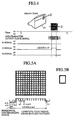
- Fig. 5A is an explanatory view showing a cross-hatched pattern representing the test pattern and a waveform of a composite video signal of the cross-hatched pattern corresponding to one horizontal scanning line according to the NTSC.
- the horizontal synchronizing signals and the vertical synchronizing signal produced in the timer circuit 32 are sent to the OSD circuit 38 through the switches 33 to 36, a composite video signal, in which all pattern signals corresponding to the test pattern are set to the pedestal level, is produced in the control circuit 40 under the control of the CPU 30, the composite video signal is output from the R terminal of the OSD output circuit 41, and a red image of the lowest luminance degree is initially displayed on the entire image plane of the Braun tube 27 according to the composite video signal (step ST4).
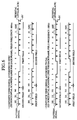
- Fig. 6 shows a composite video signal corresponding to an image of the lowest luminance degree according to the NTSC and a composite video signal corresponding to an image of the lowest luminance degree according to the PAL system.
- a composite video signal corresponding to an image of the lowest luminance degree is indicated by solid lines set to 0 V or the pedestal level, and pattern signals corresponding to an image of a test pattern described later is indicated by broken lines set to a pattern level higher than the pedestal level.
- the display modes of a test pattern are set in the control circuit 40 under the control of the CPU 30 to display the test pattern satisfying the display modes (steps ST5 to ST8).
- a particular type of character corresponding to a desired test pattern is selected from a plurality of types of characters stored in the memory 39 according to the specific information of the display instruction and is read out from the memory 39 to the control circuit 40 (step ST5).
- a particular type of character having a squared-loop shape is selected, and a cross-hatched pattern shown in Fig. 5A can be obtained as a shape of the test pattern by combining the particular type of characters.
- a display size of the characters (step ST6), a display color (for example, red, green or blue) of each character (step ST7), display positions (for example, upper-right side) of the characters in the horizontal and vertical directions (step ST8) and a luminance degree (that is, a level of the pattern signal) of each character (step S8) are set in the control circuit 40 according to the specific information of the display instruction sent from the CPU 30.
- a composite video signal satisfying the display modes of the test pattern is produced in the control circuit 40 on the basis of the horizontal synchronizing signals H sync and the vertical synchronizing signal V sync sent from the timer circuit 32 (step ST9).
- Fig. 7 is an explanatory view showing the relationship between the synchronizing signals produced in the timer circuit 32 and the composite video signal prepared in the control circuit 40.
- a series of horizontal synchronizing signals H sync and vertical synchronizing signal V sync indicated by the lowest level (0 V) and the pedestal level (black) is prepared from the horizontal synchronizing signals and the vertical synchronizing signal produced in the timer circuit 32, and pattern signals indicating the test pattern is multiplexed with the series of horizontal synchronizing signals H sync and vertical synchronizing signal V sync .
- a level of the composite video signal is selected from eight output levels in each of the R, G and B output circuits of the OSD output circuit 41, a level of the pattern signal is selected from six color levels other than levels corresponding to the black and 0 V. Therefore, a luminance degree of the test pattern is selected from six luminance degrees.
- the composite video signal is output from the R terminal of the OSD output circuit 41 to the video processing circuit 26 through the selectors 22 and 25 according to the OSD character output clock signal produced in the OSD character output clock circuit 37 (step ST10). Therefore, the test pattern can be easily prepared by combining the same type of characters set to the setting conditions of the display modes, and the composite video signal shown in Fig. 6 is, for example, produced and sent to the video processing circuit 26.
- the composite video signal of the test pattern is output only from the R terminal to display a red-colored image of the test pattern on the Braun tube 27.
- the composite video signal of the test pattern be output from the G or B terminal.
- the composite video signal of the test pattern be output from a plurality of terminals selected from the R, G and B terminals.
- the test pattern is prepared by combining the same type of characters.
- an arbitrary OSD character such as a numeral be included in the test pattern (refer to Fig. 8).
- a composite video signal is produced from a character pattern obtained by combining characters of the test pattern and the OSD character, and display modes (shape, position, size, color and luminance) of the OSD character are set in the control circuit 40 under the control of the CPU 30 in the same manner as those of the test pattern.
- one type of character corresponding to one test pattern is selected from various types of characters stored in the in memory 39, display modes of the type of character are set in the control circuit 40 under the control of the CPU 30, and a composite video signal of the test pattern, which is composed of the same type of characters satisfying the display modes, is produced according to the horizontal synchronizing signals and the vertical synchronizing signal which are produced in the timer circuit 32 and match with the video signal broadcasting standards such as NTSC or PAL. Therefore, because the composite video signal can be manufactured without using any private circuit, a small-sized video signal producing apparatus can be provided. Also, because the small-sized video signal producing apparatus can be provided, the apparatus can be obtained at a low cost.
- an output level of the composite video signal corresponding to the test pattern can be selected from eight output levels in each of the R, G and B output circuits of the OSD output circuit 41, the luminance degree of the type of character can be selected from six luminance degrees other than the luminance degree corresponding to the black. Therefore, the luminance level of the test pattern can be easily adjusted.
- the test pattern is obtained by combining the characters having the same shape, even though the test pattern has a complicated shape such as a shape of the cross-hatched pattern, the test pattern can be obtained by combining characters having the same simple shape such as a squared-loop shape, Accordingly, it is not required to store the test pattern having the complicated shape, a size of the memory 39 can be made small, and the video signal producing apparatus can be manufactured in a small size and at a low cost.
- an output level of the composite video signal corresponding to an OSD character such as a channel number can be selected from eight output levels in each of the R, G and B output circuits of the OSD output circuit 41, the luminance degree of the OSD character can be selected from six luminance degrees. Therefore, the luminance level of the OSD character can be easily adjusted.
- Fig. 9 is a constitutional view of a video signal producing apparatus according to a second embodiment of the present invention.
- the microcomputer-for-television 29 of a voltage setting circuit shown in Fig. 9 further comprises
- the setting condition changing instruction is sent to the CPU 30. Therefore, when the microcomputer-for-television 29 is operated to display a test pattern or an OSD character at predetermined setting conditions (for example, "upper right") of the display modes (for example, position) on the Braun tube 27, a composite video signal of a test pattern or an OSD character satisfying the display modes set to the new setting conditions are produced in the control circuit 40 under the control of the CPU 30, and the test pattern or the OSD character is displayed on the Braun tube 27 at the new setting conditions of the display modes.
- predetermined setting conditions for example, "upper right
- the broadcasting standard renewing instruction is sent to the CPU 30, horizontal synchronizing signals and a vertical synchronizing signal matching with the group of new video signal broadcasting standards are produced in the timer circuit 32 for each field, and a composite video signal of a test pattern or an OSD character is produced according to the horizontal synchronizing signals and the vertical synchronizing signal matching with the group of new video signal broadcasting standards. Therefore, a video signal matching with the group of new video signal broadcasting standards is produced in the video processing circuit 26, and the test pattern or the OSD character is displayed on the Braun tube 27 without any trouble.
- the setting conditions of the display modes of the test pattern or the OSD character predetermined in the microcomputer-for-television 29 can be easily changed to the new setting conditions.
- the group of video signal broadcasting standards predetermined in the microcomputer-for-television 29 can be easily renewed to the new video signal broadcasting standards such as NTSC, PAL, Sequential Colors A Memoire (SECAM) or the like.
- new video signal broadcasting standards such as NTSC, PAL, Sequential Colors A Memoire (SECAM) or the like.
Landscapes
- Engineering & Computer Science (AREA)
- Health & Medical Sciences (AREA)
- Biomedical Technology (AREA)
- General Health & Medical Sciences (AREA)
- Multimedia (AREA)
- Signal Processing (AREA)
- Testing, Inspecting, Measuring Of Stereoscopic Televisions And Televisions (AREA)
- Controls And Circuits For Display Device (AREA)
- Processing Of Color Television Signals (AREA)
Applications Claiming Priority (2)
| Application Number | Priority Date | Filing Date | Title |
|---|---|---|---|
| JP28022999 | 1999-09-30 | ||
| JP28022999A JP2001103518A (ja) | 1999-09-30 | 1999-09-30 | ビデオ信号作成装置及びビデオ信号作成方法 |
Publications (2)
| Publication Number | Publication Date |
|---|---|
| EP1089574A2 true EP1089574A2 (de) | 2001-04-04 |
| EP1089574A3 EP1089574A3 (de) | 2004-01-28 |
Family
ID=17622117
Family Applications (1)
| Application Number | Title | Priority Date | Filing Date |
|---|---|---|---|
| EP00109975A Withdrawn EP1089574A3 (de) | 1999-09-30 | 2000-05-11 | Gerät und Verfahren zur Produktion eines Videosignals |
Country Status (3)
| Country | Link |
|---|---|
| US (1) | US6628324B1 (de) |
| EP (1) | EP1089574A3 (de) |
| JP (1) | JP2001103518A (de) |
Families Citing this family (7)
| Publication number | Priority date | Publication date | Assignee | Title |
|---|---|---|---|---|
| US6474159B1 (en) * | 2000-04-21 | 2002-11-05 | Intersense, Inc. | Motion-tracking |
| US7006130B2 (en) * | 2001-05-11 | 2006-02-28 | John H. Harshbarger, Jr. | Visual cue for display testing having one bit resolution |
| US7102613B1 (en) * | 2001-07-17 | 2006-09-05 | National Semiconductor Corporation | Low cost vertical visual indicator system for on screen displays |
| JP4438696B2 (ja) * | 2005-06-15 | 2010-03-24 | セイコーエプソン株式会社 | 画像表示装置及び方法 |
| JP4491552B2 (ja) * | 2005-06-22 | 2010-06-30 | テクトロニクス・インターナショナル・セールス・ゲーエムベーハー | ビデオ・テスト信号の選択方法 |
| US8358379B1 (en) * | 2009-07-31 | 2013-01-22 | Pixelworks, Inc. | Post processing displays with on-screen displays |
| JP7109272B2 (ja) * | 2018-06-18 | 2022-07-29 | ローム株式会社 | 半導体集積回路、ブリッジチップ、ディスプレイシステム、自動車 |
Family Cites Families (8)
| Publication number | Priority date | Publication date | Assignee | Title |
|---|---|---|---|---|
| US4513318A (en) * | 1982-09-30 | 1985-04-23 | Allied Corporation | Programmable video test pattern generator for display systems |
| EP0323677A1 (de) * | 1988-01-07 | 1989-07-12 | Koninklijke Philips Electronics N.V. | Bildwiedergabeanordnung mit einem Wellengenerator |
| JPH03226080A (ja) | 1990-01-30 | 1991-10-07 | Toshiba Corp | キャラクタジェネレータ回路 |
| KR960009815B1 (en) * | 1993-12-29 | 1996-07-24 | Daewoo Electronics Co Ltd | Character or title signal mixing circuit of video appliance |
| JP3226080B2 (ja) | 1994-10-17 | 2001-11-05 | 株式会社豊田自動織機 | リーチ式フォークリフトの駆動制御装置 |
| KR0138285B1 (ko) * | 1995-01-20 | 1998-05-15 | 김광호 | 버스 제어방식을 채용한 텔레비젼과 그 제어방법 |
| US6326996B1 (en) * | 1995-11-06 | 2001-12-04 | Gateway, Inc. | Display device having self contained diagnostic image generation capability |
| JPH10171441A (ja) | 1996-12-13 | 1998-06-26 | Sanyo Electric Co Ltd | 文字表示制御回路 |
-
1999
- 1999-09-30 JP JP28022999A patent/JP2001103518A/ja active Pending
-
2000
- 2000-04-11 US US09/546,522 patent/US6628324B1/en not_active Expired - Fee Related
- 2000-05-11 EP EP00109975A patent/EP1089574A3/de not_active Withdrawn
Also Published As
| Publication number | Publication date |
|---|---|
| JP2001103518A (ja) | 2001-04-13 |
| EP1089574A3 (de) | 2004-01-28 |
| US6628324B1 (en) | 2003-09-30 |
Similar Documents
| Publication | Publication Date | Title |
|---|---|---|
| US7734143B2 (en) | Image processing apparatus capable of adjusting image quality by using moving image samples | |
| EP0230787A2 (de) | Bild-im-Bild-Fernsehempfänger | |
| US6204884B1 (en) | Multisystem television which is usable as a monitor of a personal computer and a method thereof | |
| EP0229526A2 (de) | Bild-im-Bild-Fernsehempfänger | |
| US7215357B1 (en) | Line blanker system | |
| AU603377B2 (en) | Television receiver | |
| US5729300A (en) | Double-screen simultaneous viewing circuit of a wide-television | |
| JPH06311449A (ja) | テレビジョン受像機 | |
| JP3301803B2 (ja) | テレビジョン受信機 | |
| EP0462784A2 (de) | Gerät und Verfahren zur Bildverarbeitung | |
| JPH07184137A (ja) | テレビジョン受像装置 | |
| US6628324B1 (en) | Video signal producing apparatus and video signal producing method | |
| EP0881842B1 (de) | Anordnung zum Erzeugen eines Monitorausgangssignals bei HDTV | |
| US6621526B1 (en) | Colorimetry converting apparatus | |
| KR20000074940A (ko) | Tv의 외부기기 소스 인터페이싱 시스템 | |
| JP2998156B2 (ja) | テレビジョン受像機 | |
| US5894332A (en) | Scanning circuit structure of a television receiver | |
| US5523789A (en) | High definition television monitor for displaying video images reproduced from normal standard video signals | |
| US5223928A (en) | Television receiver | |
| JP2003323168A (ja) | プロジェクタ装置 | |
| JP2603673Y2 (ja) | テレビジョン受信機 | |
| JPH01273489A (ja) | 高品位テレビ受像機 | |
| JPH06141252A (ja) | モニタ装置 | |
| US7408584B2 (en) | Producing video signals using sensor and lenticular lens pattern | |
| KR100208002B1 (ko) | 영상 신호 발생 장치 |
Legal Events
| Date | Code | Title | Description |
|---|---|---|---|
| PUAI | Public reference made under article 153(3) epc to a published international application that has entered the european phase |
Free format text: ORIGINAL CODE: 0009012 |
|
| AK | Designated contracting states |
Kind code of ref document: A2 Designated state(s): AT BE CH CY DE DK ES FI FR GB GR IE IT LI LU MC NL PT SE |
|
| AX | Request for extension of the european patent |
Free format text: AL;LT;LV;MK;RO;SI |
|
| RAP1 | Party data changed (applicant data changed or rights of an application transferred) |
Owner name: MITSUBISHI ELECTRIC SEMICONDUCTOR APPLICATION ENGI Owner name: MITSUBISHI DENKI KABUSHIKI KAISHA |
|
| REG | Reference to a national code |
Ref country code: DE Ref legal event code: 8566 |
|
| PUAL | Search report despatched |
Free format text: ORIGINAL CODE: 0009013 |
|
| AK | Designated contracting states |
Kind code of ref document: A3 Designated state(s): AT BE CH CY DE DK ES FI FR GB GR IE IT LI LU MC NL PT SE |
|
| AX | Request for extension of the european patent |
Extension state: AL LT LV MK RO SI |
|
| 17P | Request for examination filed |
Effective date: 20040331 |
|
| AKX | Designation fees paid |
Designated state(s): DE FR NL |
|
| 17Q | First examination report despatched |
Effective date: 20041112 |
|
| STAA | Information on the status of an ep patent application or granted ep patent |
Free format text: STATUS: THE APPLICATION HAS BEEN WITHDRAWN |
|
| 18W | Application withdrawn |
Effective date: 20041228 |