EP1089590A2 - Commutation de chemins virtuels en mode de transfer asynchrone dans un systeme de communications par satellites - Google Patents
Commutation de chemins virtuels en mode de transfer asynchrone dans un systeme de communications par satellites Download PDFInfo
- Publication number
- EP1089590A2 EP1089590A2 EP00119438A EP00119438A EP1089590A2 EP 1089590 A2 EP1089590 A2 EP 1089590A2 EP 00119438 A EP00119438 A EP 00119438A EP 00119438 A EP00119438 A EP 00119438A EP 1089590 A2 EP1089590 A2 EP 1089590A2
- Authority
- EP
- European Patent Office
- Prior art keywords
- vpi
- multicast
- output port
- data cell
- virtual path
- Prior art date
- Legal status (The legal status is an assumption and is not a legal conclusion. Google has not performed a legal analysis and makes no representation as to the accuracy of the status listed.)
- Withdrawn
Links
- 238000012545 processing Methods 0.000 title claims abstract description 62
- 238000004891 communication Methods 0.000 title claims abstract description 42
- 238000012546 transfer Methods 0.000 title description 10
- 238000000034 method Methods 0.000 claims abstract description 96
- 230000005540 biological transmission Effects 0.000 claims description 27
- 230000008878 coupling Effects 0.000 claims 1
- 238000010168 coupling process Methods 0.000 claims 1
- 238000005859 coupling reaction Methods 0.000 claims 1
- 208000037820 vascular cognitive impairment Diseases 0.000 abstract 2
- 230000004048 modification Effects 0.000 description 8
- 238000012986 modification Methods 0.000 description 8
- 230000009471 action Effects 0.000 description 7
- 239000004744 fabric Substances 0.000 description 6
- 230000005055 memory storage Effects 0.000 description 5
- 230000006870 function Effects 0.000 description 3
- 230000008569 process Effects 0.000 description 3
- 238000013507 mapping Methods 0.000 description 2
- 230000006727 cell loss Effects 0.000 description 1
- 230000008859 change Effects 0.000 description 1
- 230000000694 effects Effects 0.000 description 1
- 238000005516 engineering process Methods 0.000 description 1
- 239000002245 particle Substances 0.000 description 1
- 238000005510 radiation hardening Methods 0.000 description 1
- 230000010076 replication Effects 0.000 description 1
- 230000004044 response Effects 0.000 description 1
Images


Classifications
-
- H—ELECTRICITY
- H04—ELECTRIC COMMUNICATION TECHNIQUE
- H04L—TRANSMISSION OF DIGITAL INFORMATION, e.g. TELEGRAPHIC COMMUNICATION
- H04L49/00—Packet switching elements
- H04L49/30—Peripheral units, e.g. input or output ports
- H04L49/3081—ATM peripheral units, e.g. policing, insertion or extraction
- H04L49/309—Header conversion, routing tables or routing tags
-
- H—ELECTRICITY
- H04—ELECTRIC COMMUNICATION TECHNIQUE
- H04B—TRANSMISSION
- H04B7/00—Radio transmission systems, i.e. using radiation field
- H04B7/14—Relay systems
- H04B7/15—Active relay systems
- H04B7/185—Space-based or airborne stations; Stations for satellite systems
- H04B7/18578—Satellite systems for providing broadband data service to individual earth stations
- H04B7/18582—Arrangements for data linking, i.e. for data framing, for error recovery, for multiple access
-
- H—ELECTRICITY
- H04—ELECTRIC COMMUNICATION TECHNIQUE
- H04L—TRANSMISSION OF DIGITAL INFORMATION, e.g. TELEGRAPHIC COMMUNICATION
- H04L49/00—Packet switching elements
- H04L49/20—Support for services
- H04L49/201—Multicast operation; Broadcast operation
- H04L49/203—ATM switching fabrics with multicast or broadcast capabilities
-
- H—ELECTRICITY
- H04—ELECTRIC COMMUNICATION TECHNIQUE
- H04Q—SELECTING
- H04Q11/00—Selecting arrangements for multiplex systems
- H04Q11/04—Selecting arrangements for multiplex systems for time-division multiplexing
- H04Q11/0428—Integrated services digital network, i.e. systems for transmission of different types of digitised signals, e.g. speech, data, telecentral, television signals
- H04Q11/0478—Provisions for broadband connections
-
- H—ELECTRICITY
- H04—ELECTRIC COMMUNICATION TECHNIQUE
- H04L—TRANSMISSION OF DIGITAL INFORMATION, e.g. TELEGRAPHIC COMMUNICATION
- H04L12/00—Data switching networks
- H04L12/54—Store-and-forward switching systems
- H04L12/56—Packet switching systems
- H04L12/5601—Transfer mode dependent, e.g. ATM
- H04L2012/5603—Access techniques
- H04L2012/5604—Medium of transmission, e.g. fibre, cable, radio
- H04L2012/5608—Satellite
-
- H—ELECTRICITY
- H04—ELECTRIC COMMUNICATION TECHNIQUE
- H04L—TRANSMISSION OF DIGITAL INFORMATION, e.g. TELEGRAPHIC COMMUNICATION
- H04L12/00—Data switching networks
- H04L12/54—Store-and-forward switching systems
- H04L12/56—Packet switching systems
- H04L12/5601—Transfer mode dependent, e.g. ATM
- H04L2012/5619—Network Node Interface, e.g. tandem connections, transit switching
- H04L2012/5624—Path aspects, e.g. path bundling
Definitions
- the present invention relates to satellite communications systems. More specifically, the invention relates to a method and apparatus for virtual path asynchronous transfer mode switching in a processing satellite communications system.
- ATM Asynchronous Transfer Mode
- ATM is a cell-based switching and multiplexing technology which may be used as a general-purpose, connection-oriented transfer technique for a wide range of services.
- the primary unit of transfer in ATM is a cell (also referred to as an "ATM cell").
- Each ATM cell is a specifically formatted data unit that is 53 bytes long and includes 48 information bytes (referred to below as the "payload") and 5 header bytes (called the "cell header").
- the primary function of the cell header is to carry the address of the cell.
- the header includes two individual fields known as the Virtual Path Identifier (VPI) and the Virtual Channel Identifier (VCI), which jointly serve as the "addressing field.”
- VPI Virtual Path Identifier
- VCI Virtual Channel Identifier
- the VPI and VCI fields are comprised of 12 address bits and 16 address bits, respectively, providing a total of 28 bits of address.
- the process of switching an ATM cell at an ATM switch element generally includes two steps: a routing step and a relabeling step.
- a routing step an output port of the switch is identified for each cell that arrives at an input port of the switch.
- large routing tables at each connecting point (i.e., node) along the virtual connection are generally used to map the VPI and VCI from the input ports to the output ports of the ATM switch.
- the routing step may be performed, for example, by first indexing a particular memory location (as determined by part or all of the addressing field) in one of the routing tables.
- the routing information stored at the indexed memory location generally holds a routing tag which indicates the next link for the current ATM cell. This routing tag may then be attached to the current ATM cell, to identify that cell by its next link.
- the second step in ATM switching is a relabeling step.
- the VPI and VCI only have "local significance.” In other words, the VPI and VCI are only significant for one particular link of the virtual connection. Therefore, in order for accurate switching to occur at the next link, the VPI and possibly the VCI must often be changed or relabeled to provide a new address, so that the new address may be understood at the next link.
- a VC link is defined as the unidirectional transport of ATM cells with the same VCI between a VC connecting point (i.e., a node) and either a VC endpoint (i.e., the origination or destination) or another VC connecting point.
- a VP describes the unidirectional transport of ATM cells belonging to a group of VCs that are associated with a common VPI. Each VP has a bandwidth associated with it limiting the number of VCs that may be multiplexed on a VP.
- a VP link provides unidirectional transfer of cells with the same VPI between a VP connecting point and either a VP endpoint or another VP connecting point.
- VCC Virtual Channel Connection
- VPC Virtual Path Connection
- VP switching where only the VPI is considered in the switching action, and the VCI is ignored.
- VPI alone is sufficient to determine, for example, an appropriate memory location in the routing tables.
- relabeling of the VPI is allowed, but the VCI must remain unchanged.
- VC switching where the combination of the VCI and VPI is significant in both the routing and relabeling steps.
- Satellite systems commonly transmit and receive communications signals to and from user terminals.
- Such satellite based communications systems may utilize one satellite or a constellation of several satellites to relay communications signals to and from the user terminals (fixed or mobile).
- Each satellite includes at least one antenna which defines the satellite's coverage region on the earth called its footprint.
- the satellite antenna(s) may divide the footprint into multiple beam spots, or the footprint may be a single beam spot.
- Each beam spot is assigned one or more frequency bands (subbands), in which communications signals travel between the satellite and each user terminal.
- the user terminals communicate along preassigned communications channels in the subband.
- the transmission of information along a preassigned communications channel to a satellite switch occurs on the uplink, and the transmission of information along a preassigned communications channel from a satellite switch occurs on the downlink.
- Uplink transmissions may be demodulated and decoded at the satellite to recover one or more ATM cells that were conveyed across the uplink transmission path (TP).
- the ATM cells are then switched onto the downlink TP serving the destination earth terminal to which the cell is directed.
- processing satellite systems may incorporate crosslinks which link one satellite to another. These crosslinks are analogous to inter-switch transmission paths in terrestrial ATM networks.
- a virtual connection is generally established through the network from origination to destination, where ATM cells are routed over the same set of TPs for the duration of a call.
- the virtual connections may be, for example, a Virtual Path Connection (VPC) or a Virtual Channel Connection (VCC) from origination to destination.
- VPC Virtual Path Connection
- VCC Virtual Channel Connection
- a second disadvantage associated with past ATM switching applied to processing satellite communications systems is that VC switching (which is typically the type of ATM switching that is applied) would require a substantial amount of control traffic between a terrestrial network control center (NCC) and the satellite for each VCC that is set up or torn down by the system.
- NCC terrestrial network control center
- the setting up and tearing down of VCCs occurs quite frequently in a large scale system such as a processing satellite system.
- the presence of frequent bursts of control traffic between the NCC and satellites greatly reduces the bandwidth capacity available in the uplinks and downlinks for transmission of substantive information.
- the existence of control traffic introduces additional failure modes that may result due to lost or redirected cells bearing control information.
- the hardware required to process this control traffic increases the overall size and cost of the communications satellites.
- a third disadvantage associated with standard ATM switching in a processing satellite communications systems is that the relabeling of the VPI and VCI typically required for VC switching generally constitutes additional processing in the cell switching process. Again, this results in additional hardware requirements which leads to an increase in the size and cost of the communications satellites.
- One or more the of the foregoing objects is met in whole or in part by a method for virtual path switching of an ATM cell on a processing communications satellite.
- the method establishes a set of virtual path identifiers (VPIs), where each VPI is associated with an output port on the satellite.
- the method also establishes a set of virtual channel identifiers (VCIs), and assigns one VPI and one VCI to an ATM cell.
- VPIs virtual path identifiers
- VCIs virtual channel identifiers
- an ATM cell is transmitted to, and then received at an input port of the satellite.
- the method may then examine the assigned VPI to determine the output port associated with that VPI, and then transfer the ATM cell to the appropriate output port based only on the value of the assigned VPI.
- the VPI may be divided into a control subfield and a routing subfield.
- the routing subfield may then be examined to determine a corresponding output port to which the ATM cell is transferred.
- the present invention provides multicast switching.
- the method may include providing at least one multicast routing table, and providing at least one multicast output port which leads to a multicast module contained on the satellite.
- the VPI assigned to the ATM cell is associated with one multicast output.
- the ATM cell is transferred to that multicast output and then to the multicast module to which the multicast output leads.
- the multicast module may then examine the assigned VCI to determine (in one implementation) a corresponding memory location in one of the multicast routing tables.
- the addressing information at that memory location is read to determine a group of VPIs that represents the multicast group ("multicast group of VPIs"), and the ATM cell is reproduced for every distinct multicast group VPI.
- the reproduced ATM cells are reassigned with a new VPI from the multicast group VPIs, and the reproduced cells are once again presented to an input port of the satellite. Thereafter, the reproduced cells are routed by the switch as though they are non-multicast cells.
- FIG. 1 illustrates a flow chart 100 of a method for virtual path switching of an ATM cell on a processing satellite without the use of routing tables (referred to below as “the present method”).
- all virtual connections i.e., all virtual channel connections (VCCs) and virtual path connections (VPCs) in the processing satellite communications system are preferably addressed such that each downlink or crosslink transmission path may be determined from the virtual path identifier (VPI) alone for all cells present in the uplink.
- VCI virtual path identifier
- the present method may be modified in a variety of ways, some of which may include examining the VCI to determine the downlink transmission path.
- FIG. 9 illustrates an ATM switch 950 on a processing satellite.
- the ATM switch 950 generally includes an input module 952, a switch fabric 970 and an output module 980.
- the input module 952 may further include several input ports 954 and an examining circuit 956.
- the output module 980 may include several output ports 982.
- each output port 982 is uniquely associated with a single VPI, and the examining circuit 956 may easily determine to which output to switch a cell based on the cell's VPI.
- an ATM cell is received at an input port of a cell switch on a processing satellite (step 110).
- the VPI of the current ATM cell is examined (step 112) by an examining circuit (described further below) to determine with which of the several output ports that VPI is uniquely associated (step 114).
- the cell is then transferred to that output port (step 116), from which the cell may then be sent to the next connecting point on a corresponding crosslink or to its destination on a corresponding downlink (step 118).
- preliminary steps 102-108 of the present method 100 Prior to the switching steps described above, several preliminary steps 102-108 of the present method 100 generally occur to prepare the processing satellite system for switching of ATM cells. These preliminary actions may include, for example, establishing a virtual connection on which to transfer an ATM cell from the cell's origination to its destination (step 102) and establishing a set of VPIs and VCIs (steps 104, 106). Further, the present method includes assigning a particular VPI and VCI to the ATM cell (step 108).
- the step of establishing a set of VPIs includes establishing within the set of VPIs a single VPI uniquely associated with each output port, where each output port generally corresponds to a single downlink transmission path.
- the virtual connection is established by a terrestrial control infrastructure such as a network control center ("NCC").
- NCC network control center
- the NCC is a control center that manages transmission of information in a satellite communications system.
- the NCC manages the operation and status of system resources.
- the NCC relays communications signals to and from the user terminals and to and from the processing satellites.
- a user terminal may send an access request to the NCC, informing the NCC that the user terminal desires a connection with another user in the system.
- the access request is conveyed to the NCC via one or more satellites.
- the NCC selects an available virtual connection.
- the NCC performs an ATM Connection Admission Control (CAC) procedure. If the access request is granted, the NCC may assign a currently unused VCI for the virtual connection between the original user terminal to the destination terminal.
- CAC ATM Connection Admission Control
- the NCC informs the user terminal of the particular virtual connection via which the user terminal is to communicate, and further informs all the ATM nodes that make up the particular VPC or VCC that has been established.
- the NCC assigns an appropriate VPI and VCI (referred to below as the assigned VPI and assigned VCI, respectively) to the ATM cells being transmitted by the user terminal (step 108).
- the VPI and VCI are respectively chosen from a set of VPI and VCIs established, for example, by the NCC (104, 106).
- the assigned VPI is uniquely associated with a specific transmission path and thus, the assigned VPI constitutes the routing tag for that ATM cell. This is explained further below.
- the VCI generally indicates the particular ATM device or user terminal to which the ATM cell is directed.
- the VPI and VCI generally only have "local significance" (i.e., they only have significance for a particular link within the virtual connection).
- the VPI and sometimes the VCI are often relabeled at an ATM switching device before the ATM cell is sent on its next link.
- the VPI and VCI remain unchanged as a cell transits each link of its virtual connection.
- An ATM switch on a processing satellite generally has several output ports to which ATM cells are transferred after they are routed by the switch fabric.
- each ATM cell is preferably sent to an output port based only on the VPI in the cell's addressing field.
- the present method may be refined in various ways such that the VCI may also be taken into account.
- the VPI of the current ATM cell is examined at the satellite (step 112).
- the examining function may be done by an examining circuit 956.
- the examining circuit 956 may include, for example, a header processor 960 and either a hardwired identifier logic unit or a CPU/software combination 958.
- the examining circuit 956 then translates the VPI to determine with which output port the examined VPI is associated (step 114).
- the header processor 960 After the VPI is examined and translated by the examining circuit 956, the header processor 960 outputs a routing signal 962 to the switch fabric 970 of the ATM switch 950, indicating to which output port 982 the current ATM cell should be directed.
- the switch fabric 970 which may generally couple ATM cells from an input port to an output port based on the VPI, then transfers the current ATM cell to the appropriate output port 982 based on the routing signal 262 from the header processor 960 (step 116). Once in the appropriate output port, the ATM cell is sent either on a crosslink to the next connecting point along the virtual circuit, or on the downlink directly to the destination user terminal (step 118).
- the VPI itself provides all information needed to transfer cells across a virtual circuit, including in situations where one or more of the transmission paths may be a crosslink.
- Figure 2 which shows a system comprised of three processing satellites 214, 216, 218 connected by crosslinks 208, 210.
- Figure 2 further shows a user terminal in Los Angeles 202 and another user terminal in London 204.
- 64 beams are provided by each of the three satellites for a total of 192 beams.
- the three satellites 214, 216, 218 may be located, for example, at 120W, 60W and 0 longitude, respectively.
- VPIs numbered 64 through 127 may be associated with the westerly satellite's beams 214, 128 through 191 may be associated with the central satellite's beams 216, and 192 through 255 may be associated with the easterly satellite's beams 218.
- the beam serving the Los Angeles terminal may be beam number 123 and the beam serving London terminal may be beam number 234.
- the VCI selected is a 16 bit number unused by any other virtual connection terminating in the London beam (numbered 234).
- the VCI is assumed to be "X".
- the Los Angeles user terminal 202 addresses all cells directed to the London user terminal 204 with the specific VPI/VCI labeled 234/X, and launches those cells in its uplink 200.
- the westerly satellite 214 all cells with VPIs in the range 128 through 255 are switched to the output port serving the next crosslink 208. This switching is effected without a lookup table or routing table. Rather, in accordance with the present method, the switching is based solely on the appropriate bits in the VPI field.
- the cell After transiting the next crosslink 208, the cell arrives at the central satellite 216. Based on the present method, at the central satellite 216, all cells with VPIs in the range 192 to 255 are switched to the output port serving crosslink 210, again without any lookup or routing tables. After transiting crosslink 210, the cell arrives at the easterly satellite 218 where the cell is routed into the downlink 212 serving the London beam, beam number 234. At the easterly satellite 218 all cells with VPIs in the range 192 though 255 are routed to the corresponding downlink beam, where each of these downlink beams emanates from the easterly satellite 218. The example cell is routed from the crosslink to the output port serving beam 234 (London beam). The destination terminal 204 in the present example examines each cell present in the downlink 212 for beam 234 and reads only those cells with VCI equal to X.
- the present method is improved to provide for multicast switching.
- Multicast switching provides the capability for a single ATM cell in the uplink to be routed to more than one destination in multiple downlink transmission paths (referred to as a multicast cell).
- the set of user terminals that are intended recipients of a multicast cell is referred to as a "multicast group.”
- multicast switching may be implemented at the satellite switching element 300 by using one or more multicast modules 302 connected between an input module 301 and output module 307 of the satellite switch 300.
- the satellite switch 300 includes several input ports 304 in an input module 301, several output ports 306 in an output module 307, and a switch fabric 305. Although the case of one multicast module will be examined below, more than one multicast module may be used.
- a multicast module 302 may be implemented as a duplicating circuit which provides for the replication of the ATM cell seeking multicast switching (i.e., the "multicast cell"), and for relabeling of the addressing fields of the replicated multicast cells.
- each multicast module 302 is connected between the input module 301 and the output module 307 of the satellite switch 300.
- each multicast module 302 is connected to one or more multicast routing tables 308.
- the established set of VPIs includes one or more multicast VPIs.
- a multicast VPI is a particular type of VPI which is uniquely associated with an output port leading to a multicast module (rather than leading to a downlink transmission path, as described with respect to the present method).
- every multicast cell in a system which provides for multicast switching is assigned a specific type of VPI, a "multicast VPI" (see step 108 of Figure 1).
- a multicast VPI is a specific type of VPI that is, in general, uniquely associated with a multicast output port (i.e., an output port leading to a multicast module).
- the VCI which is assigned to the multicast cell indicates the multicast group to which the multicast cell belongs.
- the multicast VPI in the addressing field of that multicast cell is examined and translated by a header processor (as explained above with respect to Figure 1 and the present method). Then, the multicast cell is routed to a specific output port 306 which corresponds to the multicast VPI examined and translated by the header processor.
- each specific output port 306 which corresponds to a multicast VPI directs multicast cells to a particular multicast module 302.
- one or more multicast routing tables 308 may be provided for use in determining to which multicast group the multicast cell belongs.
- the multicast module 302 upon receiving the multicast cell, the multicast module 302 reads the information stored at a particular memory storage location within one of the multicast routing tables 308. This memory storage location is generally determined by part or all of the VCI from the multicast ATM cell. The information stored at this memory storage location will typically be a set of VPIs which identifies the members of the multicast group (i.e., the multicast group VPIs).
- a new VCI must be known to the multicast module. Accordingly, when a new multicast group is created, all or part of the addressing field (i.e., the VPI only or the VPI and a new VCI) needed to service such uplink multicast cells are entered into the multicast routing tables.
- the multicast module 302 duplicates the current multicast cell to typically create at least as many reproduced ATM cells as there are distinct VPIs or downlink transmission paths leading to the members of the multicast group.
- the multicast module relabels each individual reproduced ATM cell with a new VPI (referred to below as a reassigned VPI) which, as in the present method discussed above, constitutes the routing tag for the individual reproduced ATM cells.
- each reproduced ATM cell is created by the multicast module 302 and then properly relabeled, the cells are output from the multicast module back to an input port of the ATM switch element which is generally dedicated to the multicast module. Subsequently, each reproduced ATM cell is presented to an input port of the ATM switch element, and then each reproduced cell is switched to the output port uniquely associated with its reassigned VPI, according to the present method illustrated in Figure 1 and discussed above in detail.
- the output port uniquely associated with the reassigned VPI is referred to as the reproduced cell's "new output port.”
- a common VCI is used for each reproduced ATM cell so that the reproduced ATM cells differ only in their reassigned VPIs as they reenter the input ports of the ATM switch element. Further, since this common VCI may be the same one as is used in the uplink, no relabeling of the VCI is required.
- the multicast module may also relabel the VCI of one or more of the reproduced ATM cells.
- the ATM switch (as used in the present invention modified for multicast switching) accomplishes the switching action based only on the VPI (i.e., it relies only on VP switching). Thus, relabeling of the VCI has no effect on the multicast switching function according to the present invention.
- FIG. 4 illustrates a flow chart 400 of the present method for virtual path switching of ATM cell, where the method is modified to provide for multicast switching (referred to below as the "multicast switching method").
- the multicast switching method includes several preliminary steps 402-410 to prepare the processing satellite system for multicast switching of ATM cells.
- the preliminary steps include, for example, establishing a virtual connection 402, one or more multicast routing tables 404, a set of VPIs including at least one multicast VPI 408, and a set of VCIs 408.
- a VPI and a VCI are preferably assigned to the user terminal desiring to transmit multicast ATM cells 410. Where the ATM cell is a multicast cell, the VPI that is assigned will be a multicast VPI (as defined above). Similar to the present method, these preliminary steps are generally accomplished by the NCC.
- an ATM cell may be received at an input port of the uplink receiver on the satellite 412. It is noted that for purposes of this discussion regarding the multicast switching method, it is assumed that the ATM cell is a multicast cell. Therefore, the VPI is a multicast VPI and the associated output port is a multicast output port.
- the multicast VPI is examined 414 to determine with which of the output ports that multicast VPI is uniquely associated 416.
- the multicast cell is then transferred to the multicast output port uniquely associated with the multicast VPI 418.
- the multicast cell is received by the particular multicast module connected to the multicast output port uniquely associated with the multicast VPI 420.
- the VCI is then examined to determine, for example, a memory storage location within the multicast routing tables corresponding to that VCI 422, and the addressing information at that memory location is read to ascertain the members of the multicast group corresponding to the multicast cell 424.
- the multicast cell is duplicated to create at least as many reproduced ATM cells as there are distinct downlink transmission paths leading to the members of the multicast group 426.
- the reproduced ATM cells are relabeled with new VPIs (referred to as reassigned VPIs), such that the reassigned VPIs are determined based on the distinct downlink transmission paths leading to the members of the multicast group 428.
- the newly relabeled cells are then received at an input port of the ATM switching element 430, the reassigned VPIs are examined to determine with which output port each reassigned VPI is uniquely associated 432, and the newly relabeled cells are respectively transferred to the output port with which the reassigned VPIs are uniquely associated 434.
- the present invention may be refined to provide for an external virtual path connection.
- an ATM based processing satellite system forms part of an external ATM network
- a virtual connection which transits the processing satellite system from this external ATM network (referred to below as an "external" virtual connection or an “externally managed” virtual connection) may be required.
- An external VPC that transits a satellite based ATM switch in a processing satellite system is generally under the control of an external agency which retains management of the VPIs and VCIs (referred to as external VPIs and external VCIs, respectively) used within the external VPC.
- external VPIs and external VCIs respectively
- the processing satellite system's NCC or other terrestrial control infrastructure
- the external VPIs must be distinct from the VPIs under the management of the NCC. This avoids having any user terminals receive unwanted ATM cells.
- the present invention may be refined to provide for an external virtual path connection by including one or more routing tables 502 on each processing satellite connected to the input module 504 of the ATM switch 500.
- the routing tables are referred to below as input routing tables 502.
- the input routing tables 502 contain information for mapping the external VPIs into the appropriate transmission path.
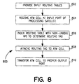
- Figure 6 illustrates a flow chart 600 of the present method for virtual path switching of ATM cells, where the method is modified to provide for an external virtual path connection.
- several preliminary actions 102-108 occur to prepare the satellite for switching of ATM cells. For example, a virtual connection from origination to destination is established at step 102.
- an external VPC is managed by an external controller independent of the processing satellite communication system.
- the method for virtual path ATM switching modified to allow for an external virtual path connection also includes establishing a set of VPIs and VCIs (104 and 106), and assigning a VPI and VCI to the current ATM cell 108, as described with respect to Figure 1.
- the assigned VPI and VCI are being managed by the external controller independent of the processing satellite communication system.
- the external VPC, the VPIs and the VCIs are established by the external controller, rather than the NCC.
- the external controller (rather than the NCC) assigns a VPI and VCI to the ATM cell.
- each memory location of the input routing tables contains a routing tag that represents a particular output port of the ATM switch.
- an ATM cell may be received at an input port of a processing satellite 604.
- the external VPI is then examined to determine which memory location of the input routing tables contains the proper routing tag 606.
- the contents of that memory location are read by the ATM switch to determine the routing tag 608, and then the ATM cell with the external VPI is transferred to the particular output port represented by the determined routing tag.
- the present method may be refined to provide for expanded addressing by including one or more routing tables 702 on the processing satellites connected to the input module 703 of the ATM switch 700 (referred to below as input routing tables).
- the present method may use as many as 2 16 , or 65,536 distinct addresses within a given downlink transmission path. In the event that more than 2 16 addresses are required to support a given downlink transmission path, the present method may be modified by assigning more than one VPI to that transmission path. However, where multiple VPIs are assigned to a single transmission path, a single VPI no longer uniquely identifies one output port 708, as in the present method. In other words, there is no longer a one-to-one correspondence between the VPI and the output ports 708.
- one or more routing tables 702 are connected to the input module 703 of the ATM switch 700 to aid the processing satellite in mapping the multiple VPIs for the virtual channels (VCs) supported by the downlink transmission path.
- the modification to account for expanded addressing is very similar to the modification for an external VPC.
- the modification to allow for expanded addressing includes the step of establishing a virtual connection from origination to destination 102 (although the virtual connection is not necessarily an external connection), establishing a set of VPIs and VCIs (104 and 106), and assigning a VPI and VCI to the current ATM cell, as described with respect to Figure 1.
- the virtual connection is not necessarily an external connection
- establishing a set of VPIs and VCIs 104 and 106
- assigning a VPI and VCI to the current ATM cell as described with respect to Figure 1.
- each memory location of the input routing tables contains a routing tag that identifies the next virtual channel link of the virtual connection.
- the ATM cell may be received at an input port of a processing satellite 804.
- the non-unique VPI then indexes an input routing table to determine the appropriate routing tag 806, and that routing tag is attached to the ATM cell 808. Then the ATM cell is transferred to an output port based on the assigned routing tag.
- the present method may be further refined to provide for special treatment of ATM cells on a VCC by VCC basis (referred to below as "VCC specialization").
- VCC specialization Frequently in a processing satellite, actions are required that necessitate special treatment of ATM cells. For example, application of differing levels of error control on the downlink of a transmission path to accommodate different levels of attenuation at a given earth terminal would require special treatment of ATM cells.
- Another example of a situation calling for VCC specialization would be where there are differing levels of queuing priority of ATM cells at an the output port of an ATM switch to accommodate different cell delay variation and/or cell loss priority.
- the present method may be modified to facilitate VCC specialization by setting aside a portion of the VPI to identify how a particular ATM cell is to be specially treated as it is being switched by the ATM switch fabric (referred to below as the "control subfield"). For example, one bit of the VPI may be reserved to indicate high or low priority in queuing. Another bit may be reserved for indicating the level of error control on the downlink.
- VCC specialization requires no change to the present method because the routing tag for the ATM cell may still be identified directly from the remaining bits (i.e., the routing subfield) of the VPI. It is important to note that since the control subfield is specified by the originating user terminal, VCC specialization does not require VCI routing tables (i.e., routing tables that are indexed by the VCI of an ATM cell).
- the present invention thus provides an efficient, low cost method of virtual path ATM switching in a processing satellite communications system. While particular elements, embodiments and applications of the present invention have been shown and described, it is understood that the invention is not limited thereto since modifications may be made by those skilled in the art, particularly in light of the foregoing teaching.
Landscapes
- Engineering & Computer Science (AREA)
- Computer Networks & Wireless Communication (AREA)
- Signal Processing (AREA)
- Physics & Mathematics (AREA)
- Astronomy & Astrophysics (AREA)
- Aviation & Aerospace Engineering (AREA)
- General Physics & Mathematics (AREA)
- Data Exchanges In Wide-Area Networks (AREA)
- Radio Relay Systems (AREA)
- Use Of Switch Circuits For Exchanges And Methods Of Control Of Multiplex Exchanges (AREA)
Applications Claiming Priority (2)
| Application Number | Priority Date | Filing Date | Title |
|---|---|---|---|
| US09/408,808 US7164683B1 (en) | 1999-09-29 | 1999-09-29 | Virtual path asynchronous transfer mode switching in a processing satellite communications system |
| US408808 | 1999-09-29 |
Publications (1)
| Publication Number | Publication Date |
|---|---|
| EP1089590A2 true EP1089590A2 (fr) | 2001-04-04 |
Family
ID=23617852
Family Applications (1)
| Application Number | Title | Priority Date | Filing Date |
|---|---|---|---|
| EP00119438A Withdrawn EP1089590A2 (fr) | 1999-09-29 | 2000-09-14 | Commutation de chemins virtuels en mode de transfer asynchrone dans un systeme de communications par satellites |
Country Status (4)
| Country | Link |
|---|---|
| US (1) | US7164683B1 (fr) |
| EP (1) | EP1089590A2 (fr) |
| JP (1) | JP2001148704A (fr) |
| CA (1) | CA2317792C (fr) |
Cited By (1)
| Publication number | Priority date | Publication date | Assignee | Title |
|---|---|---|---|---|
| EP1425863B2 (fr) † | 2001-09-12 | 2013-02-13 | The Boeing Company | Procede et appareil de detection de voie entre une plate-forme mobile et un segment terrestre |
Families Citing this family (3)
| Publication number | Priority date | Publication date | Assignee | Title |
|---|---|---|---|---|
| US8144690B2 (en) * | 2000-06-08 | 2012-03-27 | Thomson Licensing S.A. | ATM multicasting for delivering information over a network |
| US20040027155A1 (en) * | 2002-08-08 | 2004-02-12 | Schlansker Michael S. | System and method for self configuration of reconfigurable systems |
| US7366166B2 (en) * | 2003-04-25 | 2008-04-29 | Alcatel Usa Sourcing, L.P. | Data switching using soft configuration |
Family Cites Families (17)
| Publication number | Priority date | Publication date | Assignee | Title |
|---|---|---|---|---|
| JPH05235991A (ja) | 1992-02-25 | 1993-09-10 | Fujitsu Ltd | Atm交換機における分配接続方式 |
| JP3064650B2 (ja) | 1992-03-27 | 2000-07-12 | 株式会社日立製作所 | 同報通信装置 |
| JPH0779230A (ja) | 1993-09-09 | 1995-03-20 | Toshiba Corp | Atmスイッチノード装置及び網立ち上げ方法 |
| CA2151180C (fr) * | 1994-09-14 | 2003-11-04 | Robert Brownhill | Methode et appareil pour la multidiffusion de cellules mta |
| US5528588A (en) * | 1994-09-14 | 1996-06-18 | Fore Systems, Inc. | Multicast shared memory |
| KR100192651B1 (ko) * | 1994-12-07 | 1999-06-15 | 가나이 쓰도무 | 제어셀에 의해 입력셀의 전송을 제어하는 atm교환망, atm교환기 및 atm교환망에 있어서의 신호처리방법 |
| US5812528A (en) * | 1995-11-17 | 1998-09-22 | Telecommunications Techniques Corporation | Measuring round trip time in ATM network virtual connections |
| US5940381A (en) * | 1996-03-14 | 1999-08-17 | Motorola, Inc. | Asynchronous transfer mode radio communications system with handoff and method of operation |
| GB2316572B (en) * | 1996-08-14 | 2000-12-20 | Fujitsu Ltd | Multicasting in switching apparatus |
| JP3003779B2 (ja) * | 1997-06-24 | 2000-01-31 | 日本電気株式会社 | 通信システム |
| US5903564A (en) * | 1997-08-28 | 1999-05-11 | Ascend Communications, Inc. | Efficient multicast mapping in a network switch |
| US6707800B1 (en) * | 1998-10-01 | 2004-03-16 | Hughes Electronics Corporation | ATM network with central call processor |
| US6496508B1 (en) * | 1998-11-12 | 2002-12-17 | Nortel Networks Limited | Communication system architecture and method of establishing a communication connection therein |
| US6240075B1 (en) * | 1999-01-25 | 2001-05-29 | Trw Inc. | Satellite communication routing arbitration techniques |
| US6400925B1 (en) * | 1999-02-25 | 2002-06-04 | Trw Inc. | Packet switch control with layered software |
| US6295283B1 (en) * | 1999-05-11 | 2001-09-25 | Trw Inc. | Method for providing connectionless data services over a connection-oriented satellite network by associating IP subnets with downlink beam identifiers |
| US6366776B1 (en) * | 1999-09-29 | 2002-04-02 | Trw Inc. | End-to-end transmission techniques for a processing satellite system |
-
1999
- 1999-09-29 US US09/408,808 patent/US7164683B1/en not_active Expired - Fee Related
-
2000
- 2000-09-06 CA CA002317792A patent/CA2317792C/fr not_active Expired - Fee Related
- 2000-09-14 EP EP00119438A patent/EP1089590A2/fr not_active Withdrawn
- 2000-09-27 JP JP2000293554A patent/JP2001148704A/ja not_active Ceased
Cited By (1)
| Publication number | Priority date | Publication date | Assignee | Title |
|---|---|---|---|---|
| EP1425863B2 (fr) † | 2001-09-12 | 2013-02-13 | The Boeing Company | Procede et appareil de detection de voie entre une plate-forme mobile et un segment terrestre |
Also Published As
| Publication number | Publication date |
|---|---|
| US7164683B1 (en) | 2007-01-16 |
| JP2001148704A (ja) | 2001-05-29 |
| CA2317792C (fr) | 2005-11-15 |
| CA2317792A1 (fr) | 2001-03-29 |
Similar Documents
| Publication | Publication Date | Title |
|---|---|---|
| US5991297A (en) | Independently sizable memory pages for a plurality of connection ID types in a network switch | |
| US5787077A (en) | Dynamic connection mapping in wireless ATM systems | |
| US5907542A (en) | Dynamic assignment of signalling virtual channels for wireless ATM systems | |
| US5329527A (en) | Inter-local area network connecting system | |
| US5359603A (en) | Mobile radio systems | |
| US6295283B1 (en) | Method for providing connectionless data services over a connection-oriented satellite network by associating IP subnets with downlink beam identifiers | |
| US5777994A (en) | ATM switch and intermediate system | |
| US6285674B1 (en) | Hybrid distributed broadcast and unknown server for emulated local area networks | |
| GB2254529A (en) | Connectionless switching for an atm or dqdb switch | |
| US6707800B1 (en) | ATM network with central call processor | |
| US7164683B1 (en) | Virtual path asynchronous transfer mode switching in a processing satellite communications system | |
| US6625131B1 (en) | Satellite communication multicast processing techniques using multicast replication and outbound processing | |
| JP3373281B2 (ja) | ローカルネットワーク | |
| US6243363B1 (en) | Process of switching to a server of cells sent by a module linked to a local access network for mobile (stations), as well as such a network for implementation of said process | |
| US5654965A (en) | ATM communication network system with common system information storage | |
| KR19990087607A (ko) | Atm 네트워크를 통한 atm 셀의 전송 방법 | |
| US6301251B1 (en) | ATM communications system, UBR-ABR gateway, and method | |
| Priscoli | Interworking of a satellite system for mobile multimedia applications with the terrestrial networks | |
| JP3494264B2 (ja) | 衛星回線接続インタフェース装置 | |
| US6690643B1 (en) | Method of rerouting connection in multipoint connection | |
| KR100260898B1 (ko) | 엘.이.씨 초기화 기능 검증 시스템 | |
| KR0164123B1 (ko) | 에이티엠 교환시스템에서 연결식별자의 할당 및 해제 방법 | |
| KR20020008864A (ko) | 유토피아 인터페이스를 구비하는 에이티엠 통신시스템의셀 복사 장치 및 방법 | |
| KR20000054939A (ko) | 에이티엠 교환 시스템에서 이중 큐를 이용한 채널 할당 방법 | |
| KR980013086A (ko) | Atm 교환기의 신호 채널 구분 방법 |
Legal Events
| Date | Code | Title | Description |
|---|---|---|---|
| PUAI | Public reference made under article 153(3) epc to a published international application that has entered the european phase |
Free format text: ORIGINAL CODE: 0009012 |
|
| AK | Designated contracting states |
Kind code of ref document: A2 Designated state(s): AT BE CH CY DE DK ES FI FR GB GR IE IT LI LU MC NL PT SE |
|
| AX | Request for extension of the european patent |
Free format text: AL;LT;LV;MK;RO;SI |
|
| RIN1 | Information on inventor provided before grant (corrected) |
Inventor name: MANN, MICHAEL W. Inventor name: WRIGHT, DAVID A. Inventor name: WILLIAMS, RHON L. Inventor name: FALK, AARON D. |
|
| RAP1 | Party data changed (applicant data changed or rights of an application transferred) |
Owner name: NORTHROP GRUMMAN CORPORATION |
|
| RAP1 | Party data changed (applicant data changed or rights of an application transferred) |
Owner name: NORTHROP GRUMMAN CORPORATION |
|
| STAA | Information on the status of an ep patent application or granted ep patent |
Free format text: STATUS: THE APPLICATION IS DEEMED TO BE WITHDRAWN |
|
| 18D | Application deemed to be withdrawn |
Effective date: 20061003 |