EP1089604A1 - Echangeur de chaleur - Google Patents
Echangeur de chaleur Download PDFInfo
- Publication number
- EP1089604A1 EP1089604A1 EP00890262A EP00890262A EP1089604A1 EP 1089604 A1 EP1089604 A1 EP 1089604A1 EP 00890262 A EP00890262 A EP 00890262A EP 00890262 A EP00890262 A EP 00890262A EP 1089604 A1 EP1089604 A1 EP 1089604A1
- Authority
- EP
- European Patent Office
- Prior art keywords
- cold plate
- heat transfer
- header
- headers
- inlet
- Prior art date
- Legal status (The legal status is an assumption and is not a legal conclusion. Google has not performed a legal analysis and makes no representation as to the accuracy of the status listed.)
- Withdrawn
Links
Images



Classifications
-
- H—ELECTRICITY
- H10—SEMICONDUCTOR DEVICES; ELECTRIC SOLID-STATE DEVICES NOT OTHERWISE PROVIDED FOR
- H10W—GENERIC PACKAGES, INTERCONNECTIONS, CONNECTORS OR OTHER CONSTRUCTIONAL DETAILS OF DEVICES COVERED BY CLASS H10
- H10W40/00—Arrangements for thermal protection or thermal control
- H10W40/40—Arrangements for thermal protection or thermal control involving heat exchange by flowing fluids
- H10W40/47—Arrangements for thermal protection or thermal control involving heat exchange by flowing fluids by flowing liquids, e.g. forced water cooling
Definitions
- This invention relates to heat transfer cold plates for removing heat from electrical components and the like.
- the Iversen Patent No. 5,111,280 shows a cooling arrangement for semiconductor devices consisting of a plurality of plates on which the semiconductor devices are mounted, each plate having flow paths for cooling fluid extending between opposite ends of the plate and having terminals for one of three legs of a three-phase electrical system.
- Coolant supply and discharge manifolds made of electrically insulating material, such as ceramic or plastic, are affixed to the ends of the plates to circulate cooling fluid through the passages in the plates and to the spaces between the plates, using dielectric coolants such as fluorocarbons to assure electrical insulation.
- dielectric coolants such as fluorocarbons
- the Iverson et al. Patent No. 4,989,070 discloses a modular heat sink structure which includes a metal heat sink having semiconductor devices supported through insulating joints from adjacent surfaces of the heat sink and a coolant flow path extending beneath the insulated supports for the semiconductor devices from an inlet opening at one end of the plate to an outlet opening at the same end of the plate.
- Patent to Wolgemoth et al. No. 4,453,911 discloses a cold plate arrangement in which a cold plate made of plastic material has a coolant flow path extending from one end to the opposite end which directs coolant along the surfaces of power electronic components mounted on one side of the cold plate.
- a heat exchanger such as a hot water radiator for an automobile consists of a plurality of metal tubes having metal plates mounted between tanks made of rust proof synthetic resin.
- Another object to the invention is to provide a heat transfer cold plate arrangement having a simple and convenient construction.
- a heat transfer cold plate arrangement including a cold plate which is electrically isolated from its surroundings by nonmetallic electrically insulating headers disposed at opposite ends of the cold plate to direct coolant to flow in two directions through the cold plate from an inlet in one header to a return header and back to an outlet in the first header and in which the assembly is supported by one or more mounts attached to the insulating headers.
- the cold plate arrangement includes a metal plate having an array of parallel internal channels extending between opposite end surfaces and nonmetallic headers made of electrically insulating composite material attached to the opposite ends of the metal plate, one of the headers providing inlet and outlet fluid flow paths and the other header providing flow communication between the cold plate channels supplied by the inlet flow path and the channels connected to the outlet flow path.
- the headers may be sealingly attached to the ends of the metal plate by adhesive or by snap-in connections with compressed gasketing. Heat-generating components to be cooled are mounted on the metal plate, for example, by threaded holes in the surfaces of the plate. To provide electrical isolation from adjacent components, the assembly is supported by feet which are attached to the insulating headers.
- a heat transfer cold plate arrangement 10 includes a metallic heat transfer cold plate 12, an electrically insulating inlet/outlet header 14 mounted at one end of the heat transfer cold plate and a return header 16 mounted at the other end of the heat transfer cold plate.
- the heat transfer cold plate 12 has six linear intake fluid paths 18 and six linear return flow paths 20, each extending from one end of the cold plate to the other and all disposed essentially in the same plane located midway between the opposite sides of the heat transfer cold plate. It will be understood that the number and size of the flow passages 18 and 20 as well as the thickness of the cold plate 12 may be varied to suit the requirements of any particular application.
- the inlet/outlet header 14 has an inlet nozzle 22, an outlet nozzle 24 and an internal partition 26 which separates the flow path through the header from the inlet nozzle 22 to the inlet passages 18 from the flow path through the header from the outlet passages 20 to the outlet nozzle 24 when the header is mounted in place at one end of the cold plate 12.
- the return header 16, mounted at the opposite end of the cold plate, has no internal partition, thereby permitting fluid from the inlet passages 18 to flow freely through it to the return passages 20.
- the inlet/outlet header and the return header are preferably made of a composite material such as reinforced synthetic polymer resin material suitable for the application i.e., one capable of withstanding the fluid pressures and temperatures generated during the operation of the system. Most importantly, the material used in the headers should have no electrical conductivity and have a very low water absorption ability.
- Each of the headers in the illustrated embodiment has two mounting feet 28 preferably disposed on the same side and at opposite ends of each header.
- the feet 28 may be made of metal or of a synthetic insulating material and should have a strength sufficient to permit the feet to support the entire cold plate arrangement and the electrical components mounted on it. Since the headers are made of electrically insulating material, the feet, which need not be electrically insulating, may be affixed to a metallic support structure without causing any electrical interference or short circuit difficulties.
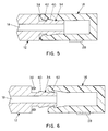
- a central portion 34 of the cold plate 12 containing the fluid channels 18 and 20 projects beyond the adjacent end surface 36 of the outer portion of the cold plate and a gasket 38 is affixed to the end surface 36 as shown in Figs. 5 and 6.
- the end portion 34 of the cold plate has an enlarged ridge 40 with a ramp-shaped outer surface and the headers 14 and 16 have an internal ramped ridge 42 enabling the opposite sides of the header to be forced apart and snapped over the ridge 40 after engaging the gasket 38 so as to retain the seal in a compressed condition against the end surface 36 of the outer portion of the cold plate 12 as shown in Fig. 5. With this mounting arrangement no fasteners are required to attach the headers to the cold plate.
- the end portions 34 of the cold plate 12 and the inner surfaces of the headers have no ramp-like engaging portions but instead are held together by a layer of an adhesive sealing material 46 coated on the end surfaces 36 of the cold plate and the engaging surfaces of the header.
- This arrangement also eliminates the necessity for fasteners to attach the headers to the cold plate.
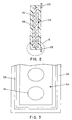
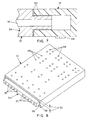
- Fig. 8 illustrates a typical arrangement of mounting holes 48 for electrical and electronic components on the surface of the heat transfer cold plate 12.
- the maximum depth of the holes 48 is represented by the arrows 50 indicating the distance between the upper surface of the heat transfer cold plate 12 and the upper surface of the projection 34 containing the inlet passages 18 and outlet passages 20 to assure that the mounting holes do not intercept those passages.
- the inlet nozzle 22 and outlet nozzle 24 project perpendicularly from the end surface of the inlet/outlet header 14.
- the inlet and outlet nozzles may be angled from one side surface of the inlet/outlet header as indicated by the nozzle 54 shown in Fig. 10. Such angled inlet and outlet nozzles may extend either from the same side on opposite ends of the header and may be on the same surface on which the mounting feet 28 are located or on the opposite side surface.
- heat-generating electrical or electronic components are mounted on one or both surfaces of the cold plate 12 using the threaded mounting holes 48 in such manner as to assure good heat transfer characteristics between the components and the cold plate.
- a coolant such as chilled water or other heat transfer fluid is supplied to the inlet nozzle 22 and flows through the inlet and return passages 18 and 20 at a rate sufficient to remove heat from the cold plate so as to maintain the component at or below a desired maximum temperature. Any heat transfer fluid providing the desired heat transfer characteristics and which does not react with or corrode the cold plate or the headers may be used.
- the circulation rate of the coolant may be controlled automatically, if desired, based on the detected temperature of the surface of the cold plate. Electrical isolation of the mounted electrical and electronic components from any structure on which the cold plate assembly is mounted is assured by the provision of the electrically insulating headers for the cold plate and the use of mounting feet which are attached to the electrically insulating headers.
Landscapes
- Cooling Or The Like Of Electrical Apparatus (AREA)
- Fuel Cell (AREA)
- Cooling Or The Like Of Semiconductors Or Solid State Devices (AREA)
Applications Claiming Priority (2)
| Application Number | Priority Date | Filing Date | Title |
|---|---|---|---|
| US385277 | 1999-08-30 | ||
| US09/385,277 US6230791B1 (en) | 1999-08-30 | 1999-08-30 | Heat transfer cold plate arrangement |
Publications (1)
| Publication Number | Publication Date |
|---|---|
| EP1089604A1 true EP1089604A1 (fr) | 2001-04-04 |
Family
ID=23520749
Family Applications (1)
| Application Number | Title | Priority Date | Filing Date |
|---|---|---|---|
| EP00890262A Withdrawn EP1089604A1 (fr) | 1999-08-30 | 2000-08-30 | Echangeur de chaleur |
Country Status (3)
| Country | Link |
|---|---|
| US (1) | US6230791B1 (fr) |
| EP (1) | EP1089604A1 (fr) |
| JP (1) | JP2001127478A (fr) |
Cited By (8)
| Publication number | Priority date | Publication date | Assignee | Title |
|---|---|---|---|---|
| DE10203238A1 (de) * | 2002-01-28 | 2003-06-05 | Siemens Ag | Kühlbaustein |
| DE10338469A1 (de) * | 2003-08-21 | 2004-11-25 | Siemens Ag | Stromrichtermodul mit einer rückwärtigen Kühlplatte |
| EP1298975A3 (fr) * | 2001-09-26 | 2005-11-16 | Modine Manufacturing Company | Système de refroidissement modulaire et bus thermique d' armoires pour électronique de puissance |
| DE102005048100A1 (de) * | 2005-09-30 | 2007-04-05 | Robert Bosch Gmbh | Elektrisches Gerät, insbesondere elektronisches Steuergerät für Kraftfahrzeuge |
| EP1770775A3 (fr) * | 2005-09-29 | 2008-11-05 | Samsung Electronics Co., Ltd. | Système de refroidissment |
| WO2009113959A1 (fr) * | 2008-03-14 | 2009-09-17 | Danaher Motion Stockholm Ab | Dispositif de refroidissement et son procédé de fabrication |
| DE102013108086B3 (de) | 2013-07-29 | 2014-08-21 | Semikron Elektronik Gmbh & Co. Kg | Anordnung mit einem Leistungshalbleitermodul und einer Kühleinrichtung, Kühlsystem hiermit und Verfahren zur Herstellung der Anordnung |
| CN111760759A (zh) * | 2020-06-29 | 2020-10-13 | 蜂巢能源科技有限公司 | 冷板涂胶装置及方法 |
Families Citing this family (46)
| Publication number | Priority date | Publication date | Assignee | Title |
|---|---|---|---|---|
| US8584738B2 (en) * | 2002-06-14 | 2013-11-19 | Lockheed Martin Corporation | Apparatus and method for extracting heat from a device |
| FR2867608B1 (fr) * | 2004-03-12 | 2006-05-26 | Metal Process | Refroidisseur pour composant electronique de puissance |
| US20060059937A1 (en) * | 2004-09-17 | 2006-03-23 | Perkins David E | Systems and methods for providing cooling in compressed air storage power supply systems |
| US8333330B2 (en) * | 2004-09-17 | 2012-12-18 | Active Power, Inc. | Systems and methods for controlling temperature and pressure of fluids |
| US7314059B2 (en) * | 2004-09-17 | 2008-01-01 | Active Power, Inc. | Systems and methods for controlling pressure of fluids |
| US20060059936A1 (en) * | 2004-09-17 | 2006-03-23 | Radke Robert E | Systems and methods for providing cooling in compressed air storage power supply systems |
| JP4333587B2 (ja) * | 2005-01-14 | 2009-09-16 | 三菱電機株式会社 | ヒートシンクおよび冷却ユニット |
| CN200954444Y (zh) * | 2006-09-27 | 2007-10-03 | 吕仲明 | 径向折流板壳式反应器 |
| JP5332115B2 (ja) * | 2007-02-22 | 2013-11-06 | 三菱マテリアル株式会社 | パワー素子搭載用ユニット |
| TW200839495A (en) * | 2007-03-30 | 2008-10-01 | Cooler Master Co Ltd | Structure of water cooling head |
| JP5194557B2 (ja) * | 2007-05-23 | 2013-05-08 | 三菱マテリアル株式会社 | パワー素子搭載用液冷式冷却器とその製造方法 |
| JP5217246B2 (ja) * | 2007-05-24 | 2013-06-19 | 三菱マテリアル株式会社 | パワーモジュール用ユニットの製造方法 |
| US7911161B2 (en) * | 2007-06-28 | 2011-03-22 | GM Global Technology Operations LLC | Automotive power inverter with reduced capacitive coupling |
| US8490678B2 (en) * | 2008-06-02 | 2013-07-23 | Gerald Ho Kim | Silicon-based thermal energy transfer device and apparatus |
| US20110232887A1 (en) * | 2010-03-29 | 2011-09-29 | Zaffetti Mark A | Cold plate with integral structural fluid port |
| US20110232882A1 (en) * | 2010-03-29 | 2011-09-29 | Zaffetti Mark A | Compact cold plate configuration utilizing ramped closure bars |
| DE102010039676B4 (de) * | 2010-08-24 | 2016-06-09 | Mahle International Gmbh | Kühlsystem zum Kühlen von Elektronikkomponenten |
| KR101173057B1 (ko) | 2010-09-29 | 2012-08-13 | 현대자동차주식회사 | 온도 균일성이 향상되는 연료전지 스택 |
| US8869877B2 (en) | 2010-10-11 | 2014-10-28 | Hamilton Sundstrand Space Systems International, Inc. | Monolithic cold plate configuration |
| WO2012138833A2 (fr) * | 2011-04-05 | 2012-10-11 | A123 Systems, Inc. | Ensemble de refroidissement et procédé de commande |
| US9901008B2 (en) * | 2014-10-27 | 2018-02-20 | Ebullient, Inc. | Redundant heat sink module |
| US9848509B2 (en) | 2011-06-27 | 2017-12-19 | Ebullient, Inc. | Heat sink module |
| US9854715B2 (en) | 2011-06-27 | 2017-12-26 | Ebullient, Inc. | Flexible two-phase cooling system |
| US9854714B2 (en) | 2011-06-27 | 2017-12-26 | Ebullient, Inc. | Method of absorbing sensible and latent heat with series-connected heat sinks |
| US9832913B2 (en) | 2011-06-27 | 2017-11-28 | Ebullient, Inc. | Method of operating a cooling apparatus to provide stable two-phase flow |
| US20150237767A1 (en) * | 2011-06-27 | 2015-08-20 | Ebullient, Llc | Heat sink for use with pumped coolant |
| US9901013B2 (en) | 2011-06-27 | 2018-02-20 | Ebullient, Inc. | Method of cooling series-connected heat sink modules |
| DE102012217870A1 (de) * | 2012-09-28 | 2014-04-17 | Behr Gmbh & Co. Kg | Wärmeübertrager |
| JP6095160B2 (ja) * | 2013-03-28 | 2017-03-15 | 日軽熱交株式会社 | 受熱器 |
| US9504190B2 (en) * | 2013-05-06 | 2016-11-22 | Green Revolution Cooling, Inc. | System and method of packaging computing resources for space and fire-resistance |
| US20160025423A1 (en) * | 2014-07-22 | 2016-01-28 | Hamilton Sundstrand Space Systems International, Inc. | Heat transfer plate |
| AU2015339811A1 (en) * | 2014-10-27 | 2017-06-15 | Ebullient, Llc | Heat sink module |
| US9852963B2 (en) | 2014-10-27 | 2017-12-26 | Ebullient, Inc. | Microprocessor assembly adapted for fluid cooling |
| US10184699B2 (en) | 2014-10-27 | 2019-01-22 | Ebullient, Inc. | Fluid distribution unit for two-phase cooling system |
| US20160120059A1 (en) | 2014-10-27 | 2016-04-28 | Ebullient, Llc | Two-phase cooling system |
| US9891002B2 (en) | 2014-10-27 | 2018-02-13 | Ebullient, Llc | Heat exchanger with interconnected fluid transfer members |
| JP6513427B2 (ja) * | 2015-02-27 | 2019-05-15 | 昭和電工株式会社 | 液冷式冷却装置 |
| KR20170069089A (ko) * | 2015-12-10 | 2017-06-20 | 현대자동차주식회사 | 차량용 라디에이터 |
| JP6646005B2 (ja) * | 2017-03-24 | 2020-02-14 | 株式会社ケーヒン | パワーモジュール |
| JP6646004B2 (ja) * | 2017-03-24 | 2020-02-14 | 株式会社ケーヒン | パワーモジュール |
| CN107314352B (zh) * | 2017-07-09 | 2019-09-10 | 曹建新 | 一种散热型led灯具 |
| JP7117108B2 (ja) * | 2018-01-25 | 2022-08-12 | 三井化学株式会社 | 冷却装置 |
| US10582640B2 (en) * | 2018-05-09 | 2020-03-03 | Hewlett Packard Enterprise Development Lp | Conducting plastic cold plates |
| US11699634B2 (en) * | 2019-05-03 | 2023-07-11 | Applied Materials, Inc. | Water cooled plate for heat management in power amplifiers |
| US10905028B2 (en) * | 2019-05-07 | 2021-01-26 | International Business Machines Corporation | Structure for eliminating the impact of cold plate fouling |
| US12402287B2 (en) | 2020-05-29 | 2025-08-26 | Ovh | Uninterruptible power supply having a liquid cooling device |
Citations (6)
| Publication number | Priority date | Publication date | Assignee | Title |
|---|---|---|---|---|
| US4420739A (en) * | 1980-09-15 | 1983-12-13 | Peter Herren | Liquid-cooled electrical assembly |
| US5111280A (en) * | 1988-11-10 | 1992-05-05 | Iversen Arthur H | Thermal management of power conditioning systems |
| EP0508717A1 (fr) * | 1991-04-08 | 1992-10-14 | General Electric Company | Dissipateur de chaleur intégré pour modules semi-conducteurs |
| WO1997025741A1 (fr) * | 1996-01-04 | 1997-07-17 | Daimler-Benz Aktiengesellschaft | Element de refroidissement avec des ergots |
| EP0858107A1 (fr) * | 1997-02-03 | 1998-08-12 | Ferraz | Echangeur de chaleur pour composants électroniques et appareillages électrotechniques |
| EP0930815A1 (fr) * | 1998-01-19 | 1999-07-21 | Ferraz Date Industries | Composant électronique de puissance et son procédé de fabrication |
Family Cites Families (10)
| Publication number | Priority date | Publication date | Assignee | Title |
|---|---|---|---|---|
| JPS5531204A (en) | 1978-08-23 | 1980-03-05 | Diesel Kiki Co Ltd | Heat exchanger |
| US4758926A (en) * | 1986-03-31 | 1988-07-19 | Microelectronics And Computer Technology Corporation | Fluid-cooled integrated circuit package |
| US4989070A (en) | 1988-11-10 | 1991-01-29 | Coriolis Corporation | Modular heat sink structure |
| US4939624A (en) * | 1988-12-14 | 1990-07-03 | Cray Research, Inc. | Interconnected multiple circuit module |
| US5005640A (en) * | 1989-06-05 | 1991-04-09 | Mcdonnell Douglas Corporation | Isothermal multi-passage cooler |
| US5014904A (en) * | 1990-01-16 | 1991-05-14 | Cray Research, Inc. | Board-mounted thermal path connector and cold plate |
| US5043797A (en) * | 1990-04-03 | 1991-08-27 | General Electric Company | Cooling header connection for a thyristor stack |
| US5099311A (en) * | 1991-01-17 | 1992-03-24 | The United States Of America As Represented By The United States Department Of Energy | Microchannel heat sink assembly |
| US5453911A (en) | 1994-02-17 | 1995-09-26 | General Motors Corporation | Device for cooling power electronics |
| FR2729044B1 (fr) * | 1994-12-30 | 1997-01-24 | Atherm | Element refroisisseur et connecteur pour un composant electronique de puissance refroidi par un fluide electriquement isole du composant |
-
1999
- 1999-08-30 US US09/385,277 patent/US6230791B1/en not_active Expired - Fee Related
-
2000
- 2000-08-30 EP EP00890262A patent/EP1089604A1/fr not_active Withdrawn
- 2000-08-30 JP JP2000261006A patent/JP2001127478A/ja not_active Withdrawn
Patent Citations (6)
| Publication number | Priority date | Publication date | Assignee | Title |
|---|---|---|---|---|
| US4420739A (en) * | 1980-09-15 | 1983-12-13 | Peter Herren | Liquid-cooled electrical assembly |
| US5111280A (en) * | 1988-11-10 | 1992-05-05 | Iversen Arthur H | Thermal management of power conditioning systems |
| EP0508717A1 (fr) * | 1991-04-08 | 1992-10-14 | General Electric Company | Dissipateur de chaleur intégré pour modules semi-conducteurs |
| WO1997025741A1 (fr) * | 1996-01-04 | 1997-07-17 | Daimler-Benz Aktiengesellschaft | Element de refroidissement avec des ergots |
| EP0858107A1 (fr) * | 1997-02-03 | 1998-08-12 | Ferraz | Echangeur de chaleur pour composants électroniques et appareillages électrotechniques |
| EP0930815A1 (fr) * | 1998-01-19 | 1999-07-21 | Ferraz Date Industries | Composant électronique de puissance et son procédé de fabrication |
Cited By (12)
| Publication number | Priority date | Publication date | Assignee | Title |
|---|---|---|---|---|
| EP1298975A3 (fr) * | 2001-09-26 | 2005-11-16 | Modine Manufacturing Company | Système de refroidissement modulaire et bus thermique d' armoires pour électronique de puissance |
| EP2094069A1 (fr) * | 2001-09-26 | 2009-08-26 | Modine Manufacturing Company | Système de refroidissement modulaire et bus thermique d' armoires pour électronique de puissance |
| DE10203238A1 (de) * | 2002-01-28 | 2003-06-05 | Siemens Ag | Kühlbaustein |
| DE10338469A1 (de) * | 2003-08-21 | 2004-11-25 | Siemens Ag | Stromrichtermodul mit einer rückwärtigen Kühlplatte |
| EP1770775A3 (fr) * | 2005-09-29 | 2008-11-05 | Samsung Electronics Co., Ltd. | Système de refroidissment |
| DE102005048100A1 (de) * | 2005-09-30 | 2007-04-05 | Robert Bosch Gmbh | Elektrisches Gerät, insbesondere elektronisches Steuergerät für Kraftfahrzeuge |
| DE102005048100B4 (de) | 2005-09-30 | 2018-07-05 | Robert Bosch Gmbh | Elektrisches Gerät, insbesondere elektronisches Steuergerät für Kraftfahrzeuge |
| WO2009113959A1 (fr) * | 2008-03-14 | 2009-09-17 | Danaher Motion Stockholm Ab | Dispositif de refroidissement et son procédé de fabrication |
| DE102013108086B3 (de) | 2013-07-29 | 2014-08-21 | Semikron Elektronik Gmbh & Co. Kg | Anordnung mit einem Leistungshalbleitermodul und einer Kühleinrichtung, Kühlsystem hiermit und Verfahren zur Herstellung der Anordnung |
| CN104347545A (zh) * | 2013-07-29 | 2015-02-11 | 赛米控电子股份有限公司 | 具有大功率半导体模块和冷却装置的结构、冷却系统以及制造该结构的方法 |
| CN104347545B (zh) * | 2013-07-29 | 2018-11-02 | 赛米控电子股份有限公司 | 具有大功率半导体模块和冷却装置的结构、冷却系统以及制造该结构的方法 |
| CN111760759A (zh) * | 2020-06-29 | 2020-10-13 | 蜂巢能源科技有限公司 | 冷板涂胶装置及方法 |
Also Published As
| Publication number | Publication date |
|---|---|
| JP2001127478A (ja) | 2001-05-11 |
| US6230791B1 (en) | 2001-05-15 |
Similar Documents
| Publication | Publication Date | Title |
|---|---|---|
| US6230791B1 (en) | Heat transfer cold plate arrangement | |
| US10475724B2 (en) | Heat exchangers for dual-sided cooling | |
| EP1384271B1 (fr) | Systeme electrique de refroidissement | |
| US12178019B2 (en) | Coolant system for a busbar assembly | |
| US11876203B2 (en) | Heat exchanger with integrated support structure | |
| US8391008B2 (en) | Power electronics modules and power electronics module assemblies | |
| EP0107706B1 (fr) | Module de refroidissement par tubes de dissipation de chaleur pour des plaques de circuit de grande puissance | |
| US11984572B2 (en) | Battery cooling system | |
| US4958257A (en) | Heat conducting interface for electronic module | |
| KR101934592B1 (ko) | 전력반도체 시스템 | |
| US5349498A (en) | Integral extended surface cooling of power modules | |
| EP1804014B1 (fr) | Unité de distribution d'écoulement et unité de refroidissement | |
| AU716635B2 (en) | Thermoelectric apparatus | |
| US8451609B2 (en) | Cooling device for a plurality of power modules | |
| US20050128705A1 (en) | Composite cold plate assembly | |
| CN101610664B (zh) | 液体冷却器及其制造方法 | |
| US20010040025A1 (en) | Heat exchanger element | |
| US11571950B2 (en) | Heating device | |
| KR20120091326A (ko) | 에너지 저장 디바이스 | |
| EP0838867A2 (fr) | Module thermoélectrique | |
| CN112762752A (zh) | 改良型集液槽及多流道液冷排 | |
| RU2179768C2 (ru) | Термоэлектрический модуль | |
| CN222905173U (zh) | 一种散热装置和打印设备 | |
| US20260009567A1 (en) | Cooling device using thermoelectric elelment | |
| KR102343882B1 (ko) | 반도체 공정용 칠러시스템 |
Legal Events
| Date | Code | Title | Description |
|---|---|---|---|
| PUAI | Public reference made under article 153(3) epc to a published international application that has entered the european phase |
Free format text: ORIGINAL CODE: 0009012 |
|
| AK | Designated contracting states |
Kind code of ref document: A1 Designated state(s): DE FR GB IT |
|
| AX | Request for extension of the european patent |
Free format text: AL;LT;LV;MK;RO;SI |
|
| 17P | Request for examination filed |
Effective date: 20010816 |
|
| AKX | Designation fees paid |
Free format text: DE FR GB IT |
|
| STAA | Information on the status of an ep patent application or granted ep patent |
Free format text: STATUS: THE APPLICATION IS DEEMED TO BE WITHDRAWN |
|
| 18D | Application deemed to be withdrawn |
Effective date: 20050301 |