EP1089832B1 - Vorrichtung zur vorbehandlung von oberflächen - Google Patents
Vorrichtung zur vorbehandlung von oberflächen Download PDFInfo
- Publication number
- EP1089832B1 EP1089832B1 EP99924302A EP99924302A EP1089832B1 EP 1089832 B1 EP1089832 B1 EP 1089832B1 EP 99924302 A EP99924302 A EP 99924302A EP 99924302 A EP99924302 A EP 99924302A EP 1089832 B1 EP1089832 B1 EP 1089832B1
- Authority
- EP
- European Patent Office
- Prior art keywords
- end effector
- felt
- fluid
- ribbon
- application tip
- Prior art date
- Legal status (The legal status is an assumption and is not a legal conclusion. Google has not performed a legal analysis and makes no representation as to the accuracy of the status listed.)
- Expired - Lifetime
Links
- 238000002360 preparation method Methods 0.000 title description 3
- 239000012636 effector Substances 0.000 claims abstract description 90
- 239000012530 fluid Substances 0.000 claims abstract description 53
- 238000004140 cleaning Methods 0.000 claims abstract description 41
- 230000033001 locomotion Effects 0.000 claims abstract description 27
- 239000007767 bonding agent Substances 0.000 claims abstract description 6
- 230000007246 mechanism Effects 0.000 claims description 12
- 230000026058 directional locomotion Effects 0.000 claims 4
- 239000000356 contaminant Substances 0.000 abstract description 6
- 239000000853 adhesive Substances 0.000 abstract description 4
- 230000001070 adhesive effect Effects 0.000 abstract description 4
- 229920001971 elastomer Polymers 0.000 abstract 1
- 239000000806 elastomer Substances 0.000 abstract 1
- 238000012544 monitoring process Methods 0.000 abstract 1
- 230000005540 biological transmission Effects 0.000 description 10
- 230000008901 benefit Effects 0.000 description 5
- 238000010276 construction Methods 0.000 description 5
- 239000003921 oil Substances 0.000 description 5
- 239000011521 glass Substances 0.000 description 4
- KFZMGEQAYNKOFK-UHFFFAOYSA-N Isopropanol Chemical compound CC(C)O KFZMGEQAYNKOFK-UHFFFAOYSA-N 0.000 description 3
- 238000013023 gasketing Methods 0.000 description 3
- 230000013011 mating Effects 0.000 description 3
- 230000000694 effects Effects 0.000 description 2
- 239000004744 fabric Substances 0.000 description 2
- 239000004519 grease Substances 0.000 description 2
- 238000004519 manufacturing process Methods 0.000 description 2
- 239000000463 material Substances 0.000 description 2
- 238000000034 method Methods 0.000 description 2
- 230000037452 priming Effects 0.000 description 2
- 239000002904 solvent Substances 0.000 description 2
- 230000007704 transition Effects 0.000 description 2
- 230000002745 absorbent Effects 0.000 description 1
- 239000002250 absorbent Substances 0.000 description 1
- 230000008878 coupling Effects 0.000 description 1
- 238000010168 coupling process Methods 0.000 description 1
- 238000005859 coupling reaction Methods 0.000 description 1
- 230000001419 dependent effect Effects 0.000 description 1
- 238000005516 engineering process Methods 0.000 description 1
- 238000001704 evaporation Methods 0.000 description 1
- 239000000203 mixture Substances 0.000 description 1
- 238000003825 pressing Methods 0.000 description 1
- 230000009257 reactivity Effects 0.000 description 1
- 230000009467 reduction Effects 0.000 description 1
- 238000003860 storage Methods 0.000 description 1
- XLYOFNOQVPJJNP-UHFFFAOYSA-N water Substances O XLYOFNOQVPJJNP-UHFFFAOYSA-N 0.000 description 1
- 210000000707 wrist Anatomy 0.000 description 1
Images




Classifications
-
- B—PERFORMING OPERATIONS; TRANSPORTING
- B08—CLEANING
- B08B—CLEANING IN GENERAL; PREVENTION OF FOULING IN GENERAL
- B08B1/00—Cleaning by methods involving the use of tools
- B08B1/10—Cleaning by methods involving the use of tools characterised by the type of cleaning tool
- B08B1/16—Rigid blades, e.g. scrapers; Flexible blades, e.g. wipers
-
- B—PERFORMING OPERATIONS; TRANSPORTING
- B05—SPRAYING OR ATOMISING IN GENERAL; APPLYING FLUENT MATERIALS TO SURFACES, IN GENERAL
- B05C—APPARATUS FOR APPLYING FLUENT MATERIALS TO SURFACES, IN GENERAL
- B05C1/00—Apparatus in which liquid or other fluent material is applied to the surface of the work by contact with a member carrying the liquid or other fluent material, e.g. a porous member loaded with a liquid to be applied as a coating
- B05C1/04—Apparatus in which liquid or other fluent material is applied to the surface of the work by contact with a member carrying the liquid or other fluent material, e.g. a porous member loaded with a liquid to be applied as a coating for applying liquid or other fluent material to work of indefinite length
- B05C1/14—Apparatus in which liquid or other fluent material is applied to the surface of the work by contact with a member carrying the liquid or other fluent material, e.g. a porous member loaded with a liquid to be applied as a coating for applying liquid or other fluent material to work of indefinite length using a travelling band
-
- B—PERFORMING OPERATIONS; TRANSPORTING
- B08—CLEANING
- B08B—CLEANING IN GENERAL; PREVENTION OF FOULING IN GENERAL
- B08B1/00—Cleaning by methods involving the use of tools
- B08B1/30—Cleaning by methods involving the use of tools by movement of cleaning members over a surface
-
- B—PERFORMING OPERATIONS; TRANSPORTING
- B08—CLEANING
- B08B—CLEANING IN GENERAL; PREVENTION OF FOULING IN GENERAL
- B08B1/00—Cleaning by methods involving the use of tools
- B08B1/40—Cleaning tools with integrated means for dispensing fluids, e.g. water, steam or detergents
-
- B—PERFORMING OPERATIONS; TRANSPORTING
- B08—CLEANING
- B08B—CLEANING IN GENERAL; PREVENTION OF FOULING IN GENERAL
- B08B5/00—Cleaning by methods involving the use of air flow or gas flow
- B08B5/02—Cleaning by the force of jets, e.g. blowing-out cavities
Definitions
- the present invention relates generally to a device used to clean, prime or otherwise prepare a surface onto which a gasket, adhesive or other bonding agent is to be applied. More particularly, the present invention relates to a robotic arm end effector which is used to prepare such a surface having complex geometry.
- gaskets adhesives and other types of bonding agents to provide a sealed interface between two mating components, as well as to adhere one component to another component
- gaskets are widely used for a variety of purposes.
- Common uses for gaskets in the automotive industry include effecting a seal between components such as the transmission case and the transmission pan or an engine block and oil pan, rocker cover or similar covers.
- Other purposes may include the use of gasket-type adhesives to secure automobile glass.
- the gasket is applied to one of the components by forming the gasket directly on the component prior to assembly.
- This technique is known as formed-in- place (FIP) gasketing.
- FIP formed-in- place
- the art has seen the use of various robotically controlled devices to clean or prime automotive windshield glass. These robotic machines apply a cleaning fluid or along a path traced by the robotic machine over the component surface.
- the robotic machine also provides a wiping device, such as a felt strip, which follows the applied fluid to wipe the fluid along the traced path.
- a wiping device such as a felt strip
- These robotically controlled cleaning devices serve adequately where the surface is of relatively simple geometry such as that found with automobile glass. With complex parts, such as for example, the flange on a transmission, existing robotically controlled cleaning devices cannot take advantage of the full range of motion of the robot due to their size and configuration. Many of these devices rely on "drip and drag" technology where the solvent is applied at a location spaced 5-6.4cm (2-21 ⁇ 2 inches) from the felt. These existing devices can not adequately clean complex surfaces where the device is required to make many turns and thus cannot accurately traverse the path onto which the gasket must be applied. This may result in incomplete cleaning of the surface and resultant poor adhesion of the subsequently applied gasket on the surface.
- UK Patent Application no. GB 2 290 463 A describes a robotic device movable three-dimensionally for cleaning a surface of a vehicle glass panel before application of primer.
- the device includes a robotic arm with a wiper mounted on its distal end and movable along the surface of the panel; a reel for holding a coiled web of wiping materialwhile allowing the web to be pulled out; a clamp for releasably clamping a leading end of the web which is pulled out of the reel; a presser for pressing a portion of the web slidably in contact with the surface of the panel while tensioning the web between the reel and the clamp when the wiper is moving along the surface of the panel; a nozzle for supplying wiping solution (cleaning fluid) to the surface of the panel before the web slides on the surface of the panel and a gripper for pulling the distal end of the web out of the clamp when the web is released from the clamp after the surface of the panel has been wiped.
- wiping solution cleaning fluid
- the cleaning device must remove a significant amount of surface contaminants.
- the cleaning device in the application of gasketing in an automatic transmission situation, the cleaning device must remove residual automatic transmission fluid which drains out onto the flange surface in test operations. As may be appreciated, the wiping felt thus absorbs the automatic transmission fluid. In order to effectively clean the entire surface, it is necessary to present clean felt to the surface to be cleaned. The cleaning device must therefore permit continuous feeding of clean felt to the head of the device to assure complete cleaning of the surface being traversed.
- Existing heads have limited felt storage capacity. Furthermore, even where a supply of additional felt is provided, the existing heads do not accurately or continually advance the felt so as to present a continuous clean felt portion in contact with the surface to be cleaned.
- the present invention provides an apparatus for preparing a surface as disclosed in claim 1 and a robotically mounted end effector for preparing a surface as disclosed in claims 10,19.
- the end effector is biased so as to provide constant pressure against the flange surface to assure continuous uniform wiping of the fluid-wetted felt across the flange surface. Movement of the end effector by the robotic arm as well as advancement of the felt, application of cleaning fluid, and pressure sensing is controlled and monitored by a preprogrammed numeric controller.
- the present invention provides a robotically controlled device for cleaning, priming or otherwise preparing a flange or mating surface (hereinafter referred to as a flange surface).
- a flange surface a flange surface
- the device of the present invention allows for the cleaning of a surface having complex geometry such as that found in automotive applications, particularly in gasketing situations associated with engine blocks and automatic transmissions.
- the cleaning device of the present invention deposits a cleaning fluid directly onto a continuously advanced supply of felt which wipes the fluid on the surface to be cleaned.
- the device Prior to wiping the fluid on the surface, the device wipes a squeegee-like knife along the surface to remove residually deposited oils, fluids or other contaminants. Immediately after applying the felt-applied fluid, an air knife force-flashes off the fluid.
- the device of the present invention allows continuous feeding of felt under tension from a remote supply and the continuous escapement of felt under tension to a remote collection container, thus enabling the device to continually operate in an automated assembly environment. Furthermore, the device includes a novel end effector which is relatively small and light weight. The construction and operation of the end effector allows the end effector to take full advantage of the six axes of motion which is provided by the robotic device to which it is attached.
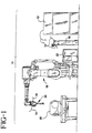
- Apparatus 10 includes a felt supply 12 for supplying a ribbon of felt 14 therefrom.
- Felt 14 is an elongate ribbon of absorbent felt-like cloth having a width of approximately 1.9cm (3 ⁇ 4") and a thickness of approximately 0.24 cm (3/32").
- the felt 14 is a fabric material formed into a ribbon-like structure and is commonly used for wiping a cleaning fluid to a surface.
- a large quantity of felt is housed within felt supply 12 which may be a spool or other container which permits the continuous feeding of felt 14 therefrom.
- Felt 14 is fed from supply 12 to a tension device 16. As will be described in further detail hereinbelow, the tension device maintains the ribbon of felt 14 under tension throughout the movement of felt during the cleaning operation.
- a robotic device 18 which moves an end effector 20 through six axes of motion under the control of a numeric controller 22.
- the robotic device 18 is a conventional six axis modular construction electric servo-driven robot, the movement of which is directed by preprogrammed numeric controller 22.
- Examples of commercially available robotic devices which may be used in combination with the present invention include a 3-axis adept gantry style robot as well as 6-axis robotic devices such as those supplied by Fanuc Robotics under the trade designation M-710i/iW and A.B.B. Robotics Products under the trade designation IRB 4400.
- the robotic device must be capable of providing at least four, preferably six, geometrically dependent axes of motion so that the end effector can traverse the complex geometric path dictated by the motion program supplied to the numeric controller.
- Such capabilities allow the end effector to provide complete cleaning of a gasket-bearing surface having complex geometry such as that found in automotive applications including flanges in engine block, automatic transmission, and axle applications.
- the end effector 20 of the present invention is of construction which takes full advantage of the six axes of motion provided by the robotic device. It may be appreciated that, depending upon the application, it may necessary for the end effector to have full range of motion with respect to both linear and rotational movement.
- a component which is to be cleaned such as an engine or transmission
- the end effector will be lowered to contact a flange surface 35 that requires cleaning.
- the robotic device will move the end effector along the flange surface to effect cleaning of the surface.
- the robotic device will then remove the end effector from the component to a stand-by position where, in a continuous operation, another component may be moved to the device for sequential cleaning.
- the numeric controller 22 In addition to providing preprogrammed movement of the end effector by way of the robotic device, the numeric controller 22 also provides direction for controlled surface pressure of the end effector against the flange surface. Such preprogrammed control surface pressure assures repeatable engineered contact between the felt which is cleaning the surface and the surface itself to assure complete cleaning of the flange path. Furthermore, as will be described in further detail hereinbelow, the numeric controller 22 may also be used to advance the felt through the end effector to provide a consistently clean felt surface portion.
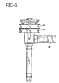
- End effector 20 is an elongate member which is mounted by a mounting surface 30 to the wrist portion of the robotic device 18 shown in Figure 1.
- End effector 20 has an elongate central member 32 having an upper mounting end 32a and a lower application end 32b terminating in a rounded application tip 33.
- Central member 32 includes a centrally located fluid channel 34 which is fed by a fluid conduit 36a which supplies a suitable cleaning fluid from a remote location (not shown).
- the cleaning fluid may include a mixture of water and isopropyl alcohol and more specifically may be of the type sold by Loctite Corporation under the trade designation CLEANER 7070.
- Fluid channel 34 maybe formed to have a dispense opening 34a adjacent lower end 32b through central member 32. More preferably as shown in Figure 2A, the dispense opening 34a may extend through application tip 33. In the embodiment of Figure 2A, dispense opening 34a is located proximate of the distal end of the rounded application tip 33 so that fluid is dispensed through the side of application tip 33. Also as shown in Figure 2A the dispensing of fluid from opening 34a maybe further controlled by employing a ball check 34b within channel 34. The ball check 34b helps maintain fluid in channel 34 as well as helps modulate the dispensing of fluid through opening 34a.
- the end effector 20 accommodates a continuously movable length of felt 14 supplied under tension from felt supply 12 through tension device 16.
- the felt 14 is supplied to a pair of non-overlapping 360-degree rotating drums 40 which function as transition devices to positionally orient the felt so that it is properly positioned with respect to rounded application tip 33.
- An adjacent exit drum 42 is provided so as to transition used felt after it has progressed about rounded application tip 33.
- Movement of felt 14 is provided by a drive mechanism 45 including a servo motor and gear reduction which extends laterally from the central member 32 of end effector 20.
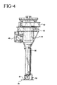
- Figures 2 and 2A show different constructions of drive mechanism 45.
- the drive mechanism 45 of Figure 2A provides for more precision control of felt advancement preventing over tensioning or under tensioning of the felt.
- Drive mechanism 45 pulls the ribbon of felt 14 under tension from its entry position with respect to entry drum 40 along central member 32 and around rounded application tip 33.
- the drive mechanism 45 driven by instructions received from numeric controller 22, provides for the advancement of felt 14 so as to provide a continuously cleaned felt portion to the flange surface.
- the drive mechanism 45 may further include other structural components such as wheels, gears and the like which effect constant tension and advancement of the felt.
- Tension device 16 accommodates the entry of felt from felt supply 12 at an upper end thereof.
- the ribbon of felt is advanced so as to be wrapped around a dancer wheel 47 which is vertically movable on a friction-free slide on stanchion 48 of tension device 16.
- the dancer wheel 47 may be optionally enclosed by a housing which protects movement of the dancer wheel 47.
- the ribbon of felt travels through a controlled advancement device 49 which maintains sufficient felt length within tension device 16 as the felt is advanced by drive mechanism 45 through end effector 20.
- the tension device 16 including dancer wheel47 and advancement device 49 assures controlled felt tension so as to permit the advance of felt by drive mechanism 45.
- a further similar dancer wheel device (not shown) is used to retract contaminated felt under controlled tension after movement across end effector 20.
- the end effector may optionally include a elongate sinusoidal spring 50 so as to maintain the felt against the body of central member 32.
- the application of fluid to felt 14 may also be controlled by numeric controller 22 ( Figure 1) so that a preprogrammed amount of fluid may be applied to the flange surface.
- the fluid-wetted felt passes beneath rounded application tip 33 where it wipes the flange surface 35 as the end effector moves along a predetermined path defining the flange surface.
- the end effector 20 additionally provides a squeegee 51 mounted adjacent rounded application tip 33.
- Squeegee 51 may include an elastomeric member which is mounted on the leading side of movement of end effector 20 so that prior to the fluid-wetted felt applying fluid to the flange surface, the squeegee 51 wipes along the flange surface 35 removing a certain amount of debris, contaminant, oils and grease which may be on the flange surface. Thereafter the fluid-wetted felt wipes the fluid onto the flange surface further cleaning and priming the flange surface.
- an air knife 52 is provided on the trailing side of end effector 20 adjacent the rounded application tip 33. Shown in more detail in Figure 2A, air knife 52 directs a directional flow of air or other gas to the now cleaned flange surface to force-flash off any residual fluid applied by the fluid-wetted felt 14.
- the air knife may be attached to the end effector with a quick disconnect coupling so as to facilitate replacement of the air knife.
- a take-up tension device (not shown).
- a remote collection hopper or container (also not shown) may be used to accumulate the used felt.
- the take-up tension device is substantially similar to tension device 16, including a stanchion or housing and a dancer wheel.
- the take-up device maintains felt tension on the escapement side of end effector 20 disposing contaminated felt within the remote collection container.
- a conventional photoelectric eye or proximity sensor may be employed with the take-up tension device to signal stoppage of the feeding or escapement when appropriate. Thus tension of the felt is maintained continually across end effector 20 as the felt is moved across application tip 33.
- the central member 32 is movably supported to the mounting portion 30.
- Surface pressure may be controlled by conventional bias spring 54.
- the spring allows movement of the central member with respect to mounting portion 30 so that engineered pressure may be placed against the flange surface 35 during cleaning. Movement of the central member with respect to mounting portion 30 may be monitored by numeric controller 22 so as to provide an accurate indication that proper contact is maintained between the felt 14 about application tip 33 and the flange surface. This feature assures that the entire flange surface is repeatably cleaned while providing quality feedback for fault-free production.
- the end effector 20 of the present invention thus provides certain features not heretofore found in available devices. These features include the ability to centrally feed fluid from a remote supply directly onto the felt just prior to the advancing felt coming in contact with the flange surface.
- the end effector further provides for the controlled continuous advancement of the felt as the felt is traversing its path along the flange surface so that a perpetually clean portion of the felt is exposed to the flange surface.
- the rate of advancement of the felt, the surface pressure, and the amount of fluid disposed on the felt may be controlled by numeric controller 22 so as to provide fully programmable surface preparation characteristics.
- numeric controller 22 so as to provide fully programmable surface preparation characteristics.
- the end effector 20 provides engineered cleaning or preparation of the flange surface along a complex geometry such as may be presented in automotive applications. Since the fluid is deposited directly through the felt onto the flange surface, instead of dripped or sprayed by an offset dispenser, the end effector of the present invention permits utilization of the full range of motion of the robotic device. As the flange surface is wiped by fluid-soaked felt, the end effector may be applied to the flange surface in any attitude including vertically up, vertically down or horizontal. This allows cleaning of the complex flange surfaces found in certain applications. Further, enhanced cleaning of the flange surface is achieved by applying a leading in advance of fluid-wetted felt to preclean the surface. Additionally, a trailing air knife dries the clean surface evaporating fluid.
- End effector 20' is substantially similar to end effector 20 described above. Similar reference numerals are used to denote similar components.
- the central member 32' is movable with respect to mounting portion 30' under the bias of an annular diaphragm 54'.
- Diaphragm 54' provides for biasing the rounded applicator tip 33' against the flange surface to provide externally controllable pressure on the flange surface as described above.
- the end effector 20' is modified from the device shown above by providing a further arrangement for the accurate positioning and transporting of the ribbon of felt 14' with respect to the applicator tip 33'.
- the felt is progressed through an entry member 40' which is a channel-like device supporting a plurality of rollers 41' at the lower end thereof.
- the felt 14' is passed from the tension device 16 (Fig. 1) through the entry device 40' where it is accurately aligned with respect to the lower end of central member 32' of end effector 20'.
- the drive mechanism 45' After the felt 14' has been pulled through the drive mechanism 45' it is positioned within an exit device 42 on the opposite of end effector 20'. Exit device 42 accommodates the used felt 14 through a pair of lower mounted rollers 43'.
Landscapes
- Cleaning In General (AREA)
- Coating Apparatus (AREA)
- Soil Working Implements (AREA)
- Processing Of Meat And Fish (AREA)
- Gasket Seals (AREA)
Claims (19)
- Apparatur (10) zum Vorbehandeln einer Oberfläche (35), auf die ein Dichtungselement, Bindemittel oder dergleichen aufgebracht wird, umfassend:eine Robotervorrichtung (18), die sich entlang mehrerer Achsen bewegen kann;einen Endeffektor (20;20'), der von der Robotervorrichtung (18) getragen wird, zur Bewegung entlang der Oberfläche (35);eine Filzversorgungseinrichtung (12), die entfernt von der Robotervorrichtung angeordnet ist, zum kontinuierlichen Abgeben von Filz (14) an den Endeffektor (20;20') unter Spannung und zum Zurückziehen des Filzes von dem Endeffektor unter Spannung; undein Reinigungsfluidabgabesystem zum Aufstreichen eines Reinigungsfluids direkt auf den Filz (14) an dem Endeffektor (20;20').
- Apparatur (10) nach Anspruch 1, weiter umfassend eine Wischvorrichtung (51), die durch den Endeffektor (20;21') getragen wird, zum Abwischen der Oberfläche (35).
- Apparatur (10) nach Anspruch 2, bei der die Wischvorrichtung (51) ein Abstreifer ist.
- Apparatur (10) nach Anspruch 1 oder Anspruch 2, weiter umfassend ein Luftmesser (52), das durch den Endeffektor (20;20') getragen wird, zum Zwangsvertreiben des aufgestrichenen Fluids.
- Apparatur (10) nach Anspruch 4, bei der die Wischvorrichtung (51) auf dem Endeffektor (20;20') nach vorne zu von seiner Bewegungsrichtung positioniert ist und bei der das Luftmesser (52) auf dem Endeffektor (20;20') nach hinten zu von seiner Bewegungsrichtung positioniert ist.
- Apparatur (10) nach einem vorangehenden Anspruch, bei der die Filzversorgungseinrichtung (12) eine Zufuhrspannvorrichtung (16) umfasst, um ein Maß an lockerem Filz an den Endeffektor zu liefern.
- Apparatur (10) nach einem vorangehenden Anspruch, bei der die Filzversorgungseinrichtung (12) eine Aufwickelspannvorrichtung zum Zurückziehen von Filz (14) unter Spannung umfasst.
- Apparatur (10) nach Anspruch 7, weiter umfassend einen Antriebsmechanismus, der in Kombination mit der Zufuhrspannvorrichtung (16) und Aufwickelspannvorrichtung betreibbar ist, um den Filz (14) abzugeben und zurückzuziehen.
- Apparatur (10) nach Anspruch 1, bei der die Robotervorrichtung (18), der Endeffektor (20;20'), die Filzversorgungseinrichtung (12) und das Reinigungsfluidabgabesystem unter der Steuerung einer numerischen Steuereinrichtung (22) betreibbar sind.
- Roboterartig montierter Endeffektor (20;20') zum Vorbehandeln einer Oberfläche (35), auf die ein Dichtungselement, Bindemittel oder dergleichen aufgebracht wird, umfassend:wobei der Endeffektorkörper einen mittigen langgestreckten Reinigungsfluidkanal (32,32') aufweist, der eine zu der distalen Auftragspitze (33,33') benachbarte Abgabeöffnung (34a) zum Abgeben von Reinigungsfluid auf das Filzband (14) definiert.einen langgestreckten Endeffektorkörper mit einer distalen Auftragspitze (33,33') und eine Einrichtung (12), um ein Filzband (14) kontinuierlich entlang der Auftragspitze vorwärts zu bewegen;
- Endeffektor nach Anspruch 10, bei dem die Abgabeöffnung (34a) positioniert ist, um auf das sich vorwärts bewegende Filzband (14) kontinuierlich Fluid aufzubringen.
- Endeffektor nach Anspruch 10 oder Anspruch 11, bei dem die Auftragspitze (33,33') des Endeffektors (20;20') über die Oberfläche bewegbar ist, um das fluidhaltige Filzband (14) über die Oberfläche (35) zu wischen.
- Endeffektor nach Anspruch 11 oder Anspruch 12, umfassend eine Einrichtung zum Ausrichten des Filzbandes (14) in Bezug zur Auftragspitze (33,33').
- Endeffektor nach Anspruch 13, bei dem die Ausrichteinrichtung umfasst:eine Eintrittstrommel (40) zum Tragen des Filzbandes (14), das sich in Richtung auf die Auftragspitze (33;33') vorwärts bewegt, und eine Austrittstrommel (42) zum Tragen des fluidhaltigen Bandes (14), das sich von der Auftragspitze (33;33') vorwärts bewegt.
- Endeffektor nach Anspruch 13 oder Anspruch 14, bei dem die Ausrichteinrichtung umfasst: ein Eintrittselement, das eine Mehrzahl von Eintrittsrollen zum Tragen des Filzbandes (14) umfasst, das sich in Richtung auf die Auftragspitze vorwärts bewegt, und ein Austrittselement, das eine Mehrzahl von Austrittsrollen zum Tragen des fluidhaltigen Bandes (14) umfasst, das sich von der Auftragspitze (33;33') vorwärts bewegt.
- Endeffektor nach einem der Ansprüche 10 bis 15, bei dem der Endeffektorkörper in Bezug zu einem Montageelement (30;30') bewegbar ist, um für einen vorgespannten Eingriff der Auftragspitze (33;33') gegen die Oberfläche (35) zu sorgen.
- Endeffektor nach Anspruch 16, bei dem der Effektorkörper gegen die Oberfläche (35) federvorgespannt ist.
- Endeffektor nach Anspruch 17, weiter umfassend ein Diaphragma (54') zwischen dem Montageelement (30;30') und dem Endeffektorkörper, um die Federvorspannung zu liefern.
- Roboterartig montierter Endeffektor (20;20') zum Vorbehandeln einer verunreinigten Oberfläche (35), auf die ein Dichtungselement, Bindemittel oder dergleichen aufgebracht werden soll, umfassend:einen langgestreckten Endeffektorkörper mit einer distalen Spitze (33;33') für eine Bewegungsrichtung entlang der Oberfläche (35);ein mit Fluid benetztes Filzband (14), das sich kontinuierlich über die distale Spitze (33;33') vorwärts bewegen lässt, um Reinigungsfluid auf die Oberfläche aufzubringen;eine abstreiferartige Wischvorrichtung (51), die auf dem Endeffektorkörper nach vorne von der Bewegungsrichtung des Endeffektors (20;20') positioniert ist, um die verunreinigte Oberfläche (35) zu wischen; undein Luftmesser (52), das auf dem Endeffektor (20;20') positioniert ist, zum Zwangsvertreiben von Fluid, das durch das Filzband (14) aufgebracht ist.
Applications Claiming Priority (3)
| Application Number | Priority Date | Filing Date | Title |
|---|---|---|---|
| US8598698P | 1998-05-19 | 1998-05-19 | |
| US85986P | 1998-05-19 | ||
| PCT/US1999/010897 WO1999059739A1 (en) | 1998-05-19 | 1999-05-18 | Device for providing surface preparation |
Publications (2)
| Publication Number | Publication Date |
|---|---|
| EP1089832A1 EP1089832A1 (de) | 2001-04-11 |
| EP1089832B1 true EP1089832B1 (de) | 2003-07-30 |
Family
ID=22195241
Family Applications (1)
| Application Number | Title | Priority Date | Filing Date |
|---|---|---|---|
| EP99924302A Expired - Lifetime EP1089832B1 (de) | 1998-05-19 | 1999-05-18 | Vorrichtung zur vorbehandlung von oberflächen |
Country Status (10)
| Country | Link |
|---|---|
| US (1) | US6292976B1 (de) |
| EP (1) | EP1089832B1 (de) |
| JP (1) | JP2002515334A (de) |
| KR (1) | KR20010043123A (de) |
| AT (1) | ATE246051T1 (de) |
| AU (1) | AU752120B2 (de) |
| BR (1) | BR9910557A (de) |
| CA (1) | CA2332854A1 (de) |
| DE (2) | DE69910028T2 (de) |
| WO (1) | WO1999059739A1 (de) |
Cited By (1)
| Publication number | Priority date | Publication date | Assignee | Title |
|---|---|---|---|---|
| US11845103B2 (en) | 2021-09-09 | 2023-12-19 | The Boeing Company | Liquid applicators and methods of applying liquid to a substrate using the same |
Families Citing this family (11)
| Publication number | Priority date | Publication date | Assignee | Title |
|---|---|---|---|---|
| US6695917B2 (en) * | 2001-11-14 | 2004-02-24 | Nordson Corporation | Flow through felt dispenser |
| DE10230021C1 (de) * | 2002-07-04 | 2003-07-10 | Daimler Chrysler Ag | Verfahren zum Reinigen eines Bauteils und geeignete Reinigungsvorrichtung |
| JP2006192392A (ja) * | 2005-01-14 | 2006-07-27 | Honda Motor Co Ltd | ウインドガラス接着剤塗布の前処理装置及びその方法 |
| US8375888B2 (en) * | 2007-05-07 | 2013-02-19 | Intermolecular, Inc. | Apparatus for forming films on substrates |
| US8651046B1 (en) * | 2010-07-23 | 2014-02-18 | The Boeing Company | Robotic sealant and end effector |
| US10040101B2 (en) * | 2015-01-23 | 2018-08-07 | The Boeing Company | Robotic surface-cleaning assemblies and methods |
| DE102015109419A1 (de) * | 2015-06-12 | 2016-12-15 | Dr. Ing. H.C. F. Porsche Aktiengesellschaft | Verfahren zum Reinigen einer Dichtfläche eines Bauteils |
| US10029273B2 (en) | 2015-06-30 | 2018-07-24 | Toyota Motor Engineering & Manufacturing North America, Inc. | End effector cleaning devices and systems |
| HUE062701T2 (hu) * | 2019-12-16 | 2023-11-28 | Lvp Eng & Constructions Bvba | Eszköz és eljárás tartályok tisztítására |
| US12094740B2 (en) * | 2021-03-25 | 2024-09-17 | Applied Materials, Inc. | Automated dry-in dry-out dual side polishing of silicon substrates with integrated spin rinse dry and metrology |
| FI20245177A1 (en) * | 2024-02-16 | 2025-08-17 | Spinnova Oyj | Device and method for treating a metal surface |
Family Cites Families (11)
| Publication number | Priority date | Publication date | Assignee | Title |
|---|---|---|---|---|
| US2330208A (en) * | 1939-11-08 | 1943-09-28 | Stratmore Company | Method and apparatus for belt surfacing |
| US4757763A (en) * | 1979-04-19 | 1988-07-19 | Baldwin Technology Corporation | Automatic blanket cylinder cleaner |
| JPH02227177A (ja) | 1989-01-17 | 1990-09-10 | Techno Roll Kk | 基材表面清掃装置 |
| DE59000587D1 (de) * | 1989-04-05 | 1993-01-28 | Kuka Schweissanlagen & Roboter | Verfahren und vorrichtung zum reinigen von fahrzeugteilen, insbesondere fahrzeugscheiben. |
| GB2290463B (en) * | 1992-03-30 | 1996-02-28 | Honda Motor Co Ltd | Surface Wiping Apparatus |
| US5491871A (en) * | 1993-12-08 | 1996-02-20 | Delco Electronics Corp. | Solder paste and conductive ink printing stencil cleaner |
| US5542143A (en) * | 1994-12-27 | 1996-08-06 | Jem-Yuan; Lin | Circularly cleaning swab structure |
| CA2169236C (en) * | 1995-02-18 | 2002-01-29 | Okie Tani | Device for cleaning screen plate used in screen printing |
| US5519914A (en) | 1995-08-01 | 1996-05-28 | Egan; Ronald G. | Contact type automatic roll cleaner |
| US5926894A (en) * | 1997-01-08 | 1999-07-27 | Justin; Louis K. | Apparatus for preparing the surface of a contoured article |
| US6216314B1 (en) * | 1999-08-31 | 2001-04-17 | John N. Dangerfield | Device for removing accumulated grease from culinary utensils |
-
1999
- 1999-05-18 AU AU40830/99A patent/AU752120B2/en not_active Ceased
- 1999-05-18 WO PCT/US1999/010897 patent/WO1999059739A1/en not_active Ceased
- 1999-05-18 AT AT99924302T patent/ATE246051T1/de not_active IP Right Cessation
- 1999-05-18 CA CA002332854A patent/CA2332854A1/en not_active Abandoned
- 1999-05-18 BR BR9910557-8A patent/BR9910557A/pt active Search and Examination
- 1999-05-18 DE DE69910028T patent/DE69910028T2/de not_active Expired - Fee Related
- 1999-05-18 KR KR1020007012016A patent/KR20010043123A/ko not_active Withdrawn
- 1999-05-18 US US09/623,868 patent/US6292976B1/en not_active Expired - Fee Related
- 1999-05-18 JP JP2000549393A patent/JP2002515334A/ja active Pending
- 1999-05-18 DE DE29923722U patent/DE29923722U1/de not_active Expired - Lifetime
- 1999-05-18 EP EP99924302A patent/EP1089832B1/de not_active Expired - Lifetime
Cited By (1)
| Publication number | Priority date | Publication date | Assignee | Title |
|---|---|---|---|---|
| US11845103B2 (en) | 2021-09-09 | 2023-12-19 | The Boeing Company | Liquid applicators and methods of applying liquid to a substrate using the same |
Also Published As
| Publication number | Publication date |
|---|---|
| EP1089832A1 (de) | 2001-04-11 |
| DE29923722U1 (de) | 2001-02-15 |
| US6292976B1 (en) | 2001-09-25 |
| CA2332854A1 (en) | 1999-11-25 |
| ATE246051T1 (de) | 2003-08-15 |
| BR9910557A (pt) | 2001-01-30 |
| WO1999059739A1 (en) | 1999-11-25 |
| AU752120B2 (en) | 2002-09-05 |
| DE69910028T2 (de) | 2004-04-22 |
| KR20010043123A (ko) | 2001-05-25 |
| DE69910028D1 (de) | 2003-09-04 |
| AU4083099A (en) | 1999-12-06 |
| JP2002515334A (ja) | 2002-05-28 |
Similar Documents
| Publication | Publication Date | Title |
|---|---|---|
| AU752120B2 (en) | Device for providing surface preparation | |
| CA2369315C (en) | Automated priming station | |
| US7993466B2 (en) | Material jet spray head cleaning | |
| US7093642B2 (en) | Systems and methods for a robotic tape applicator | |
| EP1232800B1 (de) | Sprühklebeeinheit | |
| WO2020115925A1 (ja) | 拭取装置及び拭取方法 | |
| JP6739505B2 (ja) | 拭取装置及び拭取方法 | |
| US5046211A (en) | Device for cleaning vehicle parts, in particular glass panes of vehicles | |
| US7374625B2 (en) | Systems and methods for a robotic tape applicator | |
| JPS59165707A (ja) | スプレ−法によつて道路標示を路面に敷設する機械に取付ける補助装置 | |
| GB2265559A (en) | Primer applying and surface wiping apparatus | |
| US4230067A (en) | Liquid applying apparatus | |
| MXPA00011435A (en) | Device for providing surface preparation | |
| DE102016007376A1 (de) | Klebestation zum Verkleben eines Karosserierohbauteils einer Fahrzeugkarosserie mit einer Reinigungsvorrichtung und Verfahren zur Reinigung einer Klebedüse von Klebstoffrückständen mit der Reinigungsvorrichtung der Klebestation | |
| CN116899795B (zh) | 一种点胶针头的自适应清胶装置 | |
| CN1215633A (zh) | 一种喷溅上胶设备 | |
| EP1684969A2 (de) | Systeme und verfahren für bandauftragsroboter | |
| JP3564491B2 (ja) | 液晶セルのクリーニング装置及びクリーニング方法 | |
| JPH0451903Y2 (de) | ||
| CN114733717A (zh) | 一种胶带制作薄膜上胶设备及其上胶方法 | |
| US5116424A (en) | Process for cleaning vehicle parts, in particular glass panes of vehicles | |
| CN112775986A (zh) | 一种工业机器人用浮动刷胶装置及刷胶方法 | |
| CN121847370A (zh) | 一种恒压微腔载带涂覆机 | |
| CN121490972A (zh) | 一种飞机机翼整体油箱自动涂胶装置 | |
| CN119657572A (zh) | 一种光纤清洁设备及其光纤清洁方法 |
Legal Events
| Date | Code | Title | Description |
|---|---|---|---|
| PUAI | Public reference made under article 153(3) epc to a published international application that has entered the european phase |
Free format text: ORIGINAL CODE: 0009012 |
|
| 17P | Request for examination filed |
Effective date: 20001009 |
|
| AK | Designated contracting states |
Kind code of ref document: A1 Designated state(s): AT BE CH CY DE DK ES FI FR GB GR IE IT LI LU MC NL PT SE |
|
| 17Q | First examination report despatched |
Effective date: 20020415 |
|
| GRAH | Despatch of communication of intention to grant a patent |
Free format text: ORIGINAL CODE: EPIDOS IGRA |
|
| GRAH | Despatch of communication of intention to grant a patent |
Free format text: ORIGINAL CODE: EPIDOS IGRA |
|
| RAP1 | Party data changed (applicant data changed or rights of an application transferred) |
Owner name: HENKEL LOCTITE CORPORATION |
|
| GRAA | (expected) grant |
Free format text: ORIGINAL CODE: 0009210 |
|
| AK | Designated contracting states |
Designated state(s): AT BE CH CY DE DK ES FI FR GB GR IE IT LI LU MC NL PT SE |
|
| PG25 | Lapsed in a contracting state [announced via postgrant information from national office to epo] |
Ref country code: NL Free format text: LAPSE BECAUSE OF FAILURE TO SUBMIT A TRANSLATION OF THE DESCRIPTION OR TO PAY THE FEE WITHIN THE PRESCRIBED TIME-LIMIT Effective date: 20030730 Ref country code: LI Free format text: LAPSE BECAUSE OF FAILURE TO SUBMIT A TRANSLATION OF THE DESCRIPTION OR TO PAY THE FEE WITHIN THE PRESCRIBED TIME-LIMIT Effective date: 20030730 Ref country code: IT Free format text: LAPSE BECAUSE OF FAILURE TO SUBMIT A TRANSLATION OF THE DESCRIPTION OR TO PAY THE FEE WITHIN THE PRESCRIBED TIME-LIMIT;WARNING: LAPSES OF ITALIAN PATENTS WITH EFFECTIVE DATE BEFORE 2007 MAY HAVE OCCURRED AT ANY TIME BEFORE 2007. THE CORRECT EFFECTIVE DATE MAY BE DIFFERENT FROM THE ONE RECORDED. Effective date: 20030730 Ref country code: FI Free format text: LAPSE BECAUSE OF FAILURE TO SUBMIT A TRANSLATION OF THE DESCRIPTION OR TO PAY THE FEE WITHIN THE PRESCRIBED TIME-LIMIT Effective date: 20030730 Ref country code: CY Free format text: LAPSE BECAUSE OF FAILURE TO SUBMIT A TRANSLATION OF THE DESCRIPTION OR TO PAY THE FEE WITHIN THE PRESCRIBED TIME-LIMIT Effective date: 20030730 Ref country code: CH Free format text: LAPSE BECAUSE OF FAILURE TO SUBMIT A TRANSLATION OF THE DESCRIPTION OR TO PAY THE FEE WITHIN THE PRESCRIBED TIME-LIMIT Effective date: 20030730 Ref country code: BE Free format text: LAPSE BECAUSE OF FAILURE TO SUBMIT A TRANSLATION OF THE DESCRIPTION OR TO PAY THE FEE WITHIN THE PRESCRIBED TIME-LIMIT Effective date: 20030730 Ref country code: AT Free format text: LAPSE BECAUSE OF FAILURE TO SUBMIT A TRANSLATION OF THE DESCRIPTION OR TO PAY THE FEE WITHIN THE PRESCRIBED TIME-LIMIT Effective date: 20030730 |
|
| REG | Reference to a national code |
Ref country code: GB Ref legal event code: FG4D |
|
| REG | Reference to a national code |
Ref country code: CH Ref legal event code: EP |
|
| REG | Reference to a national code |
Ref country code: IE Ref legal event code: FG4D |
|
| REF | Corresponds to: |
Ref document number: 69910028 Country of ref document: DE Date of ref document: 20030904 Kind code of ref document: P |
|
| PG25 | Lapsed in a contracting state [announced via postgrant information from national office to epo] |
Ref country code: SE Free format text: LAPSE BECAUSE OF FAILURE TO SUBMIT A TRANSLATION OF THE DESCRIPTION OR TO PAY THE FEE WITHIN THE PRESCRIBED TIME-LIMIT Effective date: 20031030 Ref country code: GR Free format text: LAPSE BECAUSE OF FAILURE TO SUBMIT A TRANSLATION OF THE DESCRIPTION OR TO PAY THE FEE WITHIN THE PRESCRIBED TIME-LIMIT Effective date: 20031030 Ref country code: DK Free format text: LAPSE BECAUSE OF FAILURE TO SUBMIT A TRANSLATION OF THE DESCRIPTION OR TO PAY THE FEE WITHIN THE PRESCRIBED TIME-LIMIT Effective date: 20031030 |
|
| PG25 | Lapsed in a contracting state [announced via postgrant information from national office to epo] |
Ref country code: ES Free format text: LAPSE BECAUSE OF FAILURE TO SUBMIT A TRANSLATION OF THE DESCRIPTION OR TO PAY THE FEE WITHIN THE PRESCRIBED TIME-LIMIT Effective date: 20031110 |
|
| NLV1 | Nl: lapsed or annulled due to failure to fulfill the requirements of art. 29p and 29m of the patents act | ||
| PG25 | Lapsed in a contracting state [announced via postgrant information from national office to epo] |
Ref country code: PT Free format text: LAPSE BECAUSE OF FAILURE TO SUBMIT A TRANSLATION OF THE DESCRIPTION OR TO PAY THE FEE WITHIN THE PRESCRIBED TIME-LIMIT Effective date: 20031230 |
|
| REG | Reference to a national code |
Ref country code: CH Ref legal event code: PL |
|
| PG25 | Lapsed in a contracting state [announced via postgrant information from national office to epo] |
Ref country code: LU Free format text: LAPSE BECAUSE OF NON-PAYMENT OF DUE FEES Effective date: 20040518 Ref country code: IE Free format text: LAPSE BECAUSE OF NON-PAYMENT OF DUE FEES Effective date: 20040518 Ref country code: GB Free format text: LAPSE BECAUSE OF NON-PAYMENT OF DUE FEES Effective date: 20040518 |
|
| ET | Fr: translation filed | ||
| PG25 | Lapsed in a contracting state [announced via postgrant information from national office to epo] |
Ref country code: MC Free format text: LAPSE BECAUSE OF NON-PAYMENT OF DUE FEES Effective date: 20040531 |
|
| PLBE | No opposition filed within time limit |
Free format text: ORIGINAL CODE: 0009261 |
|
| STAA | Information on the status of an ep patent application or granted ep patent |
Free format text: STATUS: NO OPPOSITION FILED WITHIN TIME LIMIT |
|
| 26N | No opposition filed |
Effective date: 20040504 |
|
| PG25 | Lapsed in a contracting state [announced via postgrant information from national office to epo] |
Ref country code: DE Free format text: LAPSE BECAUSE OF NON-PAYMENT OF DUE FEES Effective date: 20041201 |
|
| GBPC | Gb: european patent ceased through non-payment of renewal fee |
Effective date: 20040518 |
|
| PG25 | Lapsed in a contracting state [announced via postgrant information from national office to epo] |
Ref country code: FR Free format text: LAPSE BECAUSE OF NON-PAYMENT OF DUE FEES Effective date: 20050131 |
|
| REG | Reference to a national code |
Ref country code: IE Ref legal event code: MM4A |
|
| REG | Reference to a national code |
Ref country code: FR Ref legal event code: ST |
|
| REG | Reference to a national code |
Ref country code: HK Ref legal event code: WD Ref document number: 1036774 Country of ref document: HK |