EP1089902B1 - Pompe a piston - Google Patents
Pompe a piston Download PDFInfo
- Publication number
- EP1089902B1 EP1089902B1 EP00909031A EP00909031A EP1089902B1 EP 1089902 B1 EP1089902 B1 EP 1089902B1 EP 00909031 A EP00909031 A EP 00909031A EP 00909031 A EP00909031 A EP 00909031A EP 1089902 B1 EP1089902 B1 EP 1089902B1
- Authority
- EP
- European Patent Office
- Prior art keywords
- piston
- valve
- piston pump
- pump
- closing element
- Prior art date
- Legal status (The legal status is an assumption and is not a legal conclusion. Google has not performed a legal analysis and makes no representation as to the accuracy of the status listed.)
- Expired - Lifetime
Links
- 239000012530 fluid Substances 0.000 claims description 22
- 238000006073 displacement reaction Methods 0.000 claims description 16
- 238000007789 sealing Methods 0.000 description 15
- 230000007423 decrease Effects 0.000 description 4
- 230000006835 compression Effects 0.000 description 3
- 238000007906 compression Methods 0.000 description 3
- 230000002093 peripheral effect Effects 0.000 description 3
- 230000015572 biosynthetic process Effects 0.000 description 2
- 238000011161 development Methods 0.000 description 2
- 230000018109 developmental process Effects 0.000 description 2
- 238000009434 installation Methods 0.000 description 2
- 238000003754 machining Methods 0.000 description 2
- 238000004519 manufacturing process Methods 0.000 description 2
- 229910000831 Steel Inorganic materials 0.000 description 1
- 230000000903 blocking effect Effects 0.000 description 1
- 238000000641 cold extrusion Methods 0.000 description 1
- 238000005097 cold rolling Methods 0.000 description 1
- 238000010276 construction Methods 0.000 description 1
- 230000003247 decreasing effect Effects 0.000 description 1
- 230000001419 dependent effect Effects 0.000 description 1
- 238000005553 drilling Methods 0.000 description 1
- 239000012634 fragment Substances 0.000 description 1
- 238000001746 injection moulding Methods 0.000 description 1
- 239000002184 metal Substances 0.000 description 1
- 238000005096 rolling process Methods 0.000 description 1
- 239000010959 steel Substances 0.000 description 1
- 238000003860 storage Methods 0.000 description 1
Images
Classifications
-
- F—MECHANICAL ENGINEERING; LIGHTING; HEATING; WEAPONS; BLASTING
- F04—POSITIVE - DISPLACEMENT MACHINES FOR LIQUIDS; PUMPS FOR LIQUIDS OR ELASTIC FLUIDS
- F04B—POSITIVE-DISPLACEMENT MACHINES FOR LIQUIDS; PUMPS
- F04B1/00—Multi-cylinder machines or pumps characterised by number or arrangement of cylinders
- F04B1/04—Multi-cylinder machines or pumps characterised by number or arrangement of cylinders having cylinders in star- or fan-arrangement
- F04B1/0404—Details or component parts
- F04B1/0452—Distribution members, e.g. valves
-
- B—PERFORMING OPERATIONS; TRANSPORTING
- B60—VEHICLES IN GENERAL
- B60T—VEHICLE BRAKE CONTROL SYSTEMS OR PARTS THEREOF; BRAKE CONTROL SYSTEMS OR PARTS THEREOF, IN GENERAL; ARRANGEMENT OF BRAKING ELEMENTS ON VEHICLES IN GENERAL; PORTABLE DEVICES FOR PREVENTING UNWANTED MOVEMENT OF VEHICLES; VEHICLE MODIFICATIONS TO FACILITATE COOLING OF BRAKES
- B60T8/00—Arrangements for adjusting wheel-braking force to meet varying vehicular or ground-surface conditions, e.g. limiting or varying distribution of braking force
- B60T8/32—Arrangements for adjusting wheel-braking force to meet varying vehicular or ground-surface conditions, e.g. limiting or varying distribution of braking force responsive to a speed condition, e.g. acceleration or deceleration
- B60T8/34—Arrangements for adjusting wheel-braking force to meet varying vehicular or ground-surface conditions, e.g. limiting or varying distribution of braking force responsive to a speed condition, e.g. acceleration or deceleration having a fluid pressure regulator responsive to a speed condition
- B60T8/40—Arrangements for adjusting wheel-braking force to meet varying vehicular or ground-surface conditions, e.g. limiting or varying distribution of braking force responsive to a speed condition, e.g. acceleration or deceleration having a fluid pressure regulator responsive to a speed condition comprising an additional fluid circuit including fluid pressurising means for modifying the pressure of the braking fluid, e.g. including wheel driven pumps for detecting a speed condition, or pumps which are controlled by means independent of the braking system
- B60T8/4031—Pump units characterised by their construction or mounting
-
- F—MECHANICAL ENGINEERING; LIGHTING; HEATING; WEAPONS; BLASTING
- F04—POSITIVE - DISPLACEMENT MACHINES FOR LIQUIDS; PUMPS FOR LIQUIDS OR ELASTIC FLUIDS
- F04B—POSITIVE-DISPLACEMENT MACHINES FOR LIQUIDS; PUMPS
- F04B1/00—Multi-cylinder machines or pumps characterised by number or arrangement of cylinders
- F04B1/04—Multi-cylinder machines or pumps characterised by number or arrangement of cylinders having cylinders in star- or fan-arrangement
- F04B1/0404—Details or component parts
- F04B1/0408—Pistons
-
- F—MECHANICAL ENGINEERING; LIGHTING; HEATING; WEAPONS; BLASTING
- F04—POSITIVE - DISPLACEMENT MACHINES FOR LIQUIDS; PUMPS FOR LIQUIDS OR ELASTIC FLUIDS
- F04B—POSITIVE-DISPLACEMENT MACHINES FOR LIQUIDS; PUMPS
- F04B1/00—Multi-cylinder machines or pumps characterised by number or arrangement of cylinders
- F04B1/04—Multi-cylinder machines or pumps characterised by number or arrangement of cylinders having cylinders in star- or fan-arrangement
- F04B1/0404—Details or component parts
- F04B1/0421—Cylinders
-
- F—MECHANICAL ENGINEERING; LIGHTING; HEATING; WEAPONS; BLASTING
- F04—POSITIVE - DISPLACEMENT MACHINES FOR LIQUIDS; PUMPS FOR LIQUIDS OR ELASTIC FLUIDS
- F04B—POSITIVE-DISPLACEMENT MACHINES FOR LIQUIDS; PUMPS
- F04B19/00—Machines or pumps having pertinent characteristics not provided for in, or of interest apart from, groups F04B1/00 - F04B17/00
- F04B19/02—Machines or pumps having pertinent characteristics not provided for in, or of interest apart from, groups F04B1/00 - F04B17/00 having movable cylinders
- F04B19/022—Machines or pumps having pertinent characteristics not provided for in, or of interest apart from, groups F04B1/00 - F04B17/00 having movable cylinders reciprocating cylinders
Definitions
- the invention relates to a piston pump with the features of the preamble of claim 1, which is particularly intended for use in a slip-controlled, hydraulic vehicle brake system.
- Such a piston pump is known for example from FR 957 606A, US 2 433 812 A or US 2 981 198 A.
- a known from DE 41 07 979 A1 piston pump has a cylindrical, bolt-shaped piston, which is machined with grooves (undercuts) and cross holes and an axial blind hole made.
- the production of the piston is complicated and expensive by the machining.
- the piston is axially displaceably guided in a pump bore of a pump housing and driven by means of a rotationally driven eccentric to a reciprocating in the axial direction reciprocating stroke movement.
- a displacement chamber of the piston pump adjoins the piston on an end face of the piston in the pump bore.
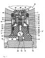
- the piston pump according to the invention with the features of claim 1 has a piston which is designed as a hollow piston and whose interior forms a displacement chamber of the piston pump.
- the formation of the piston as a hollow piston and the possible possible displacement of the displacement chamber into the piston allows a considerable137de piston pump with a compact design.
- In an open side of the piston protrudes a fixed inner part, which limits the displacement chamber on one side of the piston.
- a dead volume of the displacement chamber so a minimum volume of the displacement chamber at the end of a delivery stroke, can be reduced to almost zero, whereby a high efficiency of the piston pump is achieved.
- the piston of the piston pump according to the invention is produced as a formed part by forming, for example by deep drawing, cold rolling or extrusion.
- the piston is, for example, tubular or sleeve-shaped with a closing on one side, integral with it piston end wall. He has, at least before the assembly with the inner part, no undercuts and is thus quickly and easily produced by forming in one operation. To increase the wear resistance of the piston may be cured, any other processing or reworking such as a fine machining of its surface is unnecessary.
- the piston is inexpensive and fast to produce.
- the piston is designed as a stepped piston, ie it is guided and sealed at two axially spaced locations on different diameters in a pump bore in a pump housing.
- the formation of the piston as a stepped piston results surrounding the piston annular space whose volume is alternately increased and decreased during the reciprocating stroke movement of the piston.
- the volume of the annular space increases, whereby fluid from the piston pump is sucked into the annular space.
- the volume of the annular space decreases, but the volume of the displacement chamber increases more as the volume of the annular space decreases, whereby the piston pump sucks fluid.
- the piston pump according to the invention therefore sucks both during the delivery and during the return stroke.
- the inner part has an undercut, which engages behind the piston.
- the piston and the inner part form a preassembly assembly; they are inextricably linked.
- Advantage of this embodiment of the invention is the ease of handling of the piston and the inner part comprehensive preassembly assembly to its installation in a pump housing. After installation of the pre-assembly in the pump housing, the securing of the piston on the inner part is no longer needed because the piston is secured by the eccentric on the inner part. On the quality and strength of the connection of the piston and the inner part therefore only small claims are made.
- a check valve (exhaust valve) is housed in the inner part, which controls a fluid flow direction of the fluid pumped by the piston pump through the piston pump.
- the check valve has a valve closing body, which is guided by a valve-closure member guide in a valve lifting direction. At least one fluid passage is provided, through which fluid can flow over the valve closing body when the check valve is open. Through the fluid passage, it is possible to closely tolerate the valve-closing body guide with respect to the valve-closing body.
- the tightly-tolerated valve-closing member guide has the advantage of reducing noise since it largely prevents side-to-side movement of the open valve-closing member lifted from a valve seat, which is excited by fluid flowing around the valve-closing member.
- An inlet valve 44 of the piston pump 10 is housed in the interior of the piston 16 forming the displacement chamber 42.
- the inlet valve 44 is formed as a spring-loaded check valve.
- the inlet valve 44 has a cup-shaped valve seat part 46, which is made as a plastic part and rests with a bottom inside the piston end wall 18.
- the piston return spring 40 presses the valve seat part 46 from the inside against the piston end wall 18 and thereby holds the valve seat part 46 in the piston 16.
- the valve seat portion 46 has a smaller diameter than an inner diameter of the piston 16, so that an annular space 48 between the valve seat portion 46 and the piston 16 is made.
- a sealing lip 50 closes the annulus 48 from.
- the sealing lip 50 separates the displacement chamber 42 from the annular space 48.
- the bottom of the valve seat part 46 is penetrated by a central hole 52, the mouth of which is designed as a conical valve seat 54 of the inlet valve 44.
- Radial grooves 56 mounted in the shape of a star in the bottom of the valve seat part 46 connect the annular space 48 to the center hole 52.
- the inlet valve 44 has a valve ball 58, which is pressed by a helical compression spring as a valve closing spring 60 against the valve seat 54.
- the valve closing spring 60 is supported on the pin-shaped projection 22 of the protruding into the piston 16 inner part 24.
- the fluid inlet into the piston pump 10 takes place through an inlet bore 62, which is mounted in the pump housing 14 and opens radially into the pump bore 12. Fluid flows from the pump bore 12 through passage openings 64 punched out of a circumferential wall of the piston 16 into the annular space 48 between the valve seat part 46 and the peripheral wall of the piston 16 and thence through the radial passages 56 and the center hole 52 to the inlet valve 44.
- An outlet valve 66 of the piston pump 10 is housed in an axially continuous central hole 68 in the inner part 24.
- the center hole 68 widens conically to form a valve seat 70.
- a helical compression spring as a valve closing spring 72 presses a valve ball 74 as a valve closing body against the valve seat 70th
- the valve closing spring 72 is supported on a circular closure disc 76 which is inserted into the pump bore 12.
- the closure disc 76 is held with a peripheral caulking 78 of the pump housing 14 in the pump bore 12 and closes the pump bore 12 pressure-tight.
- the closure disc 76 in turn holds the inner part 24 at the base plate 26 fixed in the pump bore 12th
- the center hole 68 in the inner part 24 axially parallel arranged guide ribs 84, which are formed in the manner of an inner knurl or a Dahlnutprofils.
- the guide ribs 84 guide the valve ball 74 with narrow radial tolerance in the valve lift direction, d. H. in the axial direction. Passage grooves exist between the guide ribs 84 which, taken together, have a large area for passage of fluid exiting through the outlet valve 66.
Landscapes
- Engineering & Computer Science (AREA)
- Mechanical Engineering (AREA)
- General Engineering & Computer Science (AREA)
- Physics & Mathematics (AREA)
- Fluid Mechanics (AREA)
- Transportation (AREA)
- Details Of Reciprocating Pumps (AREA)
Claims (6)
- Pompe à piston (10) comportant un piston (16) pouvant être entraîné dans un mouvement linéaire de va-et-vient, dans laquelle le piston (16) a la conception d'un piston creux dont l'intérieur forme une chambre de refoulement (42) de la pompe à piston (10) et la pompe à piston (10) présente une partie intérieure fixe (24) qui fait saillie dans une partie ouverte du piston (16),
caractérisée en ce que
le piston (16) est une pièce ayant subi une mise en forme plastique et, à l'intérieur du piston (16), une partie de siège de soupape (46) sépare un espace annulaire (48), existant entre la partie de siège de soupape (46) et la paroi intérieure du piston (16), de la chambre de refoulement (42), et forme le siège (54) d'une soupape d'admission (44) qui régule la relation fluidique entre l'espace annulaire (48) et la chambre de refoulement (42). - Pompe à piston selon la revendication 1,
caractérisée en ce que
le piston (16) a la conception d'un piston étagé. - Pompe à piston selon la revendication 1,
caractérisée en ce que
le piston (16) s'engage derrière une contre-dépouille (36) de la partie intérieure (24). - Pompe à piston selon la revendication 1,
caractérisée en ce qu'
un clapet anti-retour (66) régulant une direction d'écoulement de fluide à l'intérieur de la pompe à piston (10) est logé dans la partie intérieure (24). - Pompe à piston selon la revendication 4,
caractérisée en ce que
le clapet anti-retour (66) présente un obturateur de soupape (74) et un guide d'obturateur de soupape (84) qui guide l'obturateur de soupape (74) dans une direction de levée de soupape, le guide d'obturateur de soupape (84) présentant au moins un passage de fluide par lequel peut s'écouler le fluide au niveau de l'obturateur de soupape (74) lorsque le clapet anti-retour (66) est ouvert. - Pompe à piston selon la revendication 5,
caractérisée en ce que
le clapet anti-retour (66) présente des nervures de guidage (84) servant de guide pour l'obturateur de soupape (74), ces nervures de guidage (84) définissant entre elles des rainures de passage par lesquelles le fluide peut s'écouler au niveau de l'obturateur de soupape (74) lorsque le clapet anti-retour (66) est ouvert.
Applications Claiming Priority (3)
| Application Number | Priority Date | Filing Date | Title |
|---|---|---|---|
| DE19918127A DE19918127A1 (de) | 1999-04-22 | 1999-04-22 | Kolbenpumpe |
| DE19918127 | 1999-04-22 | ||
| PCT/DE2000/000396 WO2000064717A1 (fr) | 1999-04-22 | 2000-02-09 | Pompe a piston |
Publications (2)
| Publication Number | Publication Date |
|---|---|
| EP1089902A1 EP1089902A1 (fr) | 2001-04-11 |
| EP1089902B1 true EP1089902B1 (fr) | 2006-01-04 |
Family
ID=7905384
Family Applications (1)
| Application Number | Title | Priority Date | Filing Date |
|---|---|---|---|
| EP00909031A Expired - Lifetime EP1089902B1 (fr) | 1999-04-22 | 2000-02-09 | Pompe a piston |
Country Status (5)
| Country | Link |
|---|---|
| US (1) | US6514055B1 (fr) |
| EP (1) | EP1089902B1 (fr) |
| JP (1) | JP2002542430A (fr) |
| DE (2) | DE19918127A1 (fr) |
| WO (1) | WO2000064717A1 (fr) |
Families Citing this family (13)
| Publication number | Priority date | Publication date | Assignee | Title |
|---|---|---|---|---|
| DE10117600C1 (de) * | 2001-04-07 | 2002-08-22 | Bosch Gmbh Robert | Hochdruck-Kraftstoffpumpe für ein Kraftstoffsystem einer direkteinspritzenden Brennkraftmaschine, Kraftstoffsystem sowie Brennkraftmaschine |
| DE102004060080B4 (de) * | 2004-07-08 | 2015-02-05 | Continental Teves Ag & Co. Ohg | Kraftfahrzeug-Bremsanlage |
| DE102004052817A1 (de) * | 2004-11-02 | 2006-05-04 | Robert Bosch Gmbh | Kolbenpumpe |
| US20090057345A1 (en) * | 2007-08-31 | 2009-03-05 | Dukes Stephen A | Fluid dispenser |
| DE102007047417B4 (de) * | 2007-10-04 | 2026-03-05 | Robert Bosch Gmbh | Kolbenpumpe zur Förderung eines Fluids und zugehöriges Bremssystem |
| DE102007054097A1 (de) | 2007-11-13 | 2009-05-14 | Robert Bosch Gmbh | Pumpenelement, Hydraulikblock mit Pumpenelement sowie Montageverfahren |
| USD592899S1 (en) | 2008-04-25 | 2009-05-26 | Impact Products Llc | Soap dispenser |
| JP5498412B2 (ja) * | 2011-02-24 | 2014-05-21 | 日信工業株式会社 | プランジャポンプの製造方法およびプランジャポンプ |
| EP3034057B1 (fr) * | 2014-12-19 | 2019-01-30 | Stryker Corporation | Appareil de support pour patient avec système de commande hydraulique |
| JP6733991B2 (ja) * | 2016-09-23 | 2020-08-05 | 日立オートモティブシステムズ株式会社 | プランジャポンプ及びブレーキ装置 |
| US10544878B2 (en) * | 2017-11-14 | 2020-01-28 | Forum Us, Inc. | Flow control assembly for subsea applications |
| US12497954B2 (en) * | 2023-01-23 | 2025-12-16 | Dana Italia S.R.L. | Compact volumetric pump |
| US20250257723A1 (en) * | 2024-02-12 | 2025-08-14 | Dana Italia S.R.L. | Valveless, mechanical, pressure regulating pump |
Family Cites Families (10)
| Publication number | Priority date | Publication date | Assignee | Title |
|---|---|---|---|---|
| FR957606A (fr) * | 1950-02-23 | |||
| US2444159A (en) * | 1944-09-20 | 1948-06-29 | Gisholt Machine Co | Fluid pump |
| US2433812A (en) * | 1944-11-04 | 1947-12-30 | Shepard Co Lewis | Power-driven cylinder piston pump |
| US2981198A (en) * | 1958-08-12 | 1961-04-25 | Nettel Frederick | Reciprocating variable delivery pump |
| US3263622A (en) * | 1964-06-01 | 1966-08-02 | Jr Lewis Tyree | Pump |
| DE3133111A1 (de) * | 1981-08-21 | 1983-04-14 | Robert Bosch Gmbh, 7000 Stuttgart | Druckbeschaffungseinrichtung |
| DE3147240A1 (de) * | 1981-11-28 | 1983-06-09 | Mannesmann Rexroth GmbH, 8770 Lohr | Radialkolbenmaschine |
| DE4107979C2 (de) | 1991-03-13 | 1998-07-09 | Bosch Gmbh Robert | Hydraulische Hochdruckpumpe für Kraftfahrzeug-Bremsanlagen |
| DE19739904A1 (de) * | 1997-09-11 | 1999-03-18 | Bosch Gmbh Robert | Rückschlagventil, insbesondere für eine Kolbenpumpe |
| DE19747672A1 (de) * | 1997-10-29 | 1999-05-06 | Bosch Gmbh Robert | Kolbenpumpe |
-
1999
- 1999-04-22 DE DE19918127A patent/DE19918127A1/de not_active Withdrawn
-
2000
- 2000-02-09 US US09/719,684 patent/US6514055B1/en not_active Expired - Fee Related
- 2000-02-09 EP EP00909031A patent/EP1089902B1/fr not_active Expired - Lifetime
- 2000-02-09 WO PCT/DE2000/000396 patent/WO2000064717A1/fr not_active Ceased
- 2000-02-09 JP JP2000613684A patent/JP2002542430A/ja active Pending
- 2000-02-09 DE DE50012016T patent/DE50012016D1/de not_active Expired - Lifetime
Also Published As
| Publication number | Publication date |
|---|---|
| JP2002542430A (ja) | 2002-12-10 |
| US6514055B1 (en) | 2003-02-04 |
| EP1089902A1 (fr) | 2001-04-11 |
| WO2000064717A1 (fr) | 2000-11-02 |
| DE19918127A1 (de) | 2000-10-26 |
| DE50012016D1 (de) | 2006-03-30 |
Similar Documents
| Publication | Publication Date | Title |
|---|---|---|
| EP1101035B1 (fr) | Pompe a piston | |
| EP0932761B1 (fr) | Pompe a piston | |
| DE19752545B4 (de) | Kolbenpumpe | |
| DE19803333A1 (de) | Kolbenpumpe | |
| DE19928913A1 (de) | Kolbenpumpe | |
| EP0935719B1 (fr) | Clapet anti-retour destine notamment a une pompe a piston | |
| EP0928894A2 (fr) | Piston en matériau plastique d' une pompe à piston pour un système de freinage hydraulique dans un véhicule | |
| EP0932762A1 (fr) | Piston tubulaire produit par formage a froid et bouchon de fermeture pour une pompe a pistons radiaux | |
| DE19747672A1 (de) | Kolbenpumpe | |
| DE19732791A1 (de) | Kolbenpumpe | |
| EP1090228B1 (fr) | Pompe a piston | |
| EP1282776B1 (fr) | Clapet antiretour pour pompe a piston | |
| EP1089902A1 (fr) | Pompe a piston | |
| EP1090230B1 (fr) | Pompe a piston | |
| EP1082544A1 (fr) | Pompe a piston | |
| DE19732747B4 (de) | Rückschlagventil | |
| DE19809592B4 (de) | Kolbenpumpe | |
| DE10049909A1 (de) | Kolbenpumpe | |
| DE19918121B4 (de) | Kolbenpumpe | |
| EP1362187A1 (fr) | Pompe a piston | |
| DE19918126A1 (de) | Kolbenpumpe | |
| DE19847471B4 (de) | Kolbenpumpe | |
| DE19812043B4 (de) | Kolbenpumpe | |
| DE19732748A1 (de) | Kolbenpumpe | |
| DE19833840A1 (de) | Kolbenpumpe |
Legal Events
| Date | Code | Title | Description |
|---|---|---|---|
| PUAI | Public reference made under article 153(3) epc to a published international application that has entered the european phase |
Free format text: ORIGINAL CODE: 0009012 |
|
| AK | Designated contracting states |
Kind code of ref document: A1 Designated state(s): AT BE CH CY DE DK ES FI FR GB GR IE IT LI LU MC NL PT SE |
|
| 17P | Request for examination filed |
Effective date: 20010502 |
|
| RBV | Designated contracting states (corrected) |
Designated state(s): DE FR GB IT |
|
| 17Q | First examination report despatched |
Effective date: 20050208 |
|
| GRAP | Despatch of communication of intention to grant a patent |
Free format text: ORIGINAL CODE: EPIDOSNIGR1 |
|
| GRAS | Grant fee paid |
Free format text: ORIGINAL CODE: EPIDOSNIGR3 |
|
| GRAA | (expected) grant |
Free format text: ORIGINAL CODE: 0009210 |
|
| AK | Designated contracting states |
Kind code of ref document: B1 Designated state(s): DE FR GB IT |
|
| PG25 | Lapsed in a contracting state [announced via postgrant information from national office to epo] |
Ref country code: IT Free format text: LAPSE BECAUSE OF FAILURE TO SUBMIT A TRANSLATION OF THE DESCRIPTION OR TO PAY THE FEE WITHIN THE PRESCRIBED TIME-LIMIT;WARNING: LAPSES OF ITALIAN PATENTS WITH EFFECTIVE DATE BEFORE 2007 MAY HAVE OCCURRED AT ANY TIME BEFORE 2007. THE CORRECT EFFECTIVE DATE MAY BE DIFFERENT FROM THE ONE RECORDED. Effective date: 20060104 |
|
| REG | Reference to a national code |
Ref country code: GB Ref legal event code: FG4D Free format text: NOT ENGLISH |
|
| REF | Corresponds to: |
Ref document number: 50012016 Country of ref document: DE Date of ref document: 20060330 Kind code of ref document: P |
|
| GBT | Gb: translation of ep patent filed (gb section 77(6)(a)/1977) |
Effective date: 20060410 |
|
| ET | Fr: translation filed | ||
| PLBE | No opposition filed within time limit |
Free format text: ORIGINAL CODE: 0009261 |
|
| STAA | Information on the status of an ep patent application or granted ep patent |
Free format text: STATUS: NO OPPOSITION FILED WITHIN TIME LIMIT |
|
| 26N | No opposition filed |
Effective date: 20061005 |
|
| PGFP | Annual fee paid to national office [announced via postgrant information from national office to epo] |
Ref country code: FR Payment date: 20130315 Year of fee payment: 14 Ref country code: GB Payment date: 20130219 Year of fee payment: 14 |
|
| GBPC | Gb: european patent ceased through non-payment of renewal fee |
Effective date: 20140209 |
|
| REG | Reference to a national code |
Ref country code: FR Ref legal event code: ST Effective date: 20141031 |
|
| PG25 | Lapsed in a contracting state [announced via postgrant information from national office to epo] |
Ref country code: GB Free format text: LAPSE BECAUSE OF NON-PAYMENT OF DUE FEES Effective date: 20140209 Ref country code: FR Free format text: LAPSE BECAUSE OF NON-PAYMENT OF DUE FEES Effective date: 20140228 |
|
| PGFP | Annual fee paid to national office [announced via postgrant information from national office to epo] |
Ref country code: DE Payment date: 20160426 Year of fee payment: 17 |
|
| REG | Reference to a national code |
Ref country code: DE Ref legal event code: R119 Ref document number: 50012016 Country of ref document: DE |
|
| PG25 | Lapsed in a contracting state [announced via postgrant information from national office to epo] |
Ref country code: DE Free format text: LAPSE BECAUSE OF NON-PAYMENT OF DUE FEES Effective date: 20170901 |