EP1089915B1 - Dispositif à valve et moyens de perçage pour sac souple placé dans un conteneur - Google Patents
Dispositif à valve et moyens de perçage pour sac souple placé dans un conteneur Download PDFInfo
- Publication number
- EP1089915B1 EP1089915B1 EP99908675A EP99908675A EP1089915B1 EP 1089915 B1 EP1089915 B1 EP 1089915B1 EP 99908675 A EP99908675 A EP 99908675A EP 99908675 A EP99908675 A EP 99908675A EP 1089915 B1 EP1089915 B1 EP 1089915B1
- Authority
- EP
- European Patent Office
- Prior art keywords
- bore
- valve
- valve assembly
- closure member
- crank pin
- Prior art date
- Legal status (The legal status is an assumption and is not a legal conclusion. Google has not performed a legal analysis and makes no representation as to the accuracy of the status listed.)
- Expired - Lifetime
Links
- 238000007789 sealing Methods 0.000 claims description 27
- 239000007788 liquid Substances 0.000 claims description 20
- 239000012528 membrane Substances 0.000 claims description 20
- 230000007704 transition Effects 0.000 claims description 6
- 239000012530 fluid Substances 0.000 claims 1
- 239000000463 material Substances 0.000 description 5
- 239000004820 Pressure-sensitive adhesive Substances 0.000 description 2
- 230000008901 benefit Effects 0.000 description 2
- 238000004891 communication Methods 0.000 description 2
- 238000001514 detection method Methods 0.000 description 2
- 238000007599 discharging Methods 0.000 description 2
- 230000005484 gravity Effects 0.000 description 2
- 238000010348 incorporation Methods 0.000 description 2
- 238000003466 welding Methods 0.000 description 2
- 230000000712 assembly Effects 0.000 description 1
- 238000000429 assembly Methods 0.000 description 1
- 230000008859 change Effects 0.000 description 1
- 238000011109 contamination Methods 0.000 description 1
- 230000008878 coupling Effects 0.000 description 1
- 238000010168 coupling process Methods 0.000 description 1
- 238000005859 coupling reaction Methods 0.000 description 1
- 230000002452 interceptive effect Effects 0.000 description 1
- 238000000034 method Methods 0.000 description 1
- 230000004048 modification Effects 0.000 description 1
- 238000012986 modification Methods 0.000 description 1
- 239000004033 plastic Substances 0.000 description 1
- 239000002985 plastic film Substances 0.000 description 1
- 229920006255 plastic film Polymers 0.000 description 1
- 239000007787 solid Substances 0.000 description 1
- 238000011144 upstream manufacturing Methods 0.000 description 1
- XLYOFNOQVPJJNP-UHFFFAOYSA-N water Substances O XLYOFNOQVPJJNP-UHFFFAOYSA-N 0.000 description 1
Images


Classifications
-
- F—MECHANICAL ENGINEERING; LIGHTING; HEATING; WEAPONS; BLASTING
- F16—ENGINEERING ELEMENTS AND UNITS; GENERAL MEASURES FOR PRODUCING AND MAINTAINING EFFECTIVE FUNCTIONING OF MACHINES OR INSTALLATIONS; THERMAL INSULATION IN GENERAL
- F16K—VALVES; TAPS; COCKS; ACTUATING-FLOATS; DEVICES FOR VENTING OR AERATING
- F16K51/00—Other details not peculiar to particular types of valves or cut-off apparatus
-
- B—PERFORMING OPERATIONS; TRANSPORTING
- B65—CONVEYING; PACKING; STORING; HANDLING THIN OR FILAMENTARY MATERIAL
- B65D—CONTAINERS FOR STORAGE OR TRANSPORT OF ARTICLES OR MATERIALS, e.g. BAGS, BARRELS, BOTTLES, BOXES, CANS, CARTONS, CRATES, DRUMS, JARS, TANKS, HOPPERS, FORWARDING CONTAINERS; ACCESSORIES, CLOSURES, OR FITTINGS THEREFOR; PACKAGING ELEMENTS; PACKAGES
- B65D77/00—Packages formed by enclosing articles or materials in preformed containers, e.g. boxes, cartons, sacks or bags
- B65D77/04—Articles or materials enclosed in two or more containers disposed one within another
- B65D77/06—Liquids or semi-liquids or other materials or articles enclosed in flexible containers disposed within rigid containers
- B65D77/062—Flexible containers disposed within polygonal containers formed by folding a carton blank
- B65D77/065—Spouts, pouring necks or discharging tubes fixed to or integral with the flexible container
- B65D77/067—Spouts, pouring necks or discharging tubes fixed to or integral with the flexible container combined with a valve, a tap or a piercer
-
- B—PERFORMING OPERATIONS; TRANSPORTING
- B67—OPENING, CLOSING OR CLEANING BOTTLES, JARS OR SIMILAR CONTAINERS; LIQUID HANDLING
- B67B—APPLYING CLOSURE MEMBERS TO BOTTLES JARS, OR SIMILAR CONTAINERS; OPENING CLOSED CONTAINERS
- B67B7/00—Hand- or power-operated devices for opening closed containers
- B67B7/24—Hole-piercing devices
- B67B7/26—Hole-piercing devices combined with spouts
-
- F—MECHANICAL ENGINEERING; LIGHTING; HEATING; WEAPONS; BLASTING
- F16—ENGINEERING ELEMENTS AND UNITS; GENERAL MEASURES FOR PRODUCING AND MAINTAINING EFFECTIVE FUNCTIONING OF MACHINES OR INSTALLATIONS; THERMAL INSULATION IN GENERAL
- F16K—VALVES; TAPS; COCKS; ACTUATING-FLOATS; DEVICES FOR VENTING OR AERATING
- F16K13/00—Other constructional types of cut-off apparatus; Arrangements for cutting-off
- F16K13/04—Other constructional types of cut-off apparatus; Arrangements for cutting-off with a breakable closure member
-
- F—MECHANICAL ENGINEERING; LIGHTING; HEATING; WEAPONS; BLASTING
- F16—ENGINEERING ELEMENTS AND UNITS; GENERAL MEASURES FOR PRODUCING AND MAINTAINING EFFECTIVE FUNCTIONING OF MACHINES OR INSTALLATIONS; THERMAL INSULATION IN GENERAL
- F16K—VALVES; TAPS; COCKS; ACTUATING-FLOATS; DEVICES FOR VENTING OR AERATING
- F16K31/00—Actuating devices; Operating means; Releasing devices
- F16K31/44—Mechanical actuating means
- F16K31/52—Mechanical actuating means with crank, eccentric, or cam
- F16K31/528—Mechanical actuating means with crank, eccentric, or cam with pin and slot
Definitions
- This invention relates to valves for use with or for incorporation with liner bags as used in containers to house liquids.
- liquids is to be understood to mean materials which have a viscosity, either inherent or induced by heat or other means, which allows the material to flow under the influence of gravity.
- lard a material, such as lard, which is solid in its natural condition at room temperature, but when heated can flow and gravity discharge from a container.
- containers which include a base (conventionally adapted to act as a pallet with means to allow the use of a fork lift truck or a hand truck), four sides coupled to the base and a lid.
- a plastic film liner bag is located in the container to house the liquid. Discharge of the liquid is achieved through a nozzle mounted on the bag and accessible from outside the container.
- the liner bag nozzle is in direct communication with the interior of the liner bag.
- the nozzle extends down into the base and then outwardly towards a side of the base.
- the nozzle at its outlet end is threaded allowing a delivery hose to be coupled to the nozzle after the removal of a sealing cap, normally resident on the thread.
- the cap protects the nozzle thread against damage and prevents contamination entering the nozzle.
- the cap also serves a third and most important double security purpose. It ensures that any leakage through the butterfly valve when closed is contained in the nozzle and the cap usually has an associated tamper detection means.
- the liner bag and its butterfly valved nozzle is a one-use only item.
- a bottom discharge liner bag with an integral nozzle with valve is far more expensive than a liner bag with a nozzle for side discharge, another strategy in use for discharging liquid from containers.
- the nozzle has no valve.
- the nozzle is threaded at its outlet end for a cap. Because the nozzle bore is not in direct communication with the interior of the liner bag, being separated from the liner bag contents by a membrane over the inlet end of the bore of the nozzle, the cap does not need to be a sealing cap or include a tamper detection means.
- a one-use liner bag for side discharge is thus considerably cheaper than the one-use liner bag for a bottom discharge system. Cost is an important factor when the liner bag is used only once and then discarded.
- the capped nozzle discharge end projects from a side of the container.
- the cap In a discharge operation, the cap is removed and a membrane rupturing device is inserted into the nozzle.
- the rupturing device is forced against the membrane as a reusable valve is threaded onto the nozzle. It follows that as soon as the membrane is ruptured the liner bag contents will enter the nozzle but discharge from the nozzle is prevented by the coupled reusable valve until discharge of the liner bag contents is required.
- the bottom discharge system has the advantage that the valve is part of the bag nozzle and is discarded with the bag, but the disadvantage that the membrane concept of the side discharge system cannot be utilised with known nozzle/valve assemblies.
- the present invention has been devised to provide a valve assembly for use with or incorporation with container liner bags, where the valve means acts as a discharge nozzle and is a self contained inexpensive disposable unit which incorporates a membrane puncturing arrangement.
- the invention provides a valve of the general type disclosed in US patent A-4 440 316 which enables the liquid in a sealed liner bag in a container to be readily discharged.
- the present invention shares some charateristics of the valve of the above patent, namely, a body with a bore in which is housed a slidable closure member having liner bag puncturing means, sealing means on the closure member and in the body bore are engagable to isolate the inlet of the body bore from the outlet of the body bore, and manually operable means is provided to move the closure member between positions where the sealing means is engaged and is disengaged to cause puncturing of the liner bag and permit liquid flow through the body bore.
- the present invention is defined in the appended claims.
- the valve assembly 1 illustrated has a body 2 with a through bore 33 which includes a transition portion separating a first circular cross-section bore part 4, extending between the transition portion and a bore discharge end, from a larger diameter circular cross-section bore part 5, extending from the transition portion to a bore inlet end.
- the bore transition portion has an annular sealing face 6 facing towards the bore inlet end and lying in a plane inclined to the axis of the bore.
- the valve body 2 has a flange 7 whereby the valve body can be welded to the wall of a liner bag in one of several ways, as will be described later.
- the closure member 8 includes a head part 9, which in end view is circular, and a stem 34 directed away from the head 9 towards the bore discharge end.
- the closure member head 9 has an annular rear face 10 which lies adjacent the stem and is in a plane at substantially the same angle to the axis of the closure member as is the face 6. As the face 10 is substantially parallel to the face 6 sealing contact between the faces 6 and 10 isolates the inlet end of the body bore from the discharge end of the body bore.
- the closure member head part 9, upstream from the sealing face 10, is provided with an upstanding thin annular ring on its end and there are teeth 11 along at least the major part of the annular ring.
- the stem 34 of the closure member extends away from the head part 9 as four vanes 12 radiating from a central stem spine 31 with the radial tips of the vanes 12 lying on the circumference of a notional circle with a diameter slightly less than the diameter of the bore part 4.
- the vane tips act as bearing surfaces engagable with the bore part 4 to provide guidance and support for the member 8 as it slides in the bore of the body 2.
- the configuration of the closure member 8 can be best seen in Figs. 3 - 6.
- the closure member 8 is moved along the bore of the body 2 by a cranked member 13 comprising a pair of shafts 14,15 respectively pivotally mounted in a blind hole 16 in the wall of the body 2 and in a bearing 17 mounted in the wall of the body 2.
- the shafts 14,15 share a common axis which lies diametrically across the body bore part 4.
- the shafts 14 and 15 are connected to a crank pin 20 by two crank arms 18,19.
- the crank pin 20 is housed in a lateral and axially offset slot 21 in the closure member 8 which extends from the spine 31 through parts of two of the vanes 12.
- the length of the crank arms 18,19 is such that by rotating the cranked member 13 about the common axis of the shafts 14,15, as by a handle or the like on the portion of the shaft 15 extending from the body 2, the crank pin 20 will bear against a side of the slot 21 to move the closure member 8 relative to the valve body 2.
- Rotation of the shafts 14,15 through 180 degrees will move the closure member 8 from the Fig.1 condition to the Fig.2 condition.
- the faces 6,10 are in sealing engagement.
- the faces 6,10 are separated and the head of the closure member lies outside the body bore allowing free passage of liquid into the bore of the body around the head 9 of the closure member 8 to pass between the vanes 12 to the bore discharge end.
- Fig.3 is a side view of the closure member 8.
- Fig.4 is an end view in the direction of the arrow 4 in Fig.3.
- Fig.5 is an end view in the direction of the arrow 5 in Fig.3.
- Fig.6 is side view in the direction of the arrow 6 in Fig.3.
- the slot 21 has a width slightly larger than the diameter of the crank pin 20 thereby allowing sliding of the crank pin 20 in the slot 21 with a small working clearance. It will be seen from Figs.3 to 6 that the slots 21 in the vanes 12 have a common inner end 22 which extends into the spine 31 of the closure member 8. The shaded portion in Fig.3 indicates the common end 22 of the slots 21 cut into the spine of the stem.
- the crank pin 20 at the two ends of its arcuate travel to move the closure member 8 in the body bore will have its axis intersecting the central axis of the spine 31 of the stem of the closure member 8.
- Fig.6 two small projections 23 are shown extending into the slots 21 and are preferred features.
- the projections 23 narrow the width of the slots 21 and in theory prevent the crank pin 20 entering the end 22 of the slots.
- the closure member 8 is made from a resilient plastic material the crank pin 20 can be forced (with resilient deflection of some or all of the projections, the vanes and the walls of the slot) into the end 22 of the slots where it is latched by the projections 23 until forcibly removed by rotation of the crank member 13. It would be possible to achieve the above result using only one projection 23.
- latching arrangement as just described hold the faces 6, 10 in sealed condition when the closure member is in the Fig.1 condition and also holds the closure member in the extended condition of Fig.2.
- latching means can be used, for example, a detent arrangement on the shaft 15 where it extends from the bearing 17. Whilst the latching arrangements proposed are desirable their function could be substantially duplicated by having (at least) the shaft 15 as a tight frictional fit in the bore of the bush 17.
- the nozzle-valve as just described is welded to a liner bag for a container.
- a hole is made in the liner bag indicated 32 in Fig.1, and the liner bag 32 is welded around that hole to the flange 7 of the body 2 with the body extension 24 projecting through the hole in the liner bag 32 into the interior of the liner bag.
- a delivery hose Prior to piercing the membrane a delivery hose would be coupled to the threaded end 27 of the body 2.
- some means such as a spike or pressure sensitive adhesive, would be associated with the head 9 of the closure member 8 to hold a severed membrane disk 26 captive.
- the membrane portion severed will be in the form a flap.
- a spike or a pressure sensitive adhesive or some other suitable means would be provided to prevent the flap interfering with the discharge of the liquid and the operation of the closure member.
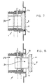
- Fig.7 there is an O ring 29 or like continuous sealing ring member mounted in the body bore portion 5 and it engages the outer surface of the head 9 of the closure member 8.
- This form of seal could be used to replace the sealing achieved by the engagement of the faces 6,10 or to back-up that sealing engagement. If used as a back-up seal it would be possible to eliminate the membrane 25 and the teeth 11 on the closure member 8.
- the membrane method of positively separating the liquid contents of a liner bag from the nozzle/valve for discharging the liquid to be the most effective means of retaining liquid in a liner bag during storage and transport of the liquid.
- a sealing ring 28 mounted in the bore face 6 and the crank member 13 when operated would draw the closure member face 10 into compressing and sealing contact with the sealing ring 28.
- the sealing ring 28 could be mounted on the face 10 of the closure member 8 and engage with the bore face 6.
- the double ended crank member 13 could be made with a robust shaft 15 and bearing 17, and the crank pin 20 could be supported by a single crank arm 18.
- vanes 12 as illustrated are axial and radial, it would be possible to make the vanes in other forms. For example, spiral or radial with slots or holes in the vanes to allow liquid flow along the closure member stem, whilst still having the required guidance and support of the closure member vanes from the bore part 4.
- valve body as illustrated is externally threaded.
- bore part 4 could be internally threaded or means other than threads could be provided to allow coupling of a liquid delivery pipe to the valve body.
Landscapes
- Engineering & Computer Science (AREA)
- General Engineering & Computer Science (AREA)
- Mechanical Engineering (AREA)
- Closures For Containers (AREA)
- Bag Frames (AREA)
- Mechanically-Actuated Valves (AREA)
Claims (10)
- Dispositif à valve (1) comprenant un corps muni d'un alésage transversal (33) ayant une extrémité d'entrée et une extrémité de sortie, une bride (7) sur le corps (2) autour de l'extrémité d'entrée de l'alésage moyennant quoi les moyens formant valve (1) peuvent être fixés à la paroi d'un sac interne (32) pour un conteneur, une zone de transition d'interruption d'alésage dans l'alésage (33) séparant une première partie d'alésage (5) et une seconde partie d'alésage (4), un élément de fermeture allongé (8) comprenant une tige (34) munie d'une tête (9) séparée par une face de scellement (10) est monté dans ledit alésage de corps (33), des aubes dirigées radialement vers l'extérieur (12) de la tige (34) présentent des arêtes externes pour mettre en prise la seconde partie d'alésage (4) afin de supporter ainsi de manière coulissante ledit élément de fermeture (8) et des espaces entre lesdites aubes radiales (12) fournissent des chemins d'écoulement de fluide, ledit élément de fermeture (8) est mobile axialement entre un état fermé de la valve dans lequel il se produit une mise en prise étanche entre ladite face de scellement (10) et une surface de scellement (6) dans la zone de transition de l'alésage de corps (33) pour isoler l'extrémité d'entrée d'alésage de l'extrémité de sortie d'alésage et un état ouvert de la valve dans lequel ladite face de scellement (10) et ladite surface de scellement (6) sont séparées, des moyens de perforation de membrane (11) sur la tête de l'élément de fermeture (9), lesdits moyens de fermeture (11) étant situés à l'intérieur dudit alésage de corps lorsque ladite valve se trouve à l'état fermé et s'étendant au-delà de l'extrémité d'entrée de l'alésage de corps lorsque ladite valve se trouve à l'état ouvert, et des moyens pouvant être actionnés manuellement (13) pour déplacer axialement ledit élément de fermeture (8), caractérisé en ce que les moyens pouvant être actionnés manuellement (13) comprennent des moyens formant tourillon (14, 15) supportés de manière pivotante (16, 17) dans ledit corps de dispositif à valve (2) et un maneton de vilebrequin (20) connecté auxdits moyens formant tourillon (14, 15) et décalé de l'axe de mouvement de pivot desdits moyens formant tourillon (14, 15), ledit maneton de vilebrequin (20) est mis en prise dans des fentes radiales (21) dans des aubes sélectionnées desdites aubes (12) et la mise en prise dudit maneton de vilebrequin (20) avec des côtés desdites fentes radiales (21) à mesure que lesdits moyens formant tourillon (14, 15) sont mis partiellement en rotation déplace ledit élément de fermeture (8).
- Dispositif à valve (1) selon la revendication 1, dans lequel ladite tige (34) comprend une pointe centrale (31) à partir de laquelle lesdites aubes (12) rayonnent et qui présente un axe sensiblement coïncidant avec l'axe de l'alésage de corps (33) et est entrecoupé par l'axe de mouvement de pivot desdits moyens formant tourillon (14, 15), ledit maneton de vilebrequin (20) est mis en prise dans des fentes radiales (21) dans deux desdites aubes (12), lesdites fentes (21) se rencontrant et ayant une extrémité intérieure commune (22) coupée dans ladite pointe (31) et des extrémités extérieures (Y) divisent lesdites aubes (12).
- Dispositif à valve (1) selon la revendication 2, comprenant des moyens pour retenir de manière libérable ledit maneton de vilebrequin (20) au niveau de l'extrémité intérieure (22) desdites fentes (21).
- Dispositif à valve (1) selon la revendication 3, dans lequel les moyens pour retenir de manière libérable le maneton à vilebrequin (20) au niveau de l'extrémité intérieure (22) des fentes (21) comprend des moyens de restriction de largeur de fente (23) qui sont adjacents à ladite extrémité intérieure (22) des fentes (21) et ledit maneton à vilebrequin (20) peut être contraint de passer au-delà des moyens de restriction de largeur (23) pour positionner ledit maneton de vilebrequin (20) dans ou retirer celui-ci d'une position au niveau de l'extrémité intérieure (22) desdites fentes (21).
- Dispositif à valve (1) selon l'une quelconque des revendications 1 à 4 ayant un élément de scellement élastique (28) qui est disposé entre la surface de scellement d'alésage (6) et la face de scellement de l'élément de fermeture (10) et est comprimé lorsque la valve se trouve à l'état fermé.
- Dispositif à valve (1) selon la revendication 5, dans lequel l'élément de scellement élastique (28) a la forme d'un joint torique .
- Dispositif à valve (1) selon l'une quelconque des revendications 1 à 4, ayant un élément de scellement élastique en forme de joint torique (29) entre des faces de la tête de l'élément de fermeture (9) et la première partie d'alésage (5) qui sont en relation de recouvrement concentrique lorsque la valve est à l'état fermé.
- Dispositif à valve (1) selon l'une quelconque des revendications 1 à 7, dans lequel lesdits moyens de perforation (11) comprennent un ensemble de dents s'étendant axialement sur la tête de l'élément de fermeture (9) qui est adapté à la perforation et au sectionnement au moins partiel d'un capot d'une membrane (32) s'étendant sur l'extrémité intérieure dudit alésage de corps.
- Dispositif à valve (1) selon l'une quelconque des revendications 1 à 8 comprenant une membrane pouvant être perforée fixée audit corps de valve (2) et recouvrant et scellant l'extrémité d'entrée de l'alésage du corps (33).
- Dispositif à valve (1) selon l'une quelconque des revendications précédentes, dans lequel le corps de valve adjacent à l'extrémité de sortie de l'alésage de corps est adapté (27) pour être mis en prise de manière filetée par des moyens de distribution de liquide pour délivrer du liquide depuis le dispositif à valve (1) vers une destination souhaitée.
Applications Claiming Priority (3)
| Application Number | Priority Date | Filing Date | Title |
|---|---|---|---|
| AUPP2741A AUPP274198A0 (en) | 1998-04-01 | 1998-04-01 | Nozzle-valve arrangement for liner bags for containers |
| AUPP274198 | 1998-04-01 | ||
| PCT/AU1999/000115 WO1999051504A1 (fr) | 1998-04-01 | 1999-03-02 | Sacs-doublage de contenants pourvus de moyens de perforation/piquage |
Publications (3)
| Publication Number | Publication Date |
|---|---|
| EP1089915A1 EP1089915A1 (fr) | 2001-04-11 |
| EP1089915A4 EP1089915A4 (fr) | 2001-05-30 |
| EP1089915B1 true EP1089915B1 (fr) | 2003-02-19 |
Family
ID=3807002
Family Applications (1)
| Application Number | Title | Priority Date | Filing Date |
|---|---|---|---|
| EP99908675A Expired - Lifetime EP1089915B1 (fr) | 1998-04-01 | 1999-03-02 | Dispositif à valve et moyens de perçage pour sac souple placé dans un conteneur |
Country Status (7)
| Country | Link |
|---|---|
| US (1) | US6354466B1 (fr) |
| EP (1) | EP1089915B1 (fr) |
| CN (1) | CN1131818C (fr) |
| AU (1) | AUPP274198A0 (fr) |
| DE (1) | DE69905466T2 (fr) |
| NZ (1) | NZ507295A (fr) |
| WO (1) | WO1999051504A1 (fr) |
Families Citing this family (25)
| Publication number | Priority date | Publication date | Assignee | Title |
|---|---|---|---|---|
| GB0001779D0 (en) * | 2000-01-27 | 2000-03-22 | Pro Pack International Limited | Closure for containers |
| GB0120726D0 (en) * | 2001-08-25 | 2001-10-17 | Arena Ibc Ltd | Valve assembly for containers |
| ES2355615T3 (es) * | 2002-04-26 | 2011-03-29 | Millipore Corporation | Dispositivo de transferencia de fluido estéril desechable. |
| US7350535B2 (en) * | 2002-04-26 | 2008-04-01 | Gl Tool And Manufacturing Co. Inc. | Valve |
| ATE418032T1 (de) * | 2003-08-01 | 2009-01-15 | Gl Tool And Mfg Co Inc | Ventil |
| US7293477B2 (en) | 2003-12-23 | 2007-11-13 | Millipore Corporation | Disposable, pre-sterilized fluid receptacle sampling device |
| ATE481584T1 (de) * | 2004-07-30 | 2010-10-15 | Gl Tool And Mfg Co Inc | Ventil |
| WO2006022816A2 (fr) * | 2004-07-30 | 2006-03-02 | Gl Tool & Manufacturing Company, Inc. | Valve |
| SE528390C2 (sv) * | 2005-03-11 | 2006-10-31 | Sten Drennow | Kopplingsanordning, kopplingsdelar och användning av kopplingsdel |
| US8075189B2 (en) * | 2006-06-21 | 2011-12-13 | Bosch Pouch Systems Ag | Method for attaching a spout to a flexible film pouch |
| SG153002A1 (en) | 2007-11-16 | 2009-06-29 | Millipore Corp | Fluid transfer device |
| FR2940439B1 (fr) | 2008-12-18 | 2011-02-11 | Millipore Corp | Dispositif pour le transfert d'un milieu |
| FR2940440B1 (fr) | 2008-12-18 | 2010-12-24 | Millipore Corp | Dispositif pour le transfert d'un milieu |
| US8544497B2 (en) | 2009-10-30 | 2013-10-01 | Emd Millipore Corporation | Fluid transfer device and system |
| KR200466406Y1 (ko) | 2011-03-11 | 2013-04-18 | 한국컨테이너풀 주식회사 | 라이너 용기 및 라이너 용기용 개폐캡 |
| US20140097199A1 (en) * | 2012-10-08 | 2014-04-10 | Carpathian Industries, LLC | Valve with a cutting mechanism to breach tank liner membranes |
| ITMO20130032A1 (it) * | 2013-02-12 | 2014-08-13 | Polmac S R L | Rubinetto dosatore per il travaso di liquidi ad incrementata praticita' di impiego. |
| US9862533B2 (en) | 2015-07-07 | 2018-01-09 | Fres-Co System Usa, Inc. | Pierce at first use fluid dispensing valve and flexible package including the same |
| US10287081B2 (en) | 2015-09-03 | 2019-05-14 | Fres-Co System Usa, Inc. | Aseptic package fluid dispensing apparatus |
| US10179677B2 (en) | 2015-09-03 | 2019-01-15 | Fres-Co System Usa, Inc. | Aseptic package fluid dispensing apparatus and methods of dispensing liquids from flexible packages |
| CN105564792A (zh) * | 2016-02-06 | 2016-05-11 | 青岛恒信塑胶有限公司 | 活塞式穿透阀 |
| US10280062B2 (en) | 2016-10-20 | 2019-05-07 | Fres-Co System Usa, Inc. | Pierce at first use dispensing tap for flexible bag with filling gland and bag including the same |
| CN106583176B (zh) * | 2016-12-29 | 2022-11-15 | 北京东方诚国际钢结构工程有限公司 | 一种涂胶机胶桶设备及其使用方法 |
| WO2019060592A1 (fr) * | 2017-09-20 | 2019-03-28 | Reid Lisa J | Appareil et procédé de retenue d'un matériau flexible mince |
| ES2912462T3 (es) * | 2017-12-06 | 2022-05-26 | Vitop Moulding Srl | Grifo de distribución provisto con una válvula de silicona interna con sistemas de estanqueidad a líquidos y de prevención de manipulación |
Family Cites Families (12)
| Publication number | Priority date | Publication date | Assignee | Title |
|---|---|---|---|---|
| US4440316A (en) * | 1980-02-27 | 1984-04-03 | Trinity Associates | Combined piercer and valve for flexible bag |
| GB2082152A (en) * | 1980-06-24 | 1982-03-03 | A C I Operations | Tap assembly for a container |
| NZ200030A (en) * | 1981-03-30 | 1985-07-12 | Waddington & Duval Ltd | Dispensing valve breaks seal on first depression |
| US4475670A (en) * | 1982-07-09 | 1984-10-09 | Rutter Christopher C | Fluid dispenser |
| FI875114L (fi) * | 1986-11-21 | 1988-05-22 | Courtaulds Packaging Australia | Aseptisk paofyllningsmaskin. |
| US4948014A (en) * | 1988-10-26 | 1990-08-14 | Rapak, Inc. | Two piece valved fluid dispenser |
| JP2515198Y2 (ja) * | 1990-03-23 | 1996-10-30 | ヤマト・インダストリー株式会社 | 容器の注出栓 |
| US5429273A (en) * | 1990-05-02 | 1995-07-04 | Du Pont Canada Inc. | Apparatus for dispensing flowable materials from a pouch |
| JP2515545Y2 (ja) * | 1992-06-19 | 1996-10-30 | 日東工器株式会社 | 管継手 |
| EP0755209B1 (fr) * | 1994-04-11 | 1999-07-21 | Jana System AB | Dispositif de distribution de substances coulantes, et dispositif de suspension pour recipients destines aux substances coulantes |
| DE4414275C2 (de) * | 1994-04-23 | 2002-10-24 | Theysohn Friedrich Fa | Vorrichtung zur dosierbaren Entnahme von fließfähigem Gut aus einem Behälter |
| DE4444744C2 (de) * | 1994-12-15 | 1998-07-02 | Theysohn Friedrich Fa | Vorrichtung zur dosierbaren Entnahme von fließfähigem Gut aus einem Behälter |
-
1998
- 1998-04-01 AU AUPP2741A patent/AUPP274198A0/en not_active Abandoned
-
1999
- 1999-03-02 US US09/647,277 patent/US6354466B1/en not_active Expired - Fee Related
- 1999-03-02 EP EP99908675A patent/EP1089915B1/fr not_active Expired - Lifetime
- 1999-03-02 DE DE69905466T patent/DE69905466T2/de not_active Expired - Fee Related
- 1999-03-02 WO PCT/AU1999/000115 patent/WO1999051504A1/fr not_active Ceased
- 1999-03-02 NZ NZ507295A patent/NZ507295A/xx unknown
- 1999-03-02 CN CN998068519A patent/CN1131818C/zh not_active Expired - Fee Related
Also Published As
| Publication number | Publication date |
|---|---|
| AUPP274198A0 (en) | 1998-04-30 |
| DE69905466T2 (de) | 2004-01-15 |
| US6354466B1 (en) | 2002-03-12 |
| EP1089915A4 (fr) | 2001-05-30 |
| CN1303345A (zh) | 2001-07-11 |
| WO1999051504A1 (fr) | 1999-10-14 |
| NZ507295A (en) | 2002-12-20 |
| CN1131818C (zh) | 2003-12-24 |
| EP1089915A1 (fr) | 2001-04-11 |
| DE69905466D1 (de) | 2003-03-27 |
Similar Documents
| Publication | Publication Date | Title |
|---|---|---|
| EP1089915B1 (fr) | Dispositif à valve et moyens de perçage pour sac souple placé dans un conteneur | |
| EP0553956B1 (fr) | Améliorations concernant des robinets de soutirage | |
| US6427872B1 (en) | Tote bins | |
| CA1158615A (fr) | Dispositif debiteur de liquides | |
| US4600127A (en) | Dispensing taps | |
| CA1206924A (fr) | Robinet | |
| US4416395A (en) | Bulk liquid container, tap and tap assembly therefore | |
| US4784299A (en) | Tap with spaced product and gas tubes | |
| AU1521800A (en) | Closure device for a membrane sealed container | |
| US5845812A (en) | Paint pouch fitting | |
| CA1206923A (fr) | Debiteur de fluide | |
| AU753361B2 (en) | A valve assembly for liner bags for containers | |
| EP1421303B1 (fr) | Ensemble soupape pour contenants | |
| WO1991005190A1 (fr) | Robinet distributeur | |
| AU2021267047A1 (en) | Tap assembly | |
| AU753749B2 (en) | Improvements relating to tote bins | |
| AU2002300423B2 (en) | Tote bin liner | |
| AU2002326015A1 (en) | Valve assembly for containers | |
| JPH06156553A (ja) | 粘性製品、特に食品用の圧搾可能ディスペンサ |
Legal Events
| Date | Code | Title | Description |
|---|---|---|---|
| PUAI | Public reference made under article 153(3) epc to a published international application that has entered the european phase |
Free format text: ORIGINAL CODE: 0009012 |
|
| 17P | Request for examination filed |
Effective date: 20001016 |
|
| AK | Designated contracting states |
Kind code of ref document: A1 Designated state(s): DE DK FR GB IT NL SE |
|
| A4 | Supplementary search report drawn up and despatched |
Effective date: 20010420 |
|
| AK | Designated contracting states |
Kind code of ref document: A4 Designated state(s): DE DK FR GB IT NL SE |
|
| 17Q | First examination report despatched |
Effective date: 20020116 |
|
| GRAH | Despatch of communication of intention to grant a patent |
Free format text: ORIGINAL CODE: EPIDOS IGRA |
|
| GRAH | Despatch of communication of intention to grant a patent |
Free format text: ORIGINAL CODE: EPIDOS IGRA |
|
| GRAA | (expected) grant |
Free format text: ORIGINAL CODE: 0009210 |
|
| AK | Designated contracting states |
Designated state(s): DE DK FR GB IT NL SE |
|
| PG25 | Lapsed in a contracting state [announced via postgrant information from national office to epo] |
Ref country code: IT Free format text: LAPSE BECAUSE OF FAILURE TO SUBMIT A TRANSLATION OF THE DESCRIPTION OR TO PAY THE FEE WITHIN THE PRESCRIBED TIME-LIMIT;WARNING: LAPSES OF ITALIAN PATENTS WITH EFFECTIVE DATE BEFORE 2007 MAY HAVE OCCURRED AT ANY TIME BEFORE 2007. THE CORRECT EFFECTIVE DATE MAY BE DIFFERENT FROM THE ONE RECORDED. Effective date: 20030219 |
|
| REG | Reference to a national code |
Ref country code: GB Ref legal event code: FG4D |
|
| REF | Corresponds to: |
Ref document number: 69905466 Country of ref document: DE Date of ref document: 20030327 Kind code of ref document: P |
|
| PG25 | Lapsed in a contracting state [announced via postgrant information from national office to epo] |
Ref country code: SE Free format text: LAPSE BECAUSE OF FAILURE TO SUBMIT A TRANSLATION OF THE DESCRIPTION OR TO PAY THE FEE WITHIN THE PRESCRIBED TIME-LIMIT Effective date: 20030519 Ref country code: DK Free format text: LAPSE BECAUSE OF FAILURE TO SUBMIT A TRANSLATION OF THE DESCRIPTION OR TO PAY THE FEE WITHIN THE PRESCRIBED TIME-LIMIT Effective date: 20030519 |
|
| ET | Fr: translation filed | ||
| PLBE | No opposition filed within time limit |
Free format text: ORIGINAL CODE: 0009261 |
|
| STAA | Information on the status of an ep patent application or granted ep patent |
Free format text: STATUS: NO OPPOSITION FILED WITHIN TIME LIMIT |
|
| 26N | No opposition filed |
Effective date: 20031120 |
|
| PGFP | Annual fee paid to national office [announced via postgrant information from national office to epo] |
Ref country code: GB Payment date: 20040901 Year of fee payment: 6 |
|
| PGFP | Annual fee paid to national office [announced via postgrant information from national office to epo] |
Ref country code: FR Payment date: 20040921 Year of fee payment: 6 |
|
| PGFP | Annual fee paid to national office [announced via postgrant information from national office to epo] |
Ref country code: DE Payment date: 20040929 Year of fee payment: 6 |
|
| PG25 | Lapsed in a contracting state [announced via postgrant information from national office to epo] |
Ref country code: GB Free format text: LAPSE BECAUSE OF NON-PAYMENT OF DUE FEES Effective date: 20050302 |
|
| PGFP | Annual fee paid to national office [announced via postgrant information from national office to epo] |
Ref country code: NL Payment date: 20050331 Year of fee payment: 7 |
|
| PG25 | Lapsed in a contracting state [announced via postgrant information from national office to epo] |
Ref country code: NL Free format text: LAPSE BECAUSE OF NON-PAYMENT OF DUE FEES Effective date: 20051001 Ref country code: DE Free format text: LAPSE BECAUSE OF NON-PAYMENT OF DUE FEES Effective date: 20051001 |
|
| GBPC | Gb: european patent ceased through non-payment of renewal fee |
Effective date: 20050302 |
|
| PG25 | Lapsed in a contracting state [announced via postgrant information from national office to epo] |
Ref country code: FR Free format text: LAPSE BECAUSE OF NON-PAYMENT OF DUE FEES Effective date: 20051130 |
|
| NLV4 | Nl: lapsed or anulled due to non-payment of the annual fee |
Effective date: 20051001 |
|
| REG | Reference to a national code |
Ref country code: FR Ref legal event code: ST Effective date: 20051130 |