EP1089956B1 - Production d'hydrocarbures - Google Patents
Production d'hydrocarbures Download PDFInfo
- Publication number
- EP1089956B1 EP1089956B1 EP99923776A EP99923776A EP1089956B1 EP 1089956 B1 EP1089956 B1 EP 1089956B1 EP 99923776 A EP99923776 A EP 99923776A EP 99923776 A EP99923776 A EP 99923776A EP 1089956 B1 EP1089956 B1 EP 1089956B1
- Authority
- EP
- European Patent Office
- Prior art keywords
- membrane
- water
- reaction
- fischer
- gaseous
- Prior art date
- Legal status (The legal status is an assumption and is not a legal conclusion. Google has not performed a legal analysis and makes no representation as to the accuracy of the status listed.)
- Expired - Lifetime
Links
- 229930195733 hydrocarbon Natural products 0.000 title claims abstract description 69
- 150000002430 hydrocarbons Chemical class 0.000 title claims abstract description 69
- 238000004519 manufacturing process Methods 0.000 title description 3
- 229910001868 water Inorganic materials 0.000 claims abstract description 163
- XLYOFNOQVPJJNP-UHFFFAOYSA-N water Substances O XLYOFNOQVPJJNP-UHFFFAOYSA-N 0.000 claims abstract description 161
- 239000012528 membrane Substances 0.000 claims abstract description 120
- 238000006243 chemical reaction Methods 0.000 claims abstract description 105
- 239000000047 product Substances 0.000 claims abstract description 48
- 238000000034 method Methods 0.000 claims abstract description 39
- 239000004215 Carbon black (E152) Substances 0.000 claims abstract description 37
- 230000008569 process Effects 0.000 claims abstract description 31
- 239000012429 reaction media Substances 0.000 claims abstract description 29
- 230000015572 biosynthetic process Effects 0.000 claims abstract description 28
- 239000012466 permeate Substances 0.000 claims abstract description 22
- 239000006227 byproduct Substances 0.000 claims abstract description 20
- 239000000376 reactant Substances 0.000 claims abstract description 17
- 239000003054 catalyst Substances 0.000 claims description 84
- 239000007789 gas Substances 0.000 claims description 67
- 238000000926 separation method Methods 0.000 claims description 55
- 239000002002 slurry Substances 0.000 claims description 35
- 239000002245 particle Substances 0.000 claims description 26
- 239000010457 zeolite Substances 0.000 claims description 26
- 229910021536 Zeolite Inorganic materials 0.000 claims description 24
- HNPSIPDUKPIQMN-UHFFFAOYSA-N dioxosilane;oxo(oxoalumanyloxy)alumane Chemical compound O=[Si]=O.O=[Al]O[Al]=O HNPSIPDUKPIQMN-UHFFFAOYSA-N 0.000 claims description 24
- 239000007788 liquid Substances 0.000 claims description 22
- UGFAIRIUMAVXCW-UHFFFAOYSA-N Carbon monoxide Chemical compound [O+]#[C-] UGFAIRIUMAVXCW-UHFFFAOYSA-N 0.000 claims description 20
- 239000001257 hydrogen Substances 0.000 claims description 20
- 229910052739 hydrogen Inorganic materials 0.000 claims description 20
- 229910002091 carbon monoxide Inorganic materials 0.000 claims description 19
- 229910001220 stainless steel Inorganic materials 0.000 claims description 16
- 239000010935 stainless steel Substances 0.000 claims description 16
- UFHFLCQGNIYNRP-UHFFFAOYSA-N Hydrogen Chemical compound [H][H] UFHFLCQGNIYNRP-UHFFFAOYSA-N 0.000 claims description 12
- 150000002431 hydrogen Chemical class 0.000 claims description 8
- 229910052680 mordenite Inorganic materials 0.000 claims description 8
- 239000000463 material Substances 0.000 claims description 6
- UNYSKUBLZGJSLV-UHFFFAOYSA-L calcium;1,3,5,2,4,6$l^{2}-trioxadisilaluminane 2,4-dioxide;dihydroxide;hexahydrate Chemical compound O.O.O.O.O.O.[OH-].[OH-].[Ca+2].O=[Si]1O[Al]O[Si](=O)O1.O=[Si]1O[Al]O[Si](=O)O1 UNYSKUBLZGJSLV-UHFFFAOYSA-L 0.000 claims description 5
- 229910052676 chabazite Inorganic materials 0.000 claims description 5
- -1 ZSM-5 Inorganic materials 0.000 claims description 4
- XEEYBQQBJWHFJM-UHFFFAOYSA-N Iron Chemical compound [Fe] XEEYBQQBJWHFJM-UHFFFAOYSA-N 0.000 description 48
- CURLTUGMZLYLDI-UHFFFAOYSA-N Carbon dioxide Chemical compound O=C=O CURLTUGMZLYLDI-UHFFFAOYSA-N 0.000 description 34
- 230000036961 partial effect Effects 0.000 description 29
- IJGRMHOSHXDMSA-UHFFFAOYSA-N Atomic nitrogen Chemical compound N#N IJGRMHOSHXDMSA-UHFFFAOYSA-N 0.000 description 26
- 238000003786 synthesis reaction Methods 0.000 description 25
- 229910052742 iron Inorganic materials 0.000 description 24
- 229910002092 carbon dioxide Inorganic materials 0.000 description 21
- TVMXDCGIABBOFY-UHFFFAOYSA-N octane Chemical compound CCCCCCCC TVMXDCGIABBOFY-UHFFFAOYSA-N 0.000 description 20
- 229910017052 cobalt Inorganic materials 0.000 description 19
- 239000010941 cobalt Substances 0.000 description 19
- GUTLYIVDDKVIGB-UHFFFAOYSA-N cobalt atom Chemical compound [Co] GUTLYIVDDKVIGB-UHFFFAOYSA-N 0.000 description 19
- 230000000694 effects Effects 0.000 description 14
- VNWKTOKETHGBQD-UHFFFAOYSA-N methane Chemical compound C VNWKTOKETHGBQD-UHFFFAOYSA-N 0.000 description 14
- 229910052757 nitrogen Inorganic materials 0.000 description 13
- 239000001569 carbon dioxide Substances 0.000 description 12
- PNEYBMLMFCGWSK-UHFFFAOYSA-N Alumina Chemical compound [O-2].[O-2].[O-2].[Al+3].[Al+3] PNEYBMLMFCGWSK-UHFFFAOYSA-N 0.000 description 11
- 239000012465 retentate Substances 0.000 description 11
- 238000010405 reoxidation reaction Methods 0.000 description 9
- 230000007423 decrease Effects 0.000 description 7
- 239000008246 gaseous mixture Substances 0.000 description 7
- 239000000203 mixture Substances 0.000 description 7
- 239000011148 porous material Substances 0.000 description 7
- 241000894007 species Species 0.000 description 7
- 230000004907 flux Effects 0.000 description 6
- 230000014509 gene expression Effects 0.000 description 6
- 230000008901 benefit Effects 0.000 description 5
- 238000002474 experimental method Methods 0.000 description 5
- 101001122476 Homo sapiens Mu-type opioid receptor Proteins 0.000 description 4
- 102100028647 Mu-type opioid receptor Human genes 0.000 description 4
- ATUOYWHBWRKTHZ-UHFFFAOYSA-N Propane Chemical compound CCC ATUOYWHBWRKTHZ-UHFFFAOYSA-N 0.000 description 4
- 238000004458 analytical method Methods 0.000 description 4
- 238000009530 blood pressure measurement Methods 0.000 description 4
- 238000004817 gas chromatography Methods 0.000 description 4
- 239000012263 liquid product Substances 0.000 description 4
- 101000931682 Homo sapiens Protein furry homolog-like Proteins 0.000 description 3
- 102100020916 Protein furry homolog-like Human genes 0.000 description 3
- 238000000605 extraction Methods 0.000 description 3
- 238000011065 in-situ storage Methods 0.000 description 3
- 230000002829 reductive effect Effects 0.000 description 3
- OKTJSMMVPCPJKN-UHFFFAOYSA-N Carbon Chemical compound [C] OKTJSMMVPCPJKN-UHFFFAOYSA-N 0.000 description 2
- 244000187656 Eucalyptus cornuta Species 0.000 description 2
- 101000880160 Streptomyces rochei Subtilisin inhibitor-like protein 2 Proteins 0.000 description 2
- 229910052799 carbon Inorganic materials 0.000 description 2
- 238000012512 characterization method Methods 0.000 description 2
- 239000002131 composite material Substances 0.000 description 2
- 238000009833 condensation Methods 0.000 description 2
- 230000005494 condensation Effects 0.000 description 2
- 230000009849 deactivation Effects 0.000 description 2
- 238000010586 diagram Methods 0.000 description 2
- 238000001914 filtration Methods 0.000 description 2
- 238000001027 hydrothermal synthesis Methods 0.000 description 2
- 238000002360 preparation method Methods 0.000 description 2
- 239000001294 propane Substances 0.000 description 2
- 239000000126 substance Substances 0.000 description 2
- 238000002441 X-ray diffraction Methods 0.000 description 1
- QVYYOKWPCQYKEY-UHFFFAOYSA-N [Fe].[Co] Chemical compound [Fe].[Co] QVYYOKWPCQYKEY-UHFFFAOYSA-N 0.000 description 1
- 230000004913 activation Effects 0.000 description 1
- 125000002915 carbonyl group Chemical group [*:2]C([*:1])=O 0.000 description 1
- 230000015556 catabolic process Effects 0.000 description 1
- 239000000919 ceramic Substances 0.000 description 1
- 239000007795 chemical reaction product Substances 0.000 description 1
- 239000000470 constituent Substances 0.000 description 1
- 238000001816 cooling Methods 0.000 description 1
- 238000007405 data analysis Methods 0.000 description 1
- 230000003247 decreasing effect Effects 0.000 description 1
- 230000007547 defect Effects 0.000 description 1
- 238000006731 degradation reaction Methods 0.000 description 1
- 239000008367 deionised water Substances 0.000 description 1
- 229910021641 deionized water Inorganic materials 0.000 description 1
- 238000000151 deposition Methods 0.000 description 1
- 239000010439 graphite Substances 0.000 description 1
- 229910002804 graphite Inorganic materials 0.000 description 1
- 239000011261 inert gas Substances 0.000 description 1
- 230000000670 limiting effect Effects 0.000 description 1
- 239000007791 liquid phase Substances 0.000 description 1
- 229910052751 metal Inorganic materials 0.000 description 1
- 239000002184 metal Substances 0.000 description 1
- 238000012986 modification Methods 0.000 description 1
- 230000004048 modification Effects 0.000 description 1
- 229920001296 polysiloxane Polymers 0.000 description 1
- 230000002441 reversible effect Effects 0.000 description 1
- 229920006395 saturated elastomer Polymers 0.000 description 1
- 238000004626 scanning electron microscopy Methods 0.000 description 1
- 238000007789 sealing Methods 0.000 description 1
- 239000007787 solid Substances 0.000 description 1
- 229930195735 unsaturated hydrocarbon Natural products 0.000 description 1
- 230000003313 weakening effect Effects 0.000 description 1
Images



Classifications
-
- B—PERFORMING OPERATIONS; TRANSPORTING
- B01—PHYSICAL OR CHEMICAL PROCESSES OR APPARATUS IN GENERAL
- B01J—CHEMICAL OR PHYSICAL PROCESSES, e.g. CATALYSIS OR COLLOID CHEMISTRY; THEIR RELEVANT APPARATUS
- B01J8/00—Chemical or physical processes in general, conducted in the presence of fluids and solid particles; Apparatus for such processes
- B01J8/008—Details of the reactor or of the particulate material; Processes to increase or to retard the rate of reaction
- B01J8/009—Membranes, e.g. feeding or removing reactants or products to or from the catalyst bed through a membrane
-
- B—PERFORMING OPERATIONS; TRANSPORTING
- B01—PHYSICAL OR CHEMICAL PROCESSES OR APPARATUS IN GENERAL
- B01J—CHEMICAL OR PHYSICAL PROCESSES, e.g. CATALYSIS OR COLLOID CHEMISTRY; THEIR RELEVANT APPARATUS
- B01J19/00—Chemical, physical or physico-chemical processes in general; Their relevant apparatus
- B01J19/24—Stationary reactors without moving elements inside
- B01J19/2475—Membrane reactors
-
- B—PERFORMING OPERATIONS; TRANSPORTING
- B01—PHYSICAL OR CHEMICAL PROCESSES OR APPARATUS IN GENERAL
- B01J—CHEMICAL OR PHYSICAL PROCESSES, e.g. CATALYSIS OR COLLOID CHEMISTRY; THEIR RELEVANT APPARATUS
- B01J8/00—Chemical or physical processes in general, conducted in the presence of fluids and solid particles; Apparatus for such processes
- B01J8/005—Separating solid material from the gas/liquid stream
- B01J8/006—Separating solid material from the gas/liquid stream by filtration
-
- B—PERFORMING OPERATIONS; TRANSPORTING
- B01—PHYSICAL OR CHEMICAL PROCESSES OR APPARATUS IN GENERAL
- B01J—CHEMICAL OR PHYSICAL PROCESSES, e.g. CATALYSIS OR COLLOID CHEMISTRY; THEIR RELEVANT APPARATUS
- B01J8/00—Chemical or physical processes in general, conducted in the presence of fluids and solid particles; Apparatus for such processes
- B01J8/18—Chemical or physical processes in general, conducted in the presence of fluids and solid particles; Apparatus for such processes with fluidised particles
-
- B—PERFORMING OPERATIONS; TRANSPORTING
- B01—PHYSICAL OR CHEMICAL PROCESSES OR APPARATUS IN GENERAL
- B01J—CHEMICAL OR PHYSICAL PROCESSES, e.g. CATALYSIS OR COLLOID CHEMISTRY; THEIR RELEVANT APPARATUS
- B01J8/00—Chemical or physical processes in general, conducted in the presence of fluids and solid particles; Apparatus for such processes
- B01J8/18—Chemical or physical processes in general, conducted in the presence of fluids and solid particles; Apparatus for such processes with fluidised particles
- B01J8/20—Chemical or physical processes in general, conducted in the presence of fluids and solid particles; Apparatus for such processes with fluidised particles with liquid as a fluidising medium
- B01J8/22—Chemical or physical processes in general, conducted in the presence of fluids and solid particles; Apparatus for such processes with fluidised particles with liquid as a fluidising medium gas being introduced into the liquid
-
- C—CHEMISTRY; METALLURGY
- C07—ORGANIC CHEMISTRY
- C07C—ACYCLIC OR CARBOCYCLIC COMPOUNDS
- C07C1/00—Preparation of hydrocarbons from one or more compounds, none of them being a hydrocarbon
- C07C1/02—Preparation of hydrocarbons from one or more compounds, none of them being a hydrocarbon from oxides of a carbon
- C07C1/04—Preparation of hydrocarbons from one or more compounds, none of them being a hydrocarbon from oxides of a carbon from carbon monoxide with hydrogen
- C07C1/0405—Apparatus
- C07C1/041—Reactors
-
- C—CHEMISTRY; METALLURGY
- C07—ORGANIC CHEMISTRY
- C07C—ACYCLIC OR CARBOCYCLIC COMPOUNDS
- C07C1/00—Preparation of hydrocarbons from one or more compounds, none of them being a hydrocarbon
- C07C1/02—Preparation of hydrocarbons from one or more compounds, none of them being a hydrocarbon from oxides of a carbon
- C07C1/04—Preparation of hydrocarbons from one or more compounds, none of them being a hydrocarbon from oxides of a carbon from carbon monoxide with hydrogen
- C07C1/0455—Reaction conditions
-
- B—PERFORMING OPERATIONS; TRANSPORTING
- B01—PHYSICAL OR CHEMICAL PROCESSES OR APPARATUS IN GENERAL
- B01J—CHEMICAL OR PHYSICAL PROCESSES, e.g. CATALYSIS OR COLLOID CHEMISTRY; THEIR RELEVANT APPARATUS
- B01J2208/00—Processes carried out in the presence of solid particles; Reactors therefor
- B01J2208/00008—Controlling the process
- B01J2208/00017—Controlling the temperature
- B01J2208/0053—Controlling multiple zones along the direction of flow, e.g. pre-heating and after-cooling
-
- B—PERFORMING OPERATIONS; TRANSPORTING
- B01—PHYSICAL OR CHEMICAL PROCESSES OR APPARATUS IN GENERAL
- B01J—CHEMICAL OR PHYSICAL PROCESSES, e.g. CATALYSIS OR COLLOID CHEMISTRY; THEIR RELEVANT APPARATUS
- B01J2208/00—Processes carried out in the presence of solid particles; Reactors therefor
- B01J2208/00008—Controlling the process
- B01J2208/00539—Pressure
-
- B—PERFORMING OPERATIONS; TRANSPORTING
- B01—PHYSICAL OR CHEMICAL PROCESSES OR APPARATUS IN GENERAL
- B01J—CHEMICAL OR PHYSICAL PROCESSES, e.g. CATALYSIS OR COLLOID CHEMISTRY; THEIR RELEVANT APPARATUS
- B01J2208/00—Processes carried out in the presence of solid particles; Reactors therefor
- B01J2208/00008—Controlling the process
- B01J2208/00548—Flow
-
- B—PERFORMING OPERATIONS; TRANSPORTING
- B01—PHYSICAL OR CHEMICAL PROCESSES OR APPARATUS IN GENERAL
- B01J—CHEMICAL OR PHYSICAL PROCESSES, e.g. CATALYSIS OR COLLOID CHEMISTRY; THEIR RELEVANT APPARATUS
- B01J2208/00—Processes carried out in the presence of solid particles; Reactors therefor
- B01J2208/00008—Controlling the process
- B01J2208/0061—Controlling the level
Definitions
- THIS INVENTION relates to the production of hydrocarbons. It relates in particular to a process and a reactor for producing hydrocarbons.
- EP-A-0609079 discloses a process for producing liquid products by reacting gaseous reactants in a slurry bed of catalyst particles. Liquid product is separated from catalyst particles by passing the liquid product through a filtration medium located in the slurry bed. The filtration medium thus provides only a liquids/solids separation, and not the selective separation of water from a reaction medium.
- a process for producing hydrocarbons which process comprises
- the reactants may be in gaseous form.
- the reactants may, in particular, comprise carbon monoxide and hydrogen, with a particulate Fischer-Tropsch catalyst also forming part of the reaction medium.
- the reaction conditions will then be selected such that the carbon monoxide and hydrogen react in the presence of the Fischer-Tropsch catalyst, to produce, as the primary hydrocarbon products, liquid Fischer-Tropsch derived hydrocarbon product(s) and/or gaseous Fischer-Tropsch derived product(s), in accordance with a simplified Fischer-Tropsch reaction equation (1): CO + (1+x)H 2 ⁇ CH 2x + H 2 O
- the process may include continuously feeding a synthesis gas comprising the carbon monoxide and hydrogen into the reaction zone where the Fischer-Tropsch reaction cakes place, while thus maintaining the reaction zone at typical Fischer-Tropsch operating conditions.
- the reaction zone may be provided by a slurry bed reactor or by a fluidized bed reactor.
- the slurry bed thereof will comprise liquid hydrocarbon products, gaseous hydrocarbon products, water, synthesis gas, and catalyst particles.
- the fluidized bed thereof will comprise gaseous hydrocarbon products, synthesis gas, wacer, and catalyst particles.
- the membrane is thus located in the slurry or fluidized bed so that by-product water can be removed as it is formed in accordance with equation (1).
- the reaction medium thus comprises, in the case of the slurry bed reactor, the liquid hydrocarbon products, the gaseous hydrocarbon products, water, synthesis gas and the catalyst particles.
- the reaction medium comprises the gaseous hydrocarbon products, synthesis gas, water, and the catalyst particles.
- the synthesis gas thus enters the reaction zone of the reactor at a low level below, or at the bottom of, the slurry or fluidized bed.
- the liquid hydrocarbon products are withdrawn from the bed through a liquid product outlet, in the case of the slurry bed reactor, while the gaseous hydrocarbon products are withdrawn from the top of the reaction zone, in the case of the slurry and fluidized bed reactors.
- the Fischer-Tropsch catalyst may be iron-based, cobalt-based, or iron- and cobalt-based. It is, as hereinbefore described, in particulate form.
- the temperature in the reaction zone may be between 160°C and 380°C, typically 200°C to 250°C in a slurry bed reactor, and typically 300°C to 360°C in a fluidized bed reactor.
- the pressure may be between 1800 kPa(a) and 5000 kPa(a), typically 2000 kPa(a) to 4500 kPa(a).
- water is continuously removed from the reaction medium as it is produced by the Fischer-Tropsch reaction. Accordingly, the water partial pressure decrease has a direct influence on the WGS reaction, in a sense that, in equation (2) the equilibrium shifts to the left, following the well-known Le Chatelier's principle.
- the membrane may be supported by a water-permeable, eg porous, support such that the membrane has a water inlet side or surface and a water outlet side or surface, with the by-product water thus entering the membrane through its water inlet side or surface, permeating through the membrane, and exiting the membrane through its water outlet side or surface.
- a water-permeable, eg porous, support such that the membrane has a water inlet side or surface and a water outlet side or surface, with the by-product water thus entering the membrane through its water inlet side or surface, permeating through the membrane, and exiting the membrane through its water outlet side or surface.
- the support and the membrane thus form a water separation device.
- the process may include passing an inert sweep gas along the support in proximity to the water outlet side of the membrane, to entrain water which permeates through the membrane, thereby to provide a driving force for water permeation through the membrane.
- the separation device may be of any suitable shape or configuration, eg it may be of tubular shape, and may then be of elongate form, U-shaped, or of any other suitable form or configuration.
- the separation device may be oriented at any suitable inclination, eg the separation device, or the major components thereof such as its limbs when it is U-shaped, may be located horizontally, vercically, or at an angle to the vertical.
- the membrane When the support is of tubular form, the membrane may be provided on the inner or on the outer surface of the tubular support, with the sweep gas passing through the inside of the membrane.
- the sweep gas may enter the reaction zone through a conduit connected to the inside of the tubular support at or near one end thereof, pass through the support, and exit the reaction zone through another conduit leading from the support at or near another end thereof, out of the reaction zone. In this fashion. the sweep gas is thus not exposed to the reaction medium.
- the sweep gas may be any suitable inert gas such as nitrogen, synthesis gas, or the like.
- the membrane can, at least in principle, be of any suitable material capable of selectively removing water from the reaction medium such as of polymeric material, it may, in particular, be of zeolitic material, ie it may be zeolite-based.
- any suitable zeolite capable of selectively removing water from the reaction medium may, at least in principle, be used for the zeolite based or zeolitic membrane.
- the zeolite may be selected from mordenite, ZSM-5, zeolite A, or chabazite; however, mordenite is preferred.
- the support may be of any suitable water-permeable material having sufficient strength to support the membrane, such as a porous metal eg stainless steel, a ceramic eg alpha or gamma alumina, a multichannel support, or the like; however, porous stainless steel is preferred.
- a porous metal eg stainless steel, a ceramic eg alpha or gamma alumina, a multichannel support, or the like; however, porous stainless steel is preferred.
- the thickness of the membrane will depend primarily on the preparation procedure of the separation device, and on the pore size of the support employed. Typically, the membrane thickness may be in the range of 5 to 30 microns, ie micrometers. It is believed that the membrane thickness will affect both the permeation flux and the probability of defects occurring in the membrane.
- the support may have a thickness of from 1 to 2mm, and may have pores in the range of 5 nanometers to 500 nanometers.
- the support may be of porous stainless steel having pores of about 500 nanometers, eg as obtainable from Mott Metallurgical Co.
- the support may be of porous gamma-alumina having pores of about 5 nanometers, eg as obtainable from Societe des Ceramiques Techniques.
- the support may be of porous gamma-alumina having pores of about 60 nanometers, eg as obtainable from Inocermic.
- the support may be of porous alpha-alumina having pores of about 200 nanometers, eg as obtainable from Societe des Ceramiques Techniques.
- the Applicant has surprisingly found that the water permeation rate as well as the selectivity for the removal of water strongly depend on the temperature and on the partial pressure of water in the reaction zone. High selectivities and high water permeation fluxes occur at the high reaction temperatures and high water partial pressures. Selectivity also increases with an increase in the molecular weight of the hydrocarbons that are formed.
- the invention has the advantages of improving the productivity of the Fischer-Tropsch process, and the lifetime of iron and cobalt based Fischer-Tropsch catalysts.
- the zeolite based membrane that is used in this invention is capable of selectively extracting the reaction water from the Fischer-Tropsch reaction medium with high (water/species i) separation factors, with species i being, for example, hydrocarbons, CO, CO 2 or H 2 . This occurs even under relatively low partial pressures of water.
- a reactor for producing hydrocarbons which comprises
- the membrane may be supported by a water-permeable support such that the membrane has a water inlet side or surface and a water outlet side or surface, with the by-product water thus, in use, entering the membrane through its water inlet side; permeating through the membrane, and exiting the membrane through its water outlet side.
- the support and the membrane may thus form a water separation device, as hereinbefore described.
- the support may, in particular, be of tubular form having a central passageway, with the membrane being provided on the inner or the outer surface of the tubular support.
- a sweep gas feed conduit may be connected to one end of the central passageway of the tubular membrane, for feeding an inert sweep gas into and along the central passageway of the membrane, with a sweep gas withdrawal conduit leading from the other end of the membrane central passageway.
- the reactor may, in particular, be a slurry or fluidized bed reactor as hereinbefore described.
- the reactor may still more particularly be used for producing hydrocarbons by means of a Fischer-Tropsch reaction, using a Fischer-Tropsch catalyst, as hereinbefore described.
- reference numeral 10 generally indicates a slurry bed Fischer-Tropsch reactor in which a process for producing hydrocarbons, in accordance with one embodiment of the invention, can be carried out.
- the reactor 10 includes a Fischer-Tropsch reactor vessel 12 having, in the lower portion thereof, a slurry bed zone 14.
- the slurry bed zone 14 will contain a slurry bed comprising cobalt or iron-based Fischer-Tropsch catalyst particles suspended in liquid and gaseous hydrocarbon products.
- a liquid Fischer-Tropsch derived hydrocarbon product withdrawal line 16 leads from the vessel 12 within the slurry bed zone 14.
- the vessel 12 also contains, in the slurry bed zone 14, cooling coils (not shown).
- a synthesis gas feed line 18 leads into the vessel 12, at the bottom of the slurry bed zone 14. Synthesis gas thus, in use, enters the bottom of the slurry bed 14 through a gas distributor (not shown).
- the vessel 12 also has a head space 20 above the slurry bed zone 14 and which, in use, will contain gaseous Fischer-Tropsch derived products and unreacted synthesis gas which will move upwardly through the head space 20 in the direction of the arrow 22.
- a gaseous product withdrawal line 24 leads from the vessel 12, at the top of the head space 20.
- a tubular separation device 26 is located uprightly within the slurry bed zone 14.
- the separation device 26 comprises a tubular support of porous stainless steel or porous alpha alumina, with a zeolite membrane located against, eg applied to, the inner or the outer surface of the support so that it is supported by the support. It will be appreciated that more than one of the separation devices 26 will normally be provided.
- a sweep gas feed conduit 28 leads into the vessel 12 and is attached to the lower inlet end of the central passageway of the tubular support of the separation device 26.
- a sweep gas withdrawal conduit 30 is attached to the other upper end of the central passageway of the tubular support and leads out of the vessel 12.
- synthesis gas comprising carbon monoxide and hydrogen enters the slurry bed zone 14 through the flow line 18 and reacts, at elevated temperature and pressure conditions which prevail within the vessel 12, to produce, under the influence of the Fischer-Tropsch catalyst in the zone 14, hydrocarbons and by-product water in accordance with equation (1) hereinbefore set out.
- the temperature in the vessel 12 may be 200°C to 250°C, while the pressure may be 20 to 45 bar, ie 2000 to 4500 kPa.
- the hydrocarbon products that are formed are in both gaseous and liquid form.
- the liquid hydrocarbon products are withdrawn along the flow line 16, while the gaseous hydrocarbon products pass upwardly through the head space 22 and are withdrawn along the flow line 24.
- the outer surface of the tubular support of the separation device 26 is thus in contact with a reaction medium comprising liquid hydrocarbon products, gaseous hydrocarbon products, synthesis gas and catalyst particles.
- a reaction medium comprising liquid hydrocarbon products, gaseous hydrocarbon products, synthesis gas and catalyst particles.
- an inert sweep gas typically nitrogen or synthesis gas, passes through the inside of the separation device 26 and along the flow lines 28, 30.
- the by-product water passes through the porous support and enters the water inlet side or surface of che membrane which is in contact with the support.
- the water permeates through the membrane to the water outlet side or surface thereof.
- the sweep gas entrains the water which passes through the membrane and collects on the inner or water outlet surface of the membrane.
- the water which is thus removed naturally exits the vessel 12 with the sweep gas, along the line 30.
- reference numeral 50 generally indicates a fluidized bed Fischer-Tropsch reactor in which a process for producing hydrocarbons, in accordance with the invention, can be carried out.
- the Fischer-Tropsch reactor vessel 12 of the reactor 50 includes, in a lower portion thereof, a fluidized bed zone 52, with the head space 20 provided above the fluidized bed zone 52.
- the separation device 26 is located in the fluidized bed zone 52.
- cobalt- or iron-based Fischer-Tropsch catalyst particles are fluidized by the upward flow of synthesis gas entering through the feed line 18, and gaseous products from the Fischer-Tropsch reaction, to provide a fluidized bed of the catalyst particles in the fluidized bed zone 52.
- the gaseous Fischer-Tropsch products and unreacted synthesis gas are withdrawn from the reactor vessel 12 via a cyclone (not shown) through the withdrawal line 24. There are no liquid hydrocarbon products at the operating conditions which prevail in vessel 12.
- synthesis gas comprising mainly carbon monoxide and hydrogen enters the fluidized bed zone 52 through the flow line 18 and reacts, at elevated temperature and pressure conditions which prevail within the vessel 12, to produce, under the influence of the Fischer-Tropsch catalyst in the zone 52, hydrocarbons and water, in accordance with the simplified equation (1) hereinbefore set out.
- the temperature in the vessel 12 may be 270°C to 360°C, while the pressure may be 15 to 45 bar, ie about 1500 to 4500 kPa.
- the outer surface of the separation device 26 is thus in contact with a reaction medium comprising gaseous products from the Fischer-Tropsch reaction, synthesis gas and catalyst particles.
- a reaction medium comprising gaseous products from the Fischer-Tropsch reaction, synthesis gas and catalyst particles.
- the inert sweep gas typically nitrogen, passes through the inside of the tubular separation device 26 and along the flow lines 28, 30. This sweep gas entrains water which passes through the membrane and collects on the inner surface of the tubular member.
- the proportion of water removed may be less than 100% of the reaction or by-product water that is formed in accordance with equation (1).
- synthesis gas or a gaseous mixture comprising mainly synthesis gas (H 2 and CO) but also containing some other constituents such as CO 2 and/or light hydrocarbons, can be used.
- synthesis gas or a gaseous mixture comprising mainly synthesis gas (H 2 and CO) but also containing some other constituents such as CO 2 and/or light hydrocarbons.
- By-product water chus entrained by the synthesis gas or synthesis gas mixture will then have to be removed before the synthesis gas is fed to the reactors 10, 50.
- This example illustrates, on laboratory scale, the operation of the process according to the invention. It shows the manner in which a mordenite membrane material may be applied under reaction conditions which are similar to those of a fluidized bed reactor Fischer-Tropsch process, for the purpose of selectively removing the reaction water from the reactor.
- MOR1 and MOR2 Two mordenite membranes (MOR1 and MOR2) were prepared by in-situ hydrothermal synthesis onto a commercially available ⁇ -alumina tubular support obtained from Societe des Ceramiques Techniques of France, following a procedure known to those skilled in the art, as described in M.A. Salomon, J.C. Coronas, M. Menéndes and J. Santamaria in: Chemical Communications (1998), pgs 125-126. About 80mg of zeolite per alumina support was achieved at the end of the synthesis. Significant amounts of ZSM-5 and chabazite were also found to be present in the zeolite material, using x-ray diffraction ('XRD') analysis.
- 'XRD' x-ray diffraction
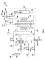
- Figure 3 depicts laboratory scale apparatus for carrying out the process of the invention for producing hydrocarbons.
- the set-up 100 includes a tubular water separation device 102 comprising the tubular ⁇ -alumina support and the mordenite membrane (MOR1 or MOR2) located against the outer surface of the support.
- the separation device 102 is located in a stainless steel module 104, with sealing of the separation device to the module being effected by means of silicone O-rings.
- the pressure inside the separation device 102 is measured by means of a pressure measurement device 146.
- the module 104 is located in an electrical furnace 106 controlled by a temperature control 121.
- the set-up 100 also includes a nitrogen supply line 108, for supplying nitrogen at 30 bar.
- a branch of the supply line 108 leads through a deionized water supply 110, through a mass flow controller 114, through a preheater 118 controlled by a temperature control unit 120, and into a flow line 170 which leads into the upper end of the central passageway of the separation device 102.
- a branch of the nitrogen supply line 108 also leads through a n-octane supply 112, through a mass flow controller 116, through a preheater 122 controlled by temperature control unit 124, and into the flow line 170.
- the set-up 100 also includes a supply line 130 for supplying a gaseous mixture of methane, carbon dioxide and hydrogen.
- the supply line 130 leads through a mass flow controller 134 and into the flow line 170.
- the set-up 100 further includes a supply line 132 for supplying a gaseous mixture of methane, carbon dioxide, carbon monoxide and hydrogen.
- the supply line 132 leads through a mass flow controller 136 and into the flow line 130.
- the pressure of the gaseous mixture in the flow line 130, 132 is measured by means of a pressure measurement device 140.
- the set-up 100 also includes a nitrogen supply line 150 leading into a mass flow controller 152, with a flow line 172 leading from the controller 152 into the module 104.
- the pressure in the nitrogen supply line 150 is measured by means of the pressure measurement device 154.
- nitrogen (or any other gas chosen) sweep gas passes along the outer tubular surface of the device 102 ie along the membrane, while the water and gaseous mixtures from the flow lines 130 or 132 pass along the inner tubular surface thereof.
- a retentate withdrawal line or conduit 160 leads from the inside of the separation device 102 to a sample switching valve 162 and from there a line 164 leads to a gas chromatography analyzer (not shown).
- a permeate withdrawal line 166 leads from the module 104, in proximity to the outlet end of the device 102, to the sample switching valve 162. Vent lines 168 are provided, with one of them leading from the line 164.
- the aim of this example was to show the system ability to carry out separation of water (W) from other species, at conditions typical of a commercial fluidized Fischer-Tropsch reactor, ie temperature around 350°C and a total pressure of 20-25 bar, ie 2000-2500kPa.
- the term 'other species' includes those likely to be present in a Fischer-Tropsch reactor: n-octane (C 8 ) as an example of hydrocarbons, H 2 , CH 4 , CO 2 and CO. These were fed as multicomponent mixtures to the membrane tube side.
- the separation device 102 was placed in the stainless steel module 104, which was sealed using graphite gaskets.
- CO was added to the above described permanent gas mixture, in the proportions shown below.
- N 2 was used as a sweep gas on the retentate side, and therefore had to be taken into account when reporting the permeate side composition.
- the mixed feedstream entered the tube side of the membrane module, while the shell side was swept with a flux of N 2 .
- Concentrations of all of the above components in the retentate (x i ) and the permeate (y i ) were analyzed by gas chromatography using thermal conductivity ('TCD') and flame ionization ('FID') detectors.
- 'TCD' thermal conductivity
- 'FID' flame ionization
- the feed flow rate for each component, F Ei was calculated as the addition of the molar flow rates thereof at the recentate and permeate sides, using equation 7.
- Permeances for each component (Per i ) were calculated using equation (8), where ⁇ P 1 and ⁇ P 2 are the driving forces (partial pressure difference between the retentate and permeate streams) for each component at the entrance and exit of the membrane module, respectively, and A the available permeation area.
- the performance of the separation is customarily expressed in terms of separation selectivities:
- the water/species i selectivity (S W/i ) was calculated as the ratio of permeances using equation (9), while the separation factors ⁇ w/i, were calculated as indicated in equation (10), ie as the quotient between the ratio of molar fractions of water and any species 'i' in the permeate and recentabe sides.
- the advantage of using the separation factor is that it is obtained directly from GC analysis, and is not affected by errors in the overall mass balance.
- Table 1 clearly shows that at temperatures and pressures typical of chose expected in a commercial fluidized bed reactor, the zeolite membrane is able to selectively separate the water from the other species found in such commercial reactor, that is, to separate the water from hydrocarbons, carbon monoxide, carbon dioxide and hydrogen.
- the water flux tends to increase with the partial pressure of water in the feed, while the separation selectivities and separation factors tend to increase with the flow of the sweep gas, which is in this case nitrogen.
- Example 2 the same set-up 100 as used in Example 1, was used; however, a different tubular separation device 102 to that described in Example 1 was used.
- porous stainless steel supports facilitates the industrial application of this invention because of their superior mechanical strength, as compared to the alpha-alumina tubular supports used in Example 1.
- Tables 2 and 3 clearly show that the ZSM-5 membranes, deposited on a porous stainless steel support, are able to selectively separate water from hydrocarbons, carbon monoxide. carbon dioxide and hydrogen, at condicions similar to those found in commercial fluidized Fischer-Tropsch reactors.
- the water flux also showed a tendency to increase with the partial pressure of water in the feed, while the separation selectivities and separation factors showed a tendency to increase with the flow of the sweep gas (in this case nitrogen), or more accurately, with the partial pressure of the sweep gas in the permeate.
- the sweep gas in this case nitrogen
- Example 2 the same ZSM5P2 membrane used in Example 2 was used, but the temperature range was expanded to include lower temperatures.
- the separation factors and separation selectivities shown in Table 4 are higher at the lower temperatures (eg 150°C and 196°C), while there is not much difference in the separation selectivities and separation factors in the temperature range of 241°C to 359°C (Tables 3 and 4) at similar sweep gas (in this example, nitrogen) flow rates or, more accurately, at similar partial pressures of the sweep gas in the retentate.
- similar sweep gas in this example, nitrogen
- zeolite membranes are able to separate water from hydrocarbons, carbon monoxide, carbon dioxide and hydrogen at temperatures typical of slurry bed Fischer-Tropsch commercial reactors operating with either cobalt or iron based catalysts, ie at 190°C to 260°C, as well as at temperatures typical of fluidized Fischer-Tropsch commercial reactors operating with iron based catalysts, ie at 320°C to 360°C.
- the zeolite membrane noc may be in contact with the catalyst particles, as would be the case if the separation devices of Examples 1 to 3 were located directly in a fluidized bed so that the membrane would be in direcr contact with the fluidized bed; this is in order to avoid possible attrition of the zeolite membrane caused by its contact with the fluidized catalyst particles.
- the zeolite membrane is deposited on the opposite side of the porous support to that which would be in contact with the catalyst particles.
- This can be achieved, in practice, by depositing a zeolite membrane on the internal surface of a porous stainless steel support and introducing the sweep gas into the tube side of the membrane. Therefore, the effect of feeding the sweep gas through the tube side of the membrane, while passing the water and the mixtures of hydrocarbons, carbon dioxide, carbon monoxide and hydrogen along the shell side of the tubular membrane was investigated.
- This example illustrates the suitability of zeolite membranes for the separation of water from hydrocarbons, carbon monoxide, carbon dioxide and hydrogen in a slurry bed reactor.
- the feed line 170 is, in Figure 4, connected to the bottom end of the tubular separation device 102, while the feed line 172 is connected to the bottom end of the stainless steel module 104.
- the permeate line 166 is connected to the upper end of the stainless steel module 104 while the retentate line 160 is connected to the upper end of the tubular separation device 102.
- the n-octane supply 112 is linked (i) to the gaseous mixture flow line 130, with the gaseous mixture therein consisting of propane, methane, carbon dioxide and hydrogen, and (ii) to the gaseous supply line 132, which now feeds pure carbon monoxide.
- the purpose is to saturate the gaseous components in lines 130 and 132 with n-octane.
- the system 200 includes a vessel 202 containing n-octane.
- the inside of the tubular separation device 102 is now filled with n-octane by means of a line 204.
- n-octane simulates the liquid hydrocarbons present in a commercial Fischer-Tropsch slurry bed reactor operating with either iron or cobalt based catalysts, and its level inside the tubular zeolite membrane 102 is controlled by means of the retentate line 160, which enters the vessel 202, therefore equalizing the pressure between the vessel 202 and the inside of the separation device 102.
- a line 206 connects the retentate coming from the inside of the tubular separation device 102 via the vessel 202 to the sample switching valve 162.
- the pressure in the permeate line 166 is measured with a pressure measurement device 208, while the pressure of the sweep gas supply 108 is measured with a pressure measuring device 210.
- Tables 6 to 8 clearly demonstrate that these zeolite membranes are able to selectively remove water from a hydrocarbon in the liquid phase, saturated and containing bubbles of carbon monoxide, carbon dioxide, hydrogen, methane and gaseous hydrocarbons such as propane, at temperatures typical of those expected in a commercial slurry bed Fischer-Tropsch reactor operating with either iron or cobalt based catalysts.
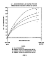
- the Anderson Fischer-Tropsch kinetic expression for an iron based Fischer-Tropsch catalyst was used to simulate the (H 2 +CO) conversion level at different positions in the Fischer-Tropsch reactor and at different degrees of in-situ extraction of the reaction water.
- the reactor operating conditions were such that the temperature was 240°C, under 20 bar (2000kPa) pressure and a feed composition of 66 vol% of hydrogen, and 34 vol% of carbon monoxide without a recycle.
- the cases that were studied were as follows:
- Figure 5 shows the per pass (H 2 +CO) conversion percentage versus the position in the reactor. From this Figure, it is obvious that the removal of reaction water results in higher (H 2 +CO) conversion levels, and therefore a higher reactor productivity.
- This specific example illustrates that a decrease in the reaction water partial pressure due to the presence of a zeolite membrane inside the Fischer-Tropsch reactor operating with a cobalt based catalyst, to values below a specific maximum (6 bar), permits the process to operate at a higher (H 2 +CO) per pass conversion than could otherwise be practically achieved. Simultaneously the catalyst is exposed to a considerably reduced reoxidation threat, in stark contrast to the experience from the conventional reactor operating at the same high (H 2 +CO) per pass conversions.
- a typical supported Fischer-Tropsch cobalt catalyst shows a high rate of water induced deactivation at high water partial pressures, typically 6 bar (600kPa) or higher. In order to maintain the catalyst activity, it is therefore necessary to operate at conditions that result in water partial pressures of less than 6 bar (600kPa).
- Water also shows a negative effect on the stability of the active iron based Fischer- Tropsch catalysts. Higher partial pressures of water result in faster reoxidation rates of the iron catalyst.
- the active iron Fischer-Tropsch catalyst is in either a metallic or a carbided form. Once it is reoxidized by the water molecules, it becomes inactive for the Fischer-Tropsch reaction.
- the reoxidizing effect of water is well known by persons of ordinary skill in the Fischer-Tropsch field, and is well documented in literature.
- the third negative effect of water is the lowering of the mechanical strength of the Fischer-Tropsch catalyst particles. It has been repeatedly observed that the mechanical strength of the reduced/carbided precipitated iron Fischer-Tropsch catalyst is much higher than after reoxidation has taken place. Therefore, when the water reoxidizes the catalyst it also weakens it mechanically. In a slurry bed Fischer-Tropsch reactor, operating with a precipitated iron based catalyst, this mechanical weakening of the catalyst particles causes major problems in the separation of the catalyst particles from the hydrocarbon products in the wax range.
- the selective extraction of the reaction water from the Fischer-Tropsch reactors in accordance with the invention has a potential of offering considerable advantages in terms of the operation of the conventional reactors. Higher production rates per reactor volume and better catalyst protection from reoxidation and mechanical degradation during operation, and therefore longer catalyst lifetime will be obtained.
- zeolite based membranes can be successfully utilized for the selective removal of water from a hydrocarbon species and a fraction of permanent gas mixture that is maintained under Fischer-Tropsch reaction conditions.
- the separation devices used in the process of the invention can also be made in accordance with the procedures outlined in J. Membrane Science, 149 (1958) pg 99-114, "Synthesis, characterization ahd separation properties of a composite mordenite/ZSM-5/chabazite hydrophilic membrane", by E. Piera, M.A. Salomon, J. Coronas, M. Menendez and J. Santamaria.
Landscapes
- Chemical & Material Sciences (AREA)
- Organic Chemistry (AREA)
- Chemical Kinetics & Catalysis (AREA)
- Engineering & Computer Science (AREA)
- Combustion & Propulsion (AREA)
- General Chemical & Material Sciences (AREA)
- Oil, Petroleum & Natural Gas (AREA)
- Organic Low-Molecular-Weight Compounds And Preparation Thereof (AREA)
- Separation Using Semi-Permeable Membranes (AREA)
- Catalysts (AREA)
- Production Of Liquid Hydrocarbon Mixture For Refining Petroleum (AREA)
- Devices And Processes Conducted In The Presence Of Fluids And Solid Particles (AREA)
Claims (14)
- Procédé de production d'hydrocarbures, ledit procédé comprenant :la possibilité pour des produits réactifs faisant partie d'un milieu de réaction dans une zone de réaction de réagir dans des conditions de réaction de façon à former des produits primaires d'hydrocarbures, l'eau étant formée comme sous-produit ; etla possibilité pour l'eau en tant que sous-produit, lors de sa formation dans les conditions de réaction, de s'infiltrer à travers une membrane pouvant enlever, de façon sélective, l'eau du milieu de réaction, la séparant ainsi du milieu de réaction.
- Procédé selon la revendication 1, selon lequel les produits réactifs sont sous forme gazeuse et comprennent du monoxyde de carbone et de l'hydrogène avec un catalyseur particulaire de Fischer-Tropsch faisant partie également du milieu de réaction et les conditions de réaction étant telles que le monoxyde de carbone et l'hydrogène réagissent en présence du catalyseur de Fischer-Tropsch et selon la réaction de Fischer-Tropsch afin de produire, en tant que produits hydrocarbures primaires, un(des) produit(s) liquide(s) et/ou gazeux hydrocarbures dérivé(s) de Fischer-Tropsch.
- Procédé selon la revendication 2, selon lequel la zone de réaction est constituée d'un réacteur à lit bouillonnant (10), lit bouillonnant comprenant des produits hydrocarbures liquides, des produits hydrocarbures gazeux, de l'eau, des produits réactifs gazeux et des particules de catalyseur, la membrane étant ainsi positionnée à l'intérieur du lit bouillonnant et du milieu de réaction et comprenant de même des produits hydrocarbures liquides, des produits hydrocarbures gazeux, de l'eau, des produits réactifs gazeux et des particules de catalyseur.
- Procédé selon la revendication 2, selon lequel la zone de réaction est constituée d'un réacteur à lit fluidisé (50), lit bouillonnant comprenant des produits hydrocarbures gazeux, de l'eau, des produits réactifs gazeux et des particules de catalyseur, la membrane étant ainsi positionnée à l'intérieur du lit fluidisé et du milieu de réaction et comprenant, de même, des produits hydrocarbures gazeux, de l'eau, des produits réactifs gazeux et des particules de catalyseur.
- Procédé selon l'une quelconque des revendications 1 à 4 incluse, selon lequel la membrane est supportée par un support perméable à l'eau de telle façon que la membrane possède un côté d'entrée d'eau et un côté de sortie d'eau, l'eau en tant que sous-produit pénétrant ainsi dans la membrane par son côté d'entrée d'eau, s'infiltrant à travers la membrane et sortant de la membrane par son côté de sortie d'eau, le support et la membrane formant ainsi un dispositif de séparation d'eau (26, 102).
- Procédé selon la revendication 5, comprenant le passage d'un gaz inerte de balayage le long du support à proximité du côté de sortie d'eau de la membrane pour entraíner l'eau s'infiltrant à travers la membrane, constituant ainsi une force d'entraínement pour la perméation de l'eau à travers la membrane.
- Procédé selon la revendication 6, selon lequel le support est de forme tubulaire, la membrane étant prévue sur la surface interne ou externe du support tubulaire et le gaz de balayage traversant l'intérieur de la membrane.
- Procédé selon la revendication 7, selon lequel le gaz de balayage pénètre dans la zone de réaction à travers une conduite (28) connectée à l'intérieur du support tubulaire à ou près de son extrémité, traverse le support et sort de la zone de réaction par une autre conduite (30) conduisant du support à ou près de son autre extrémité en dehors de la zone de réaction.
- Procédé selon l'une quelconque des revendications 5 à 8 incluse, selon lequel la membrane est un matériau poreux de zéolithe choisi parmi la mordenite, le ZSM-5, la zéolithe A et la chabazite.
- Procédé selon l'une quelconque des revendications 5 à 9 incluse, selon lequel le support perméable à l'eau est en acier inoxydable poreux.
- Réacteur (10, 50) pour la production d'hydrocarbures, comprenant :un récipient de réacteur (12) possédant une zone de lit de catalyseur (14, 52) qui en utilisation contiendra un lit bouillonnant ou fluidisé de particules de catalyseur suspendues ou fluidisées dans un produit liquide et/ou gazeux d'hydrocarbures ;une entrée de gaz dans le récipient à un bas niveau dans la zone de lit de catalyseur pour l'introduction de produits réactifs gazeux dans le récipient ;une sortie de gaz dans un volume vide (20) du récipient au-dessus de la zone de lit de catalyseur pour l'extraction des produits réactifs gazeux et des produits gazeux n'ayant pas réagi du récipient ; etune membrane pouvant enlever, de façon sélective, l'eau d'un milieu de réaction, positionnée dans la zone de lit de catalyseur de telle façon que toute l'eau en tant que sous-produit qui est formée dans la zone de réaction lors de la réaction des produits réactifs gazeux pour former le produit hydrocarbure liquide et/ou gazeux puisse s'infiltrer à travers la membrane.
- Réacteur (10, 50) selon la revendication 11, dans lequel la membrane est supportée par un support perméable à l'eau de telle façon que la membrane possède un côté d'entrée d'eau et un côté de sortie d'eau, l'eau en tant que sous-produit pénétrant ainsi en utilisation la membrane par son côté d'entrée d'eau, s'infiltrant à travers la membrane et sortant de la membrane par son côté de sortie d'eau, le support et la membrane formant ainsi un dispositif de séparation d'eau (26, 102).
- Réacteur (10, 50) selon la revendication 12, dans lequel le support est de forme tubulaire avec un passage central, la membrane étant prévue sur la surface interne ou externe du support tubulaire.
- Réacteur (10, 50) selon la revendication 13, dans lequel, une conduite d'alimentation en gaz de balayage (28) est connectée à une extrémité du passage central de la membrane tubulaire pour fournir un gaz inerte de balayage dans et le long du passage central de la membrane, avec une conduite d'extraction de gaz de balayage (30) évacuant à partir de l'autre extrémité du passage central de membrane.
Applications Claiming Priority (3)
| Application Number | Priority Date | Filing Date | Title |
|---|---|---|---|
| ZA9805093 | 1998-06-11 | ||
| ZA985093 | 1998-06-11 | ||
| PCT/IB1999/001043 WO1999064380A1 (fr) | 1998-06-11 | 1999-06-07 | Production d'hydrocarbures |
Publications (2)
| Publication Number | Publication Date |
|---|---|
| EP1089956A1 EP1089956A1 (fr) | 2001-04-11 |
| EP1089956B1 true EP1089956B1 (fr) | 2003-11-05 |
Family
ID=25587071
Family Applications (1)
| Application Number | Title | Priority Date | Filing Date |
|---|---|---|---|
| EP99923776A Expired - Lifetime EP1089956B1 (fr) | 1998-06-11 | 1999-06-07 | Production d'hydrocarbures |
Country Status (14)
| Country | Link |
|---|---|
| US (1) | US6403660B1 (fr) |
| EP (1) | EP1089956B1 (fr) |
| CN (1) | CN1170791C (fr) |
| AT (1) | ATE253539T1 (fr) |
| AU (1) | AU755804B2 (fr) |
| CA (1) | CA2334731A1 (fr) |
| DE (1) | DE69912605D1 (fr) |
| EG (1) | EG22434A (fr) |
| GC (1) | GC0000059A (fr) |
| ID (1) | ID28071A (fr) |
| NO (1) | NO20006256L (fr) |
| PE (1) | PE20000960A1 (fr) |
| RU (1) | RU2220938C2 (fr) |
| WO (1) | WO1999064380A1 (fr) |
Families Citing this family (31)
| Publication number | Priority date | Publication date | Assignee | Title |
|---|---|---|---|---|
| US6914082B2 (en) | 2001-12-14 | 2005-07-05 | Conocophillips Company | Slurry bubble reactor operated in well-mixed gas flow regime |
| WO2003057338A2 (fr) * | 2001-12-28 | 2003-07-17 | Conocophillips Company | Separation de l'eau dans des syntheses de fischer-tropsch |
| US6809122B2 (en) * | 2001-12-28 | 2004-10-26 | Conocophillips Company | Method for reducing the maximum water concentration in a multi-phase column reactor |
| US6720358B2 (en) | 2001-12-28 | 2004-04-13 | Conocophillips Company | Water stripping and catalyst/liquid product separation system |
| US7001927B2 (en) | 2001-12-28 | 2006-02-21 | Conocophillips Company | Water removal in Fischer-Tropsch processes |
| US6956063B2 (en) | 2001-12-28 | 2005-10-18 | Conocophillips Company | Method for reducing water concentration in a multi-phase column reactor |
| WO2003089103A2 (fr) | 2002-04-16 | 2003-10-30 | Conocophilips Company | Systeme de separation de solides/liquides optimise pour convertisseurs multiphases |
| US6833078B2 (en) | 2002-09-13 | 2004-12-21 | Conocophillips Company | Solid-liquid separation system |
| US6878655B2 (en) * | 2002-09-20 | 2005-04-12 | Conocophillips Company | Method and apparatus for the regeneration of hydrocarbon synthesis catalysts |
| US7067562B2 (en) * | 2002-12-20 | 2006-06-27 | Conocophillips Company | Iron-based Fischer-Tropsch catalysts and methods of making and using |
| US7230035B2 (en) * | 2002-12-30 | 2007-06-12 | Conocophillips Company | Catalysts for the conversion of methane to synthesis gas |
| US6800664B1 (en) * | 2003-05-23 | 2004-10-05 | Conocophillips Company | Conjoined reactor system |
| EP1524254B1 (fr) * | 2003-10-17 | 2010-06-23 | Technische Universiteit Delft | Procédé pour la séparation d'eau d'un mélange réactionnel au moyen d'une membrane hydroxy sodalite |
| US7276105B2 (en) * | 2004-06-28 | 2007-10-02 | Chevron U.S.A. Inc. | Separation of water from Fischer-Tropsch product |
| CN1297523C (zh) * | 2005-04-01 | 2007-01-31 | 上海兖矿能源科技研发有限公司 | 一种费托合成反应水的处理方法 |
| CN100457253C (zh) * | 2006-01-25 | 2009-02-04 | 上海兖矿能源科技研发有限公司 | 用于费托合成的流化床反应器 |
| US20080260631A1 (en) | 2007-04-18 | 2008-10-23 | H2Gen Innovations, Inc. | Hydrogen production process |
| WO2009088785A1 (fr) * | 2007-12-31 | 2009-07-16 | Chevron U.S.A. Inc. | Réacteur à membrane avec déshydratation in situ et son procédé d'utilisation |
| ITMI20080079A1 (it) * | 2008-01-18 | 2009-07-19 | Eni Spa | Processo per la purificazione di una corrente acquosa proveniente dalla reazione di fischer-tropsch |
| JP5364717B2 (ja) | 2008-09-30 | 2013-12-11 | 独立行政法人石油天然ガス・金属鉱物資源機構 | 触媒分離システム |
| EP2192090A1 (fr) * | 2008-12-01 | 2010-06-02 | Technische Universiteit Delft | Procédé de production d'eau ultrapure à l'aide d'une membrane |
| US8425854B1 (en) * | 2011-10-07 | 2013-04-23 | Chevron U.S.A. Inc. | Process for providing hydrogen to a synthesis gas conversion reaction |
| US9359558B2 (en) * | 2012-11-29 | 2016-06-07 | General Electric Company | Carbon to liquids system and method of operation |
| US10076620B2 (en) * | 2012-12-22 | 2018-09-18 | Dmf Medical Incorporated | Anesthetic circuit having a hollow fiber membrane |
| US20150147563A1 (en) * | 2013-11-27 | 2015-05-28 | Ronald Stanis | Air conditioning laminate and method |
| US10889762B2 (en) * | 2016-12-09 | 2021-01-12 | Velocys Technologies Limited | Process for operating a highly productive tubular reactor |
| CN108545759A (zh) * | 2018-04-18 | 2018-09-18 | 中国天辰工程有限公司 | 一种修饰的硅铝磷分子筛的制备方法及其评价装置 |
| DE102019207540B4 (de) | 2019-05-23 | 2023-07-06 | Fraunhofer-Gesellschaft zur Förderung der angewandten Forschung e.V. | Verfahren zur Herstellung von Polyoxymethylendimethylether |
| JP7151832B1 (ja) * | 2021-06-11 | 2022-10-12 | Jfeスチール株式会社 | 膜反応器における未利用ガスの再利用方法 |
| WO2023112800A1 (fr) * | 2021-12-17 | 2023-06-22 | 日本碍子株式会社 | Système de synthèse et procédé de synthèse de carburant liquide |
| CN117157379A (zh) * | 2021-12-17 | 2023-12-01 | 日本碍子株式会社 | 液体燃料合成系统以及液体燃料合成方法 |
Family Cites Families (2)
| Publication number | Priority date | Publication date | Assignee | Title |
|---|---|---|---|---|
| US4801573A (en) * | 1987-10-23 | 1989-01-31 | 501 Den Norske Stats Oljeslenskap A.S. | Catalyst for production of hydrocarbons |
| US5599849A (en) * | 1993-01-27 | 1997-02-04 | Sasol Chemical Industries (Proprietary) Limited | Process for producing liquid and, optionally, gaseous products from gaseous reactants |
-
1999
- 1999-06-07 EP EP99923776A patent/EP1089956B1/fr not_active Expired - Lifetime
- 1999-06-07 AU AU40532/99A patent/AU755804B2/en not_active Expired
- 1999-06-07 RU RU2001101174/15A patent/RU2220938C2/ru not_active IP Right Cessation
- 1999-06-07 DE DE69912605T patent/DE69912605D1/de not_active Expired - Lifetime
- 1999-06-07 CN CNB998072362A patent/CN1170791C/zh not_active Expired - Lifetime
- 1999-06-07 AT AT99923776T patent/ATE253539T1/de not_active IP Right Cessation
- 1999-06-07 WO PCT/IB1999/001043 patent/WO1999064380A1/fr not_active Ceased
- 1999-06-07 ID IDW20010069A patent/ID28071A/id unknown
- 1999-06-07 CA CA002334731A patent/CA2334731A1/fr not_active Abandoned
- 1999-06-09 GC GCP1999174 patent/GC0000059A/xx active
- 1999-06-09 PE PE1999000516A patent/PE20000960A1/es not_active Application Discontinuation
- 1999-06-10 EG EG69699A patent/EG22434A/xx active
-
2000
- 2000-12-05 US US09/730,472 patent/US6403660B1/en not_active Expired - Lifetime
- 2000-12-08 NO NO20006256A patent/NO20006256L/no not_active Application Discontinuation
Also Published As
| Publication number | Publication date |
|---|---|
| RU2220938C2 (ru) | 2004-01-10 |
| AU755804B2 (en) | 2002-12-19 |
| DE69912605D1 (de) | 2003-12-11 |
| ID28071A (id) | 2001-05-03 |
| GC0000059A (en) | 2004-06-30 |
| AU4053299A (en) | 1999-12-30 |
| US6403660B1 (en) | 2002-06-11 |
| EP1089956A1 (fr) | 2001-04-11 |
| PE20000960A1 (es) | 2000-09-28 |
| NO20006256D0 (no) | 2000-12-08 |
| ATE253539T1 (de) | 2003-11-15 |
| EG22434A (en) | 2003-01-29 |
| WO1999064380A1 (fr) | 1999-12-16 |
| CA2334731A1 (fr) | 1999-12-16 |
| CN1305444A (zh) | 2001-07-25 |
| CN1170791C (zh) | 2004-10-13 |
| NO20006256L (no) | 2001-02-06 |
Similar Documents
| Publication | Publication Date | Title |
|---|---|---|
| EP1089956B1 (fr) | Production d'hydrocarbures | |
| Mei et al. | High-flux CHA zeolite membranes for H2 separations | |
| Ciavarella et al. | Isobutane dehydrogenation in a membrane reactor: influence of the operating conditions on the performance | |
| AU766490B2 (en) | Hydrogen-selective silica based membrane | |
| US5507856A (en) | Hydrogen recovery by adsorbent membranes | |
| Gallucci et al. | An experimental study of CO2 hydrogenation into methanol involving a zeolite membrane reactor | |
| EP1051459B1 (fr) | Hydrodesulfuration de liquides hydrocarbones de puits de gaz par l'utilisation d'hydrogene obtenu a partir de gaz de synthese | |
| Espinoza et al. | Use of membranes in Fischer-Tropsch reactors | |
| EP2074057B1 (fr) | Procédé d'extraction d'hydrogène d'un mélange gazeux | |
| US7938893B2 (en) | Membrane reactor for H2S, CO2 and H2 separation | |
| van Veen et al. | Studies on the performance stability of mixed conducting BSCFO membranes in medium temperature oxygen permeation | |
| EP1024111A1 (fr) | Procédé et dispositif pour la préparation d'hydrogène de haute pureté | |
| Yue et al. | Synthesis of Cu–ZnO–Pt@ HZSM-5 catalytic membrane reactor for CO2 hydrogenation to dimethyl ether | |
| van de Graaf et al. | Application of a zeolite membrane reactor in the metathesis of propene | |
| Chang et al. | Propane dehydrogenation over a hydrogen permselective membrane reactor | |
| AU2002328852B2 (en) | Process for the production of liquid hydrocarbons | |
| JPS6260129B2 (fr) | ||
| AU2002328852A1 (en) | Process for the production of liquid hydrocarbons | |
| Xiongfu et al. | Synthesis and characterization of Fe-MFI zeolite membrane on a porous α-Al2O3 tube | |
| Sea et al. | Methanol synthesis from carbon dioxide and hydrogen using a ceramic memebrane reactor | |
| WO2018004994A1 (fr) | Réacteur à membrane à lit fluidisé | |
| Amanipour et al. | Evaluation of a tubular nano-composite ceramic membrane for hydrogen separation in methane steam reforming reaction | |
| Ostrowski et al. | Comparative study of the partial oxidation of methane to synthesis gas in fixed-bed and fluidized-bed membrane reactors.: Part II–Development of membranes and catalytic measurements | |
| Bajpai et al. | Deactivation studies of nickel catalysts used in the methanation of carbon monoxide | |
| Tavolaro et al. | The preparation of transition metal-containing mordenite catalytic tubular composite membranes |
Legal Events
| Date | Code | Title | Description |
|---|---|---|---|
| PUAI | Public reference made under article 153(3) epc to a published international application that has entered the european phase |
Free format text: ORIGINAL CODE: 0009012 |
|
| 17P | Request for examination filed |
Effective date: 20010110 |
|
| AK | Designated contracting states |
Kind code of ref document: A1 Designated state(s): AT BE CH CY DE DK ES FI FR GB GR IE IT LI LU MC NL PT SE |
|
| 17Q | First examination report despatched |
Effective date: 20021002 |
|
| GRAH | Despatch of communication of intention to grant a patent |
Free format text: ORIGINAL CODE: EPIDOS IGRA |
|
| GRAS | Grant fee paid |
Free format text: ORIGINAL CODE: EPIDOSNIGR3 |
|
| GRAA | (expected) grant |
Free format text: ORIGINAL CODE: 0009210 |
|
| AK | Designated contracting states |
Kind code of ref document: B1 Designated state(s): AT BE CH CY DE DK ES FI FR GB GR IE IT LI LU MC NL PT SE |
|
| PG25 | Lapsed in a contracting state [announced via postgrant information from national office to epo] |
Ref country code: LI Free format text: LAPSE BECAUSE OF FAILURE TO SUBMIT A TRANSLATION OF THE DESCRIPTION OR TO PAY THE FEE WITHIN THE PRESCRIBED TIME-LIMIT Effective date: 20031105 Ref country code: FI Free format text: LAPSE BECAUSE OF FAILURE TO SUBMIT A TRANSLATION OF THE DESCRIPTION OR TO PAY THE FEE WITHIN THE PRESCRIBED TIME-LIMIT Effective date: 20031105 Ref country code: CY Free format text: LAPSE BECAUSE OF FAILURE TO SUBMIT A TRANSLATION OF THE DESCRIPTION OR TO PAY THE FEE WITHIN THE PRESCRIBED TIME-LIMIT Effective date: 20031105 Ref country code: CH Free format text: LAPSE BECAUSE OF FAILURE TO SUBMIT A TRANSLATION OF THE DESCRIPTION OR TO PAY THE FEE WITHIN THE PRESCRIBED TIME-LIMIT Effective date: 20031105 Ref country code: BE Free format text: LAPSE BECAUSE OF FAILURE TO SUBMIT A TRANSLATION OF THE DESCRIPTION OR TO PAY THE FEE WITHIN THE PRESCRIBED TIME-LIMIT Effective date: 20031105 Ref country code: AT Free format text: LAPSE BECAUSE OF FAILURE TO SUBMIT A TRANSLATION OF THE DESCRIPTION OR TO PAY THE FEE WITHIN THE PRESCRIBED TIME-LIMIT Effective date: 20031105 |
|
| REG | Reference to a national code |
Ref country code: GB Ref legal event code: FG4D |
|
| REG | Reference to a national code |
Ref country code: CH Ref legal event code: EP |
|
| REF | Corresponds to: |
Ref document number: 69912605 Country of ref document: DE Date of ref document: 20031211 Kind code of ref document: P |
|
| REG | Reference to a national code |
Ref country code: IE Ref legal event code: FG4D |
|
| PG25 | Lapsed in a contracting state [announced via postgrant information from national office to epo] |
Ref country code: SE Free format text: LAPSE BECAUSE OF FAILURE TO SUBMIT A TRANSLATION OF THE DESCRIPTION OR TO PAY THE FEE WITHIN THE PRESCRIBED TIME-LIMIT Effective date: 20040205 Ref country code: GR Free format text: LAPSE BECAUSE OF FAILURE TO SUBMIT A TRANSLATION OF THE DESCRIPTION OR TO PAY THE FEE WITHIN THE PRESCRIBED TIME-LIMIT Effective date: 20040205 Ref country code: DK Free format text: LAPSE BECAUSE OF FAILURE TO SUBMIT A TRANSLATION OF THE DESCRIPTION OR TO PAY THE FEE WITHIN THE PRESCRIBED TIME-LIMIT Effective date: 20040205 |
|
| PG25 | Lapsed in a contracting state [announced via postgrant information from national office to epo] |
Ref country code: DE Free format text: LAPSE BECAUSE OF FAILURE TO SUBMIT A TRANSLATION OF THE DESCRIPTION OR TO PAY THE FEE WITHIN THE PRESCRIBED TIME-LIMIT Effective date: 20040206 |
|
| PG25 | Lapsed in a contracting state [announced via postgrant information from national office to epo] |
Ref country code: ES Free format text: LAPSE BECAUSE OF FAILURE TO SUBMIT A TRANSLATION OF THE DESCRIPTION OR TO PAY THE FEE WITHIN THE PRESCRIBED TIME-LIMIT Effective date: 20040216 |
|
| REG | Reference to a national code |
Ref country code: CH Ref legal event code: PL |
|
| PGFP | Annual fee paid to national office [announced via postgrant information from national office to epo] |
Ref country code: GB Payment date: 20040602 Year of fee payment: 6 |
|
| PG25 | Lapsed in a contracting state [announced via postgrant information from national office to epo] |
Ref country code: LU Free format text: LAPSE BECAUSE OF NON-PAYMENT OF DUE FEES Effective date: 20040607 Ref country code: IE Free format text: LAPSE BECAUSE OF NON-PAYMENT OF DUE FEES Effective date: 20040607 |
|
| PG25 | Lapsed in a contracting state [announced via postgrant information from national office to epo] |
Ref country code: MC Free format text: LAPSE BECAUSE OF NON-PAYMENT OF DUE FEES Effective date: 20040630 |
|
| ET | Fr: translation filed | ||
| PLBE | No opposition filed within time limit |
Free format text: ORIGINAL CODE: 0009261 |
|
| STAA | Information on the status of an ep patent application or granted ep patent |
Free format text: STATUS: NO OPPOSITION FILED WITHIN TIME LIMIT |
|
| 26N | No opposition filed |
Effective date: 20040806 |
|
| PG25 | Lapsed in a contracting state [announced via postgrant information from national office to epo] |
Ref country code: FR Free format text: LAPSE BECAUSE OF NON-PAYMENT OF DUE FEES Effective date: 20050228 |
|
| REG | Reference to a national code |
Ref country code: IE Ref legal event code: MM4A |
|
| REG | Reference to a national code |
Ref country code: FR Ref legal event code: ST |
|
| PG25 | Lapsed in a contracting state [announced via postgrant information from national office to epo] |
Ref country code: IT Free format text: LAPSE BECAUSE OF NON-PAYMENT OF DUE FEES;WARNING: LAPSES OF ITALIAN PATENTS WITH EFFECTIVE DATE BEFORE 2007 MAY HAVE OCCURRED AT ANY TIME BEFORE 2007. THE CORRECT EFFECTIVE DATE MAY BE DIFFERENT FROM THE ONE RECORDED. Effective date: 20050607 Ref country code: GB Free format text: LAPSE BECAUSE OF NON-PAYMENT OF DUE FEES Effective date: 20050607 |
|
| GBPC | Gb: european patent ceased through non-payment of renewal fee |
Effective date: 20050607 |
|
| PG25 | Lapsed in a contracting state [announced via postgrant information from national office to epo] |
Ref country code: PT Free format text: LAPSE BECAUSE OF NON-PAYMENT OF DUE FEES Effective date: 20040405 |
|
| REG | Reference to a national code |
Ref country code: HK Ref legal event code: WD Ref document number: 1035361 Country of ref document: HK |
|
| PGFP | Annual fee paid to national office [announced via postgrant information from national office to epo] |
Ref country code: NL Payment date: 20090603 Year of fee payment: 11 |
|
| REG | Reference to a national code |
Ref country code: NL Ref legal event code: V1 Effective date: 20110101 |
|
| PG25 | Lapsed in a contracting state [announced via postgrant information from national office to epo] |
Ref country code: NL Free format text: LAPSE BECAUSE OF NON-PAYMENT OF DUE FEES Effective date: 20110101 |