EP1090253B1 - Luminaire dote de lamelles a changement graduel de profil - Google Patents
Luminaire dote de lamelles a changement graduel de profil Download PDFInfo
- Publication number
- EP1090253B1 EP1090253B1 EP00920724A EP00920724A EP1090253B1 EP 1090253 B1 EP1090253 B1 EP 1090253B1 EP 00920724 A EP00920724 A EP 00920724A EP 00920724 A EP00920724 A EP 00920724A EP 1090253 B1 EP1090253 B1 EP 1090253B1
- Authority
- EP
- European Patent Office
- Prior art keywords
- luminaire
- relief
- lamellae
- reflectors
- lamella
- Prior art date
- Legal status (The legal status is an assumption and is not a legal conclusion. Google has not performed a legal analysis and makes no representation as to the accuracy of the status listed.)
- Expired - Lifetime
Links
- 241000446313 Lamella Species 0.000 claims abstract description 30
- 230000007423 decrease Effects 0.000 claims abstract description 14
- 230000003247 decreasing effect Effects 0.000 claims description 7
- 238000000149 argon plasma sintering Methods 0.000 claims description 3
- 238000007373 indentation Methods 0.000 claims 1
- 241000283070 Equus zebra Species 0.000 abstract 1
- 229910052751 metal Inorganic materials 0.000 description 2
- 239000002184 metal Substances 0.000 description 2
- 229910052782 aluminium Inorganic materials 0.000 description 1
- XAGFODPZIPBFFR-UHFFFAOYSA-N aluminium Chemical compound [Al] XAGFODPZIPBFFR-UHFFFAOYSA-N 0.000 description 1
- 238000002048 anodisation reaction Methods 0.000 description 1
- 230000000694 effects Effects 0.000 description 1
- 230000002349 favourable effect Effects 0.000 description 1
- 238000003384 imaging method Methods 0.000 description 1
- 238000001746 injection moulding Methods 0.000 description 1
- 238000004519 manufacturing process Methods 0.000 description 1
- 239000000463 material Substances 0.000 description 1
- QSHDDOUJBYECFT-UHFFFAOYSA-N mercury Chemical compound [Hg] QSHDDOUJBYECFT-UHFFFAOYSA-N 0.000 description 1
- 238000007747 plating Methods 0.000 description 1
- 230000007704 transition Effects 0.000 description 1
Images


Classifications
-
- F—MECHANICAL ENGINEERING; LIGHTING; HEATING; WEAPONS; BLASTING
- F21—LIGHTING
- F21V—FUNCTIONAL FEATURES OR DETAILS OF LIGHTING DEVICES OR SYSTEMS THEREOF; STRUCTURAL COMBINATIONS OF LIGHTING DEVICES WITH OTHER ARTICLES, NOT OTHERWISE PROVIDED FOR
- F21V11/00—Screens not covered by groups F21V1/00, F21V3/00, F21V7/00 or F21V9/00
- F21V11/02—Screens not covered by groups F21V1/00, F21V3/00, F21V7/00 or F21V9/00 using parallel laminae or strips, e.g. of Venetian-blind type
-
- F—MECHANICAL ENGINEERING; LIGHTING; HEATING; WEAPONS; BLASTING
- F21—LIGHTING
- F21V—FUNCTIONAL FEATURES OR DETAILS OF LIGHTING DEVICES OR SYSTEMS THEREOF; STRUCTURAL COMBINATIONS OF LIGHTING DEVICES WITH OTHER ARTICLES, NOT OTHERWISE PROVIDED FOR
- F21V13/00—Producing particular characteristics or distribution of the light emitted by means of a combination of elements specified in two or more of main groups F21V1/00 - F21V11/00
- F21V13/02—Combinations of only two kinds of elements
- F21V13/10—Combinations of only two kinds of elements the elements being reflectors and screens
Definitions
- the invention relates to a luminaire comprising:
- Such a luminaire is known from European patent EP 0 286 890 B1.
- the lamellae in the known luminaire have a relief of folds which extend along the outer edge and which have a profile depth.
- the profile depth in the known lamp is a level difference in the surface of the lamella which is obtained through deformation of the lamella surface.
- the folds comprise a portion facing the observer and a portion facing away from the observer, which portions have a comparatively high and a comparatively low brightness, respectively, during the operation of the accommodated lamp.
- the folds give the lamellae in general an average, comparatively low brightness as compared with non-undulated lamellae, which brightness in the case of non-undulated lamellae is often perceived as too high by the observer.
- Those portions of the folds which are situated adjacent the lateral edges of the lamellae lead to an image of the lamellae being projected on the reflectors in the form of a light spot with brightness differences.
- the brightness differences form a light-dark striped pattern.
- a disadvantage of the known luminaire is that the light spot with a light-dark pattern is visible to the observer during operation of the accommodated electric lamp.
- FR-A1-2 485 691 shows a luminaire according to the preamble of claim 1.
- this object is achieved in that a luminaire of the kind described in the opening paragraph is characterized in that the lamella has a relief which decreases in the direction towards the lateral edge.
- the measure has a twofold effect. On the one hand, it is achieved thereby that brightness differences in the light-dark pattern resulting from the fact that the surface adjacent the lateral edges is not plane are reduced thanks to the reduced relief, and accordingly are imaged on the reflectors with smaller brightness differences. On the other hand, the brightness of the lamella surface is evened out thereby, since the decrease in brightness of this surface caused by an increasing distance of this surface to the electric lamp is compensated for by the profile which is reduced in the direction towards the lateral edge.
- the decreasing relief may be decreasing owing to a decreasing profile depth, or alternatively it may be decreasing in that the profile has a pattern which is repeated over an increasing distance each time, in which case the profile depth may be constant.
- the relief of the lamella may be built up from, for example, folds, but it may alternatively be designed as a sunken relief of, for example, pits or holes in the lamella.
- the luminaire is characterized in that the relief shows a decreasing trend in the direction towards the outer edge. A further equalization in the brightness of the lamellae from the inner edge to the outer edge is achieved thereby, so that also an equalization in the brightness of the image of the lamellae on the reflector is achieved.
- the luminaire is characterized in that the relief is at least substantially absent at the lateral edge.
- the lamella is at least substantially flat at the lateral edge of the lamella, so that brightness differences in the light-dark pattern adjacent the lateral edge of the lamella are yet further reduced. A further evening out of the image of the lamellae on the reflector is also achieved thereby.
- the luminaire is characterized in that a decrease in the relief in a direction substantially parallel to the outer edge starts at a distance of 1 to 2 cm from the lateral edge.
- the reflectors are usually provided with a comparatively diffusely reflecting material, for example aluminum which may be frosted by anodization.
- the images of the lamellae become blurred owing to the diffuse reflective of the reflectors. Images of portions of the lamellae having a relief situated at a distance greater than 1 to 2 cm from the reflectors are accordingly no longer observable as images with light-dark patterns. A gradual change in the relief can accordingly remain limited to a portion of the lamella starting from 1 to 2 cm from the lateral edges.
- the gradual change may also be discontinuous and consist in that the relief has an abrupt transition from the relevant portion of the lamella to another portion of the lamella which is at least substantially without relief, i.e. the lamella in the other portion is at least substantially plane.
- the equalization of the lamella brightness is then indeed changed abruptly by the discontinuous change from a portion with relief to a portion with an at least substantially plane surface, but this is counterbalanced by the fact that brightness differences in the light-dark pattern in the image of the lamellae on the reflector are at least substantially prevented.
- the luminaire is characterized in that the relief comprises folds which extend substantially parallel to the outer edge, or depressions and elevations.
- An attractive property of lamellae provided with reliefs in this manner is that they can be obtained in one operation, cut and profiled, during their manufacture from, for example, metal tape. A crest of a fold or a depression at the one surface of the lamella then is a valley or an elevation at the other surface of the lamella.
- the luminaire according to the invention may be designed, for example, for accommodating a straight tubular electric lamp, for example a fluorescent lamp, such as a low-pressure mercury vapor discharge lamp.
- the luminaire may alternatively be designed for an elongate lamp in which, for example, two straight, interconnected tubular portions extend next to one another.
- a lamella may be subdivided into several sub-lamellae, which sub-lamellae will each have a change in their profiles analogous to that of a single (sub-)lamella.
- the luminaire is at least substantially round or square, the lamellae may be provided crosswise in the light emission window.
- the luminaire may or may not have a housing in which the reflectors are accommodated.
- the lamellae may be manufactured by means of deformation of, for example, metal plating, but alternatively they may be manufactured by injection molding.
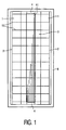
- the luminaire of Fig. 1, see also Fig. 2, has elongate reflectors 1 which are concave in the Figure but which may alternatively be plane or faceted, which are positioned substantially mutually parallel opposite one another, and which each have an edge 2, said edges defining a light emission window 3.
- the reflectors 1 are accommodated in a housing 6 in Fig. 1.
- Means 4 are present for accommodating therein an elongate electric lamp e.l. between the reflectors.
- a plurality of flat, light-scattering lamellae 10 is accommodated between the reflectors 1, transverse to the reflectors 1 and transverse to the light emission window 3.
- Fig. 2 shows the same luminaire in perspective view, viewed in a plane oblique with respect to the lamp.
- Fig. 2 shows how the lamellae 10 project through slots 5 in the reflectors 1 and are fixed therein.
- the lamellae 10 each have a convex inner edge 11 along, but at a distance from the light emission window, and a concave outer edge 12 in the light emission window 3.
- the lamellae 10 are provided with a relief 101 with a profile depth which decreases in a direction towards the lateral edge 100.
- the image 102 of the lamellae 10 projected on the reflectors 1 is a homogeneous light spot.
- the image 102 of the lamellae 10b projected on the reflectors 1 is a light spot with a light-dark striped pattern.
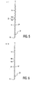
- Fig. 4 shows a lamella 10, of curved shape in the Figure, but the lamella may also have a different shape, for example one with sub-lamellae.
- the lamellae 10 have surfaces 10' with folds 13 which have a profile depth and extend along the outer edge 12.
- the Figure indicates a change in the profile depth of the folds 13 over the surface 10' of the lamella 10 by means of a change in the thickness of the lines which represent the folds 13.
- a thick line indicates a great profile depth of the relevant fold 13.
- a thin line indicates a small profile depth of the relevant fold 13.
- the maximum level difference (or profile depth) in the folds 13 is approximately 0.5 mm.
- Fig. 4 further shows that the folds 13, i.e. the portions of the surfaces 10' provided with relief 101, extend exclusively between the lateral edges 100. Portions 14 of the lamellae 10 projecting into and through the slots 5 (see Fig. 2) are not undulated.
- Fig. 5 shows a cross-section of the embodiment of the lamella 10 according to Fig. 4 taken on the line I-I.
- the profile depth in Fig. 5 decreases gradually from the inner edge 11 towards the outer edge 12 over the entire height of the lamella 10.
- the profile depth of the folds also decreases in a direction from the lateral edge 100 transversely to the lateral edge 100 (see Fig. 4). This decrease in the profile depth of the folds 13 in the direction of the lateral edge 100 is shown in Fig. 6, which is a cross-section taken on the line II-II through the lamella 10 at approximately 0.5 cm away from the lateral edge 100, in the embodiment of Fig. 4.
- the profile depth of the folds 13 is substantially smaller than the profile depth of the folds 13 in Fig. 5. This decrease in the profile depth of the folds 13 suppresses an imaging of the lamellae with a light-dark striped pattern on the reflectors at least substantially entirely.
- the folds 13 each have a portion 13a facing towards an observer below the Figure and a portion 13b facing away therefrom, which portions have a comparatively low and a comparatively high brightness, respectively, when an accommodated lamp is burning.
- the folds 13 give the lamellae 10 as a whole an average brightness which is comparatively low for an observer as compared with a non-undulated lamella.
- the profile depth of the folds 13 decreases in a direction towards the outer edge 12 and because the profile depth of the folds also reduces in a direction towards the lateral edge 100 and transversely to the lateral edge 100, the brightness in a zone adjoining the inner edge 11 differs little, or not at all, from that at the outer edge 12.
Landscapes
- Engineering & Computer Science (AREA)
- General Engineering & Computer Science (AREA)
- Non-Portable Lighting Devices Or Systems Thereof (AREA)
- Optical Elements Other Than Lenses (AREA)
- Vessels And Coating Films For Discharge Lamps (AREA)
Claims (7)
- Luminaire comprenant :- des réflecteurs (1) qui sont face à face de manière essentiellement parallèle les uns par rapport aux autres, et dont les bords (2) sur un côté définissent une fenêtre d'émission lumineuse (3);- des moyens (4) destinés à tenir une lampe électrique (e.1.) entre les réflecteurs (1);- une pluralité de lamelles diffusant la lumière (10) entre les réflecteurs (1), transversales par rapport aux réflecteurs (1) et à la fenêtre d'émission lumineuse (3), chacune de ces lamelles (10) étant dotée d'un bord latéral (100), d'un bord intérieur (11), d'un bord extérieur (12) dans la fenêtre d'émission lumineuse (3), et d'un relief (101), caractérisé en ce que la lamelle (10) présente un relief (101) qui diminue dans une direction allant vers le bord latéral (100).
- Luminaire suivant la revendication 1, caractérisé en ce que le relief (101) qui diminue dans une direction allant vers le bord latéral (100) présente une profondeur de profil décroissante.
- Luminaire suivant la revendication 1 ou 2, caractérisé en ce que le relief (101) diminue dans une direction allant vers le bord extérieur (12).
- Luminaire suivant la revendication 1, 2 ou 3, caractérisé en ce que le relief (101) est au moins en grande partie absent au niveau du bord latéral (100).
- Luminaire suivant la revendication 1, 2, 3 ou 4, caractérisé en ce qu'une diminution du relief (101) dans une direction essentiellement parallèle par rapport au bord extérieur (12) commence à une distance de 1 à 2 cm à partir du bord latéral (100).
- Luminaire suivant la revendication 1, 2, 3, 4 ou 5, caractérisé en ce que le relief (101) comprend des plis (13) qui s'étendent de manière essentiellement parallèle par rapport au bord extérieur (12).
- Luminaire suivant la revendication 1, 2, 3, 4 ou 5, caractérisé en ce que le relief (101) comprend des indentations et des élévations.
Priority Applications (1)
| Application Number | Priority Date | Filing Date | Title |
|---|---|---|---|
| EP00920724A EP1090253B1 (fr) | 1999-04-28 | 2000-04-17 | Luminaire dote de lamelles a changement graduel de profil |
Applications Claiming Priority (4)
| Application Number | Priority Date | Filing Date | Title |
|---|---|---|---|
| EP99201310 | 1999-04-28 | ||
| EP99201310 | 1999-04-28 | ||
| EP00920724A EP1090253B1 (fr) | 1999-04-28 | 2000-04-17 | Luminaire dote de lamelles a changement graduel de profil |
| PCT/EP2000/003527 WO2000066948A1 (fr) | 1999-04-28 | 2000-04-17 | Luminaire dote de lamelles a changement graduel de profil |
Publications (2)
| Publication Number | Publication Date |
|---|---|
| EP1090253A1 EP1090253A1 (fr) | 2001-04-11 |
| EP1090253B1 true EP1090253B1 (fr) | 2006-11-08 |
Family
ID=8240151
Family Applications (1)
| Application Number | Title | Priority Date | Filing Date |
|---|---|---|---|
| EP00920724A Expired - Lifetime EP1090253B1 (fr) | 1999-04-28 | 2000-04-17 | Luminaire dote de lamelles a changement graduel de profil |
Country Status (8)
| Country | Link |
|---|---|
| US (1) | US6305824B1 (fr) |
| EP (1) | EP1090253B1 (fr) |
| JP (1) | JP2002543572A (fr) |
| CN (1) | CN1125944C (fr) |
| AT (1) | ATE344907T1 (fr) |
| DE (1) | DE60031756T2 (fr) |
| ES (1) | ES2274782T3 (fr) |
| WO (1) | WO2000066948A1 (fr) |
Families Citing this family (4)
| Publication number | Priority date | Publication date | Assignee | Title |
|---|---|---|---|---|
| US7490961B2 (en) * | 2004-02-17 | 2009-02-17 | Focal Point, Llc | System of, and method for, indirect lighting |
| WO2005108862A1 (fr) * | 2004-05-07 | 2005-11-17 | Koninklijke Philips Electronics N.V. | Luminaire et aerateur a lames associe |
| US20060176701A1 (en) * | 2005-02-04 | 2006-08-10 | Shemit Sylvan R | Reflector-baffle for luminaires |
| CN104930462A (zh) * | 2015-05-29 | 2015-09-23 | 赵海天 | 一种折弯式防眩光格栅及低灯位照明灯 |
Family Cites Families (6)
| Publication number | Priority date | Publication date | Assignee | Title |
|---|---|---|---|---|
| US2683799A (en) * | 1951-05-10 | 1954-07-13 | Day Brite Lighting Inc | Electric lighting fixture with louver members |
| CH473354A (de) * | 1968-11-12 | 1969-05-31 | Sulzer Ernst | Blendschutzgehäuse für Beleuchtungen |
| FR2485691A1 (fr) * | 1980-06-24 | 1981-12-31 | Cetek Const Electrotechni Cent | Grille reflechissante pour luminaire |
| DE3215026A1 (de) * | 1982-04-22 | 1984-03-15 | Thorn Emi Beleuchtungsgesellschaft mbH, 5760 Arnsberg | Leuchte |
| AT386471B (de) | 1987-04-13 | 1988-08-25 | Zumtobel Ag | Raster fuer leuchtstofflampenleuchten |
| ES2272038T3 (es) * | 1998-05-19 | 2007-04-16 | Koninklijke Philips Electronics N.V. | Luminaria. |
-
2000
- 2000-04-17 DE DE60031756T patent/DE60031756T2/de not_active Expired - Lifetime
- 2000-04-17 WO PCT/EP2000/003527 patent/WO2000066948A1/fr not_active Ceased
- 2000-04-17 EP EP00920724A patent/EP1090253B1/fr not_active Expired - Lifetime
- 2000-04-17 AT AT00920724T patent/ATE344907T1/de not_active IP Right Cessation
- 2000-04-17 JP JP2000615541A patent/JP2002543572A/ja not_active Withdrawn
- 2000-04-17 CN CN00800703.9A patent/CN1125944C/zh not_active Expired - Fee Related
- 2000-04-17 ES ES00920724T patent/ES2274782T3/es not_active Expired - Lifetime
- 2000-04-27 US US09/561,602 patent/US6305824B1/en not_active Expired - Fee Related
Also Published As
| Publication number | Publication date |
|---|---|
| JP2002543572A (ja) | 2002-12-17 |
| DE60031756T2 (de) | 2007-09-06 |
| CN1302363A (zh) | 2001-07-04 |
| WO2000066948A1 (fr) | 2000-11-09 |
| ATE344907T1 (de) | 2006-11-15 |
| ES2274782T3 (es) | 2007-06-01 |
| EP1090253A1 (fr) | 2001-04-11 |
| CN1125944C (zh) | 2003-10-29 |
| US6305824B1 (en) | 2001-10-23 |
| DE60031756D1 (de) | 2006-12-21 |
Similar Documents
| Publication | Publication Date | Title |
|---|---|---|
| US7108398B2 (en) | Luminaire and lamellae grid | |
| US6443598B1 (en) | Lighting appliance with glare reducing cross blades | |
| US7296910B2 (en) | Light fixture and lens assembly for same | |
| JP2002048921A (ja) | 導光板、面光源装置及び表示装置 | |
| US6578983B2 (en) | Tubular lamp luminaire with convex and concave reflector sides | |
| JP4522935B2 (ja) | バックライト照明装置および画像表示装置 | |
| EP1090253B1 (fr) | Luminaire dote de lamelles a changement graduel de profil | |
| US6764199B2 (en) | Light distributor, lighting device comprising at least one light distributor and method for the production of a light distributor | |
| US6910785B2 (en) | Industrial luminaire with prismatic refractor | |
| EP0959295B1 (fr) | Luminaire | |
| US8029156B2 (en) | Optical module for LED array | |
| US7751679B1 (en) | Brightness enhancement film and backlight module | |
| CN101400944A (zh) | 照明器和层片百叶窗 | |
| JP3732295B2 (ja) | 車輌用標識灯 | |
| CN115667793B (zh) | 不对称的线性透镜和相关的线性灯 | |
| JP4949261B2 (ja) | 照明用器具、および照明用器具のための薄板ルーバー | |
| ITRM980753A1 (it) | Luce di segnalazione ad illuminazione contrololata del campo illuminan te, e procedimento di produzione di un elemento curvo di una tale | |
| KR910008650Y1 (ko) | 형광등 기구 | |
| KR101022412B1 (ko) | 가로등용 반사갓 및 이를 구비하는 가로등 장치 | |
| WO2001036865A1 (fr) | Luminaire | |
| JP4353896B2 (ja) | 照明器具及びそのためのラメラルーバ | |
| WO2026027325A1 (fr) | Luminaire rasant | |
| US20070223229A1 (en) | Luminaire and Lamellae Louver Therefor | |
| JP2855179B2 (ja) | 液晶表示用導光板 | |
| KR20160076385A (ko) | 무영 엘이디 간판 |
Legal Events
| Date | Code | Title | Description |
|---|---|---|---|
| PUAI | Public reference made under article 153(3) epc to a published international application that has entered the european phase |
Free format text: ORIGINAL CODE: 0009012 |
|
| AK | Designated contracting states |
Kind code of ref document: A1 Designated state(s): AT BE CH CY DE DK ES FI FR GB GR IE IT LI LU MC NL PT SE |
|
| 17P | Request for examination filed |
Effective date: 20010509 |
|
| GRAP | Despatch of communication of intention to grant a patent |
Free format text: ORIGINAL CODE: EPIDOSNIGR1 |
|
| GRAS | Grant fee paid |
Free format text: ORIGINAL CODE: EPIDOSNIGR3 |
|
| GRAA | (expected) grant |
Free format text: ORIGINAL CODE: 0009210 |
|
| AK | Designated contracting states |
Kind code of ref document: B1 Designated state(s): AT BE CH CY DE DK ES FI FR GB GR IE IT LI LU MC NL PT SE |
|
| PG25 | Lapsed in a contracting state [announced via postgrant information from national office to epo] |
Ref country code: LI Free format text: LAPSE BECAUSE OF FAILURE TO SUBMIT A TRANSLATION OF THE DESCRIPTION OR TO PAY THE FEE WITHIN THE PRESCRIBED TIME-LIMIT Effective date: 20061108 Ref country code: CH Free format text: LAPSE BECAUSE OF FAILURE TO SUBMIT A TRANSLATION OF THE DESCRIPTION OR TO PAY THE FEE WITHIN THE PRESCRIBED TIME-LIMIT Effective date: 20061108 Ref country code: AT Free format text: LAPSE BECAUSE OF FAILURE TO SUBMIT A TRANSLATION OF THE DESCRIPTION OR TO PAY THE FEE WITHIN THE PRESCRIBED TIME-LIMIT Effective date: 20061108 Ref country code: FI Free format text: LAPSE BECAUSE OF FAILURE TO SUBMIT A TRANSLATION OF THE DESCRIPTION OR TO PAY THE FEE WITHIN THE PRESCRIBED TIME-LIMIT Effective date: 20061108 |
|
| REG | Reference to a national code |
Ref country code: GB Ref legal event code: FG4D |
|
| REG | Reference to a national code |
Ref country code: CH Ref legal event code: EP |
|
| REG | Reference to a national code |
Ref country code: IE Ref legal event code: FG4D |
|
| REF | Corresponds to: |
Ref document number: 60031756 Country of ref document: DE Date of ref document: 20061221 Kind code of ref document: P |
|
| REG | Reference to a national code |
Ref country code: GB Ref legal event code: 746 Effective date: 20061227 |
|
| PG25 | Lapsed in a contracting state [announced via postgrant information from national office to epo] |
Ref country code: SE Free format text: LAPSE BECAUSE OF FAILURE TO SUBMIT A TRANSLATION OF THE DESCRIPTION OR TO PAY THE FEE WITHIN THE PRESCRIBED TIME-LIMIT Effective date: 20070208 Ref country code: DK Free format text: LAPSE BECAUSE OF FAILURE TO SUBMIT A TRANSLATION OF THE DESCRIPTION OR TO PAY THE FEE WITHIN THE PRESCRIBED TIME-LIMIT Effective date: 20070208 |
|
| PG25 | Lapsed in a contracting state [announced via postgrant information from national office to epo] |
Ref country code: PT Free format text: LAPSE BECAUSE OF FAILURE TO SUBMIT A TRANSLATION OF THE DESCRIPTION OR TO PAY THE FEE WITHIN THE PRESCRIBED TIME-LIMIT Effective date: 20070409 |
|
| ET | Fr: translation filed | ||
| REG | Reference to a national code |
Ref country code: CH Ref legal event code: PL |
|
| REG | Reference to a national code |
Ref country code: ES Ref legal event code: FG2A Ref document number: 2274782 Country of ref document: ES Kind code of ref document: T3 |
|
| PLBE | No opposition filed within time limit |
Free format text: ORIGINAL CODE: 0009261 |
|
| STAA | Information on the status of an ep patent application or granted ep patent |
Free format text: STATUS: NO OPPOSITION FILED WITHIN TIME LIMIT |
|
| 26N | No opposition filed |
Effective date: 20070809 |
|
| PG25 | Lapsed in a contracting state [announced via postgrant information from national office to epo] |
Ref country code: GR Free format text: LAPSE BECAUSE OF FAILURE TO SUBMIT A TRANSLATION OF THE DESCRIPTION OR TO PAY THE FEE WITHIN THE PRESCRIBED TIME-LIMIT Effective date: 20070209 |
|
| PG25 | Lapsed in a contracting state [announced via postgrant information from national office to epo] |
Ref country code: IE Free format text: LAPSE BECAUSE OF NON-PAYMENT OF DUE FEES Effective date: 20070417 |
|
| PG25 | Lapsed in a contracting state [announced via postgrant information from national office to epo] |
Ref country code: MC Free format text: LAPSE BECAUSE OF NON-PAYMENT OF DUE FEES Effective date: 20070430 |
|
| PG25 | Lapsed in a contracting state [announced via postgrant information from national office to epo] |
Ref country code: LU Free format text: LAPSE BECAUSE OF NON-PAYMENT OF DUE FEES Effective date: 20070417 Ref country code: CY Free format text: LAPSE BECAUSE OF FAILURE TO SUBMIT A TRANSLATION OF THE DESCRIPTION OR TO PAY THE FEE WITHIN THE PRESCRIBED TIME-LIMIT Effective date: 20061108 |
|
| PGFP | Annual fee paid to national office [announced via postgrant information from national office to epo] |
Ref country code: GB Payment date: 20100330 Year of fee payment: 11 |
|
| PGFP | Annual fee paid to national office [announced via postgrant information from national office to epo] |
Ref country code: FR Payment date: 20100507 Year of fee payment: 11 Ref country code: ES Payment date: 20100521 Year of fee payment: 11 |
|
| PGFP | Annual fee paid to national office [announced via postgrant information from national office to epo] |
Ref country code: NL Payment date: 20100429 Year of fee payment: 11 Ref country code: IT Payment date: 20100427 Year of fee payment: 11 |
|
| PGFP | Annual fee paid to national office [announced via postgrant information from national office to epo] |
Ref country code: BE Payment date: 20100604 Year of fee payment: 11 |
|
| PGFP | Annual fee paid to national office [announced via postgrant information from national office to epo] |
Ref country code: DE Payment date: 20100630 Year of fee payment: 11 |
|
| BERE | Be: lapsed |
Owner name: KONINKLIJKE PHILIPS ELECTRONICS N.V. Effective date: 20110430 |
|
| REG | Reference to a national code |
Ref country code: DE Ref legal event code: R119 Ref document number: 60031756 Country of ref document: DE |
|
| REG | Reference to a national code |
Ref country code: DE Ref legal event code: R119 Ref document number: 60031756 Country of ref document: DE |
|
| REG | Reference to a national code |
Ref country code: NL Ref legal event code: V1 Effective date: 20111101 |
|
| GBPC | Gb: european patent ceased through non-payment of renewal fee |
Effective date: 20110417 |
|
| REG | Reference to a national code |
Ref country code: FR Ref legal event code: ST Effective date: 20111230 |
|
| PG25 | Lapsed in a contracting state [announced via postgrant information from national office to epo] |
Ref country code: BE Free format text: LAPSE BECAUSE OF NON-PAYMENT OF DUE FEES Effective date: 20110430 Ref country code: FR Free format text: LAPSE BECAUSE OF NON-PAYMENT OF DUE FEES Effective date: 20110502 Ref country code: NL Free format text: LAPSE BECAUSE OF NON-PAYMENT OF DUE FEES Effective date: 20111101 |
|
| PG25 | Lapsed in a contracting state [announced via postgrant information from national office to epo] |
Ref country code: GB Free format text: LAPSE BECAUSE OF NON-PAYMENT OF DUE FEES Effective date: 20110417 Ref country code: IT Free format text: LAPSE BECAUSE OF NON-PAYMENT OF DUE FEES Effective date: 20110417 |
|
| PG25 | Lapsed in a contracting state [announced via postgrant information from national office to epo] |
Ref country code: DE Free format text: LAPSE BECAUSE OF NON-PAYMENT OF DUE FEES Effective date: 20111031 |
|
| REG | Reference to a national code |
Ref country code: ES Ref legal event code: FD2A Effective date: 20131029 |
|
| PG25 | Lapsed in a contracting state [announced via postgrant information from national office to epo] |
Ref country code: ES Free format text: LAPSE BECAUSE OF NON-PAYMENT OF DUE FEES Effective date: 20110418 |