EP1090370B1 - Procede de communication entre des supports de donnees fonctionnant sans contact et des terminaux - Google Patents
Procede de communication entre des supports de donnees fonctionnant sans contact et des terminaux Download PDFInfo
- Publication number
- EP1090370B1 EP1090370B1 EP99917835A EP99917835A EP1090370B1 EP 1090370 B1 EP1090370 B1 EP 1090370B1 EP 99917835 A EP99917835 A EP 99917835A EP 99917835 A EP99917835 A EP 99917835A EP 1090370 B1 EP1090370 B1 EP 1090370B1
- Authority
- EP
- European Patent Office
- Prior art keywords
- data transfer
- data
- data transmission
- terminal
- distance
- Prior art date
- Legal status (The legal status is an assumption and is not a legal conclusion. Google has not performed a legal analysis and makes no representation as to the accuracy of the status listed.)
- Expired - Lifetime
Links
Images
Classifications
-
- H—ELECTRICITY
- H04—ELECTRIC COMMUNICATION TECHNIQUE
- H04B—TRANSMISSION
- H04B5/00—Near-field transmission systems, e.g. inductive or capacitive transmission systems
- H04B5/70—Near-field transmission systems, e.g. inductive or capacitive transmission systems specially adapted for specific purposes
- H04B5/77—Near-field transmission systems, e.g. inductive or capacitive transmission systems specially adapted for specific purposes for interrogation
-
- G—PHYSICS
- G06—COMPUTING OR CALCULATING; COUNTING
- G06K—GRAPHICAL DATA READING; PRESENTATION OF DATA; RECORD CARRIERS; HANDLING RECORD CARRIERS
- G06K7/00—Methods or arrangements for sensing record carriers, e.g. for reading patterns
- G06K7/0008—General problems related to the reading of electronic memory record carriers, independent of its reading method, e.g. power transfer
-
- H—ELECTRICITY
- H04—ELECTRIC COMMUNICATION TECHNIQUE
- H04L—TRANSMISSION OF DIGITAL INFORMATION, e.g. TELEGRAPHIC COMMUNICATION
- H04L5/00—Arrangements affording multiple use of the transmission path
- H04L5/14—Two-way operation using the same type of signal, i.e. duplex
- H04L5/1438—Negotiation of transmission parameters prior to communication
- H04L5/1446—Negotiation of transmission parameters prior to communication of transmission speed
Definitions
- the invention relates to a method for bidirectional Communication between contactless working data carriers and end devices with facilities for broadcasting electromagnetic waves for non-galvanic, electromagnetic Coupling with the data carriers are provided. It also has a data carrier and a device for carrying it out the subject of the proceedings.
- the equipment of the terminals for the emission of electromagnetic Shafts are coils and capacitors, resonant circuits, Optocouplers and the like.
- the disks that are as Transponders are designed, as well as facilities Coils, capacitors, resonant circuits, optocouplers, for non-galvanic Energy and / or data transmission so that the data carriers with the end devices, such as read / write terminals, Transfer energy and / or data.
- Non-contact data carriers for example non-contact Chip cards are used for a wide variety of applications used, for example when using public Transport systems, as electronic wallets, health insurance cards and the same. Because the number of smart cards, that a person carries with them, generally all the time is increasing, a multi-function data medium is to be sought, which can be used for as many applications as possible a single personal disk that is practical for all services used by one person is usable.
- an electronically rechargeable subway ticket without further according to the "touch and go” principle for data transmission held to the end device ie as a "close coupling" - or “proximity” disks can be formed while such disks for example in access control systems to lifts unsuitable for skiing, at least extremely cumbersome because, for example, the lift ticket is attached to clothing or the data carrier can be integrated into a wristwatch can.
- the carrier frequency for data transmission, the allowable Frequency bandwidth and the transmission energy emitted by the terminal for contactless data transfer between data carriers and end devices are subject to relevant regulations regulated. For example, according to an ISO standard Carrier frequency of 13.56 MHz prescribed, only one small predetermined frequency bandwidth is permissible.
- the problem is to solve data transmission distance to think of increasing the radiated transmission energy so that the "vicinity" data transmission distance for all applications applies.
- the maximum transmission energy is from physiological and other reasons also officially limited.
- WO 98/10364 describes a method for identifying Smart cards are known to only take a specific smart card from a Group of similar cards communicate with one end device to let. It is also known to use less devices in economy mode To operate power (e.g. WO 98/01816).
- the object of the invention is to provide a method with the same disk for both applications used with both small and long data transmission distances can be.
- one and the same data carrier for bridging short and long data transmission distances are used, taking into account the relevant limit values with regard to the frequency bandwidth and the radiated electromagnetic energy.
- the terminals and the data carriers are designed so that the data carrier, for example, both for use as “vicinity” data carrier as well as for the Use as a “proximity” data carrier as well as for use are suitable as "close coupling" data carriers. So that can one for the respective application of the data carrier high, adapted to the data transmission distance to be bridged Data transfer speed can be used.
- the data carrier is to be carried out according to the invention of the method according to the invention preferably such trained that it depends on the data transmission distance with different data transfer speeds communicated.
- too conventional end devices i.e. end devices, whose transmission power not depending on the data transfer speed is controllable, without malfunction and in compliance of the relevant regulations.
- the method according to the invention which at a high data transfer rate a low Transmitting power of the end device and thus a short data transmission distance and at a low data transfer speed a high transmission power of the terminal and thus provides for a large data transmission distance through a data carrier that depends on the data transmission distance with different data transfer speeds communicates and / or a terminal whose Transmission power depending on the data transmission speed is controllable, can be realized.
- the change in the speed of data transmission depending from the data transmission distance to be bridged is preferably carried out by an additional communication step at the beginning of the data transfer.
- the relevant Regulations regarding radiated energy, claimed Transmission frequency band as well as physiological Compliance with safety both according to the invention Data carriers on conventional end devices without disturbing the Function and in compliance with the relevant Regulations can be used as well as the invention End devices to conventional data carriers without interference the function and in compliance with the relevant regulations to be able to read and write.
- This additional communication step can be set up in this way be that either the terminal according to the invention before the start the communication to the data carrier as a signal pattern Identifier for the data transmission speed to be selected sending out.
- the transmission of such a signal pattern as an identifier for the data transmission speed to be selected before the start applies to systems in which the data carriers after approaching that broadcast by the terminal electromagnetic field on a command from the terminal wait before transferring data to the Start terminal.
- One such example is for access control to one
- the end device used by the ski lift therefore sends a signal pattern blindly for the "vicinity" application, so a small one Signal transmission rate characterizing signal pattern, being a disk in this from this terminal radiated electromagnetic field is introduced, with the slow data transmission speed determined for this terminal sends back to the end device without the transmission power of the terminal is changed.
- the disks after approaching the electromagnetic field emitted by the end device spontaneously start transferring the data In an inventive Terminal and a data carrier according to the invention, the can work according to the latter method, the invention Terminal after the data carrier according to the invention Approaching the electromagnetic radiation emitted by the terminal Field spontaneously with the data transmission in a given Data transfer speeds have started Signal pattern as an identifier for further data transmission Send out the selected data transfer rate.
- Signal pattern is used which is conventional Data carriers, that is to say from data carriers which are the subject of the invention Not mastering processes, not being misinterpreted can and therefore not disturb and influence the subsequent Data transfer.
- the signal pattern as an identifier for the respective data transmission speed can, for example, after a certain Patterns are amplitude modulated. For example, one "single side band" or SSB modulation possible or one Phase modulation.
- the signal pattern as an identifier for the further data transmission data transmission speed to be selected also one during normal, subsequent communication used telegram, which is in the for the further Data transfer speed used is transferred to the data carrier. That is, if the terminal for example with a low data transmission speed sends, the data carriers only send data with less Speed back.
- an identifier for the data transmission speed to be selected for the data transmission can also be a corresponding Data bit signal are used or a corresponding protocol.
- the identifier can also be identified by a corresponding data signal before the protocol.
- the adaptation of the data transmission speed relates according to the invention on the data transmission from the terminal to the disk. Especially when the terminal is so small Reception sensitivity possesses that from the data carrier Data sent at high data transfer speeds can no longer be read, the adjustment of the However, data transfer speed also applies to data transfer from the data carrier to the end device or to both transmission directions Respectively.
- Communication takes place according to the method according to the invention between contactless working data carriers and contactless working terminals, being in that of the terminal radiated electromagnetic field one or more data carriers, which are designed as transponders, i.e. for data reception and coils and other suitable for data transmission
- one or more data carriers which are designed as transponders, i.e. for data reception and coils and other suitable for data transmission
- transponders i.e. for data reception and coils and other suitable for data transmission
- the invention When using the data carrier according to the invention, that is Data carriers depending on the data transmission distance with different data transfer speeds communicate, and when using the invention End device, i.e. a device that is used to change its Transmission power depending on the data transmission speed is controllable, allows the invention Procedure of adjusting the data transmission speed to the data transmission distance to be bridged, so that the highest possible in compliance with the relevant regulations Data transfer speed for a given data transfer distance can be achieved.
- the transmission power of the terminal depending on the Data transfer speed is changed in stages. For example, it is possible to switch the Transmitting power of the end device in only two stages to make, namely for a small, for example "proximity" data transmission distance and into a large, for example, "vicinity" data transmission distance.
- the disk can run in different ways be, for example in the form of a card, a wristwatch, a bracelet or a keychain.
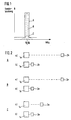
- Fig. 1 is the maximum allowable transmission power of the Device and the maximum permissible frequency bandwidth a certain carrier frequency by the with pulled out Lines represented curve A shown. While at one low data transfer speed according to the Line B shown in broken lines is a small one Frequency bandwidth occurs and thus the maximum permissible Transmitting power of the terminal, so a large one Data transmission distance possible is according to the dotted line C at high data transmission speed the frequency bandwidth considerably larger and thus only a low transmission power or a low one Data transmission distance possible.
- 2 a terminal device is shown at 1e, that is, a terminal whose transmission power is dependent can be controlled by the data transmission speed, with 1k a conventional terminal without one Control of the transmission power, with 2e a data carrier according to the invention, depending on the data transmission distance with different data transfer speeds communicates, and with 2k a conventional data carrier, its ability to communicate on a single data transfer rate is limited.
- a and B can also carry out the method according to the invention be when conventional media 2k with the invention Terminal devices (A) communicate or conventional Terminals 1k with data carriers according to the invention (B).
- Variant (C) in which an inventive terminal and a can be used according to the invention, a highest possible data transfer speed both at large data transmission distance (a) as with short data transmission distance (b) can be achieved.
Landscapes
- Engineering & Computer Science (AREA)
- Signal Processing (AREA)
- Computer Networks & Wireless Communication (AREA)
- Quality & Reliability (AREA)
- Artificial Intelligence (AREA)
- Computer Vision & Pattern Recognition (AREA)
- Physics & Mathematics (AREA)
- General Physics & Mathematics (AREA)
- Theoretical Computer Science (AREA)
- Near-Field Transmission Systems (AREA)
- Bidirectional Digital Transmission (AREA)
- Communication Control (AREA)
Claims (5)
- Procédé de communication bidirectionnelle entre des supports de données fonctionnant sans contact et des postes terminaux qui sont pourvus de dispositifs d'émission d'ondes électromagnétiques pour réaliser un couplage électromagnétique non galvanique avec les supports de données, caractérisé en ce que la vitesse de transmission de données est déterminée en fonction de la distance de transmission de données à surmonter, par une étape de communication additionnelle au début de la transmission de données et en ce que la puissance d'émission du poste terminal est modifiée par étapes en fonction de la vitesse de transmission des données.
- Procédé selon la revendication 1, caractérisé en ce que l'étape de communication additionnelle est constituée de telle sorte qu'avant le début de la communication, le poste terminal émet un modèle de signal servant d'indicatif pour la vitesse respective de transmission de données.
- Procédé selon la revendication 2, caractérisé en ce que le modèle de signal servant d'indicatif pour la vitesse respective de transmission de données est modulé en amplitude et/ou en phase.
- Procédé selon la revendication 1, caractérisé en ce que la modification de la puissance d'émission du poste terminal a lieu en deux étapes pour une distance de transmission de données faible et pour une distance plus importante, respectivement.
- Dispositif de mise en oeuvre du procédé selon l'une des revendications 1 à 4, caractérisé en ce que pour une vitesse de transmission de données dépendant de sdistance de la transmission de données, le poste terminal est pourvu d'une commande pour déterminer la vitesse de transmission de données correspondant à la distance de transmission de données à surmonter par une étape de communication additionnelle au début de la transmission de données et pour modifier par étapes sa puissance d'émission en fonction de la vitesse de transmission de données, et en ce que le support de données est réalisé en fonction de la distance de transmission de données pour la communication avec différentes vitesses de transmission de données.
Applications Claiming Priority (3)
| Application Number | Priority Date | Filing Date | Title |
|---|---|---|---|
| DE19827691 | 1998-06-22 | ||
| DE19827691A DE19827691C1 (de) | 1998-06-22 | 1998-06-22 | Verfahren zur Kommunikation zwischen berührungslos arbeitenden Datenträgern und Endgeräten |
| PCT/EP1999/001932 WO1999067734A1 (fr) | 1998-06-22 | 1999-03-22 | Procede de communication entre des supports de donnees fonctionnant sans contact et des terminaux |
Publications (2)
| Publication Number | Publication Date |
|---|---|
| EP1090370A1 EP1090370A1 (fr) | 2001-04-11 |
| EP1090370B1 true EP1090370B1 (fr) | 2002-08-28 |
Family
ID=7871606
Family Applications (1)
| Application Number | Title | Priority Date | Filing Date |
|---|---|---|---|
| EP99917835A Expired - Lifetime EP1090370B1 (fr) | 1998-06-22 | 1999-03-22 | Procede de communication entre des supports de donnees fonctionnant sans contact et des terminaux |
Country Status (6)
| Country | Link |
|---|---|
| EP (1) | EP1090370B1 (fr) |
| JP (1) | JP4414093B2 (fr) |
| AT (1) | ATE223090T1 (fr) |
| CA (1) | CA2335527A1 (fr) |
| DE (2) | DE19827691C1 (fr) |
| WO (1) | WO1999067734A1 (fr) |
Families Citing this family (4)
| Publication number | Priority date | Publication date | Assignee | Title |
|---|---|---|---|---|
| US6963270B1 (en) | 1999-10-27 | 2005-11-08 | Checkpoint Systems, Inc. | Anticollision protocol with fast read request and additional schemes for reading multiple transponders in an RFID system |
| DE10004922A1 (de) * | 2000-02-04 | 2001-08-09 | Giesecke & Devrient Gmbh | Transponder, insbesondere für eine kontaktlose Chipkarte |
| DE10338311B3 (de) * | 2003-08-13 | 2005-02-10 | Siemens Ag | Transponder-Einrichtung und Balisen-Einrichtung |
| JP4823943B2 (ja) * | 2007-03-06 | 2011-11-24 | 均 北吉 | 無線タグ、無線タグリーダ及びパルス符号化鍵検出回路とそれらを用いた無線タグシステム |
Citations (1)
| Publication number | Priority date | Publication date | Assignee | Title |
|---|---|---|---|---|
| GB2208025A (en) * | 1985-04-10 | 1989-02-15 | Gen Electric Co Plc | Transaction system |
Family Cites Families (6)
| Publication number | Priority date | Publication date | Assignee | Title |
|---|---|---|---|---|
| US4411004A (en) * | 1980-06-27 | 1983-10-18 | Rolm Corporation | Inductively coupled sensing circuit and priority system |
| JP2926660B2 (ja) * | 1990-11-30 | 1999-07-28 | 富士通株式会社 | 移動通信事業者システムにおける発端末−着端末間相対距離算定方法 |
| JP3480746B2 (ja) * | 1993-11-11 | 2003-12-22 | 株式会社東芝 | 携帯可能電子装置 |
| JPH0962816A (ja) * | 1994-10-06 | 1997-03-07 | Mitsubishi Electric Corp | 非接触icカードおよびこれを含む非接触icカードシステム |
| DE19715215C1 (de) * | 1997-04-11 | 1998-10-22 | Siemens Ag | Kontaktloses Transpondersystem |
| DE19726335C2 (de) * | 1997-06-20 | 2000-03-02 | Angewandte Digital Elektronik | Chipkarte mit mindestens zwei Spulenanordnungen zur Übertragung von Daten und/oder Energie |
-
1998
- 1998-06-22 DE DE19827691A patent/DE19827691C1/de not_active Revoked
-
1999
- 1999-03-22 DE DE59902477T patent/DE59902477D1/de not_active Expired - Lifetime
- 1999-03-22 EP EP99917835A patent/EP1090370B1/fr not_active Expired - Lifetime
- 1999-03-22 JP JP2000556327A patent/JP4414093B2/ja not_active Expired - Fee Related
- 1999-03-22 CA CA002335527A patent/CA2335527A1/fr not_active Abandoned
- 1999-03-22 WO PCT/EP1999/001932 patent/WO1999067734A1/fr not_active Ceased
- 1999-03-22 AT AT99917835T patent/ATE223090T1/de active
Patent Citations (1)
| Publication number | Priority date | Publication date | Assignee | Title |
|---|---|---|---|---|
| GB2208025A (en) * | 1985-04-10 | 1989-02-15 | Gen Electric Co Plc | Transaction system |
Also Published As
| Publication number | Publication date |
|---|---|
| CA2335527A1 (fr) | 1999-12-29 |
| ATE223090T1 (de) | 2002-09-15 |
| DE19827691C1 (de) | 2000-01-13 |
| JP2002519875A (ja) | 2002-07-02 |
| JP4414093B2 (ja) | 2010-02-10 |
| EP1090370A1 (fr) | 2001-04-11 |
| WO1999067734A1 (fr) | 1999-12-29 |
| DE59902477D1 (de) | 2002-10-02 |
Similar Documents
| Publication | Publication Date | Title |
|---|---|---|
| DE69430092T2 (de) | Anordnung zur gleichzeitigen Abfrage vieler tragbarer Funkfrequenz-Kommunikationsgeräte | |
| DE69332198T2 (de) | Bidirektionales-Kommunikationssystem mit Doppelresonanz-Antennenschaltung für RF-Anhänger | |
| EP0590122B1 (fr) | Procede et systeme de transmission de structures serielles de donnees pour systemes d'identification de supports d'information, ainsi que support d'information | |
| DE3779723T2 (de) | Datenspeichervorrichtungen. | |
| DE69631564T2 (de) | Vollduplex moduliertes Rückstrahlungssystem | |
| DD269478A5 (de) | Elektronisches datenverarbeitungssystem | |
| EP1861808B1 (fr) | Procede de transmission de donnees et lecteur d'identification par radiofrequence (rfid) equipe d'une bobine et d'un circuit de regulation pour une suppression de champ a l'exterieur de la zone de communication | |
| DE3918052C1 (fr) | ||
| DE10224284A1 (de) | Nutzungsberechtigungskontrollverfahren | |
| DE60303824T2 (de) | Inventurverfahren für transponder mittels einer kommunikationsstation | |
| DE69621176T2 (de) | Kontaktlose IC-Karte und System dafür | |
| DE4225800C1 (de) | Antwortgerät für eine Informationsübertragungseinrichtung | |
| DE19923634A1 (de) | Sende- und Empfangseinrichtung | |
| DE10050878B4 (de) | Verfahren zur Übertragung von mehreren Informationssymbolen | |
| EP1090370B1 (fr) | Procede de communication entre des supports de donnees fonctionnant sans contact et des terminaux | |
| EP1587023A1 (fr) | Procédé de communication de données entre une station de base et un transpondeur | |
| DE69326200T2 (de) | Störunempfindliches Hochfrequenzidentifizierungssystem mit grossem Erkennungsbereich | |
| DE10246668A1 (de) | Zutrittskontrollsystem und Verfahren zum Betrieb eines solchen Zutrittskontrollsystemes | |
| DE69614812T2 (de) | Verfahren zur Verwaltung gleichzeitiger Zugriffe und Gerät zur Durchführung dieses Verfahrens | |
| EP0793191A1 (fr) | Appareil pour la programmation d'une station terrestre | |
| DE60318535T2 (de) | Anordnung zur drahtlosen Informationsübertragung und Kommunikationssystem, das diese Anordnung umfasst | |
| DE102008007842B3 (de) | Synchronisation der Kommunikation zwischen Identifikationsgeber und Fahrzeugstation einer Zugangsvorrichtung | |
| EP0669591B1 (fr) | Système de transmission de données sans contact | |
| DE4110683A1 (de) | Hochfrequenz-sendeeinheit in kleinstbauweise | |
| DE19715215C1 (de) | Kontaktloses Transpondersystem |
Legal Events
| Date | Code | Title | Description |
|---|---|---|---|
| PUAI | Public reference made under article 153(3) epc to a published international application that has entered the european phase |
Free format text: ORIGINAL CODE: 0009012 |
|
| 17P | Request for examination filed |
Effective date: 20001130 |
|
| AK | Designated contracting states |
Kind code of ref document: A1 Designated state(s): AT CH DE FR IT LI SE |
|
| 17Q | First examination report despatched |
Effective date: 20010418 |
|
| GRAG | Despatch of communication of intention to grant |
Free format text: ORIGINAL CODE: EPIDOS AGRA |
|
| GRAG | Despatch of communication of intention to grant |
Free format text: ORIGINAL CODE: EPIDOS AGRA |
|
| GRAH | Despatch of communication of intention to grant a patent |
Free format text: ORIGINAL CODE: EPIDOS IGRA |
|
| GRAH | Despatch of communication of intention to grant a patent |
Free format text: ORIGINAL CODE: EPIDOS IGRA |
|
| GRAA | (expected) grant |
Free format text: ORIGINAL CODE: 0009210 |
|
| AK | Designated contracting states |
Kind code of ref document: B1 Designated state(s): AT CH DE FR IT LI SE |
|
| REF | Corresponds to: |
Ref document number: 223090 Country of ref document: AT Date of ref document: 20020915 Kind code of ref document: T |
|
| REG | Reference to a national code |
Ref country code: CH Ref legal event code: EP |
|
| REF | Corresponds to: |
Ref document number: 59902477 Country of ref document: DE Date of ref document: 20021002 |
|
| REG | Reference to a national code |
Ref country code: CH Ref legal event code: NV Representative=s name: KELLER & PARTNER PATENTANWAELTE AG |
|
| ET | Fr: translation filed | ||
| PLBE | No opposition filed within time limit |
Free format text: ORIGINAL CODE: 0009261 |
|
| STAA | Information on the status of an ep patent application or granted ep patent |
Free format text: STATUS: NO OPPOSITION FILED WITHIN TIME LIMIT |
|
| 26N | No opposition filed |
Effective date: 20030530 |
|
| REG | Reference to a national code |
Ref country code: CH Ref legal event code: PCAR Free format text: NEW ADDRESS: EIGERSTRASSE 2 POSTFACH, 3000 BERN 14 (CH) |
|
| REG | Reference to a national code |
Ref country code: FR Ref legal event code: PLFP Year of fee payment: 18 |
|
| REG | Reference to a national code |
Ref country code: FR Ref legal event code: PLFP Year of fee payment: 19 |
|
| PGFP | Annual fee paid to national office [announced via postgrant information from national office to epo] |
Ref country code: DE Payment date: 20170322 Year of fee payment: 19 Ref country code: SE Payment date: 20170321 Year of fee payment: 19 Ref country code: FR Payment date: 20170322 Year of fee payment: 19 Ref country code: CH Payment date: 20170322 Year of fee payment: 19 |
|
| PGFP | Annual fee paid to national office [announced via postgrant information from national office to epo] |
Ref country code: AT Payment date: 20170322 Year of fee payment: 19 |
|
| PGFP | Annual fee paid to national office [announced via postgrant information from national office to epo] |
Ref country code: IT Payment date: 20170323 Year of fee payment: 19 |
|
| REG | Reference to a national code |
Ref country code: DE Ref legal event code: R119 Ref document number: 59902477 Country of ref document: DE |
|
| PG25 | Lapsed in a contracting state [announced via postgrant information from national office to epo] |
Ref country code: SE Free format text: LAPSE BECAUSE OF NON-PAYMENT OF DUE FEES Effective date: 20180323 |
|
| REG | Reference to a national code |
Ref country code: CH Ref legal event code: PL |
|
| REG | Reference to a national code |
Ref country code: AT Ref legal event code: MM01 Ref document number: 223090 Country of ref document: AT Kind code of ref document: T Effective date: 20180322 |
|
| PG25 | Lapsed in a contracting state [announced via postgrant information from national office to epo] |
Ref country code: DE Free format text: LAPSE BECAUSE OF NON-PAYMENT OF DUE FEES Effective date: 20181002 Ref country code: AT Free format text: LAPSE BECAUSE OF NON-PAYMENT OF DUE FEES Effective date: 20180322 |
|
| PG25 | Lapsed in a contracting state [announced via postgrant information from national office to epo] |
Ref country code: CH Free format text: LAPSE BECAUSE OF NON-PAYMENT OF DUE FEES Effective date: 20180331 Ref country code: IT Free format text: LAPSE BECAUSE OF NON-PAYMENT OF DUE FEES Effective date: 20180322 Ref country code: LI Free format text: LAPSE BECAUSE OF NON-PAYMENT OF DUE FEES Effective date: 20180331 |
|
| PG25 | Lapsed in a contracting state [announced via postgrant information from national office to epo] |
Ref country code: FR Free format text: LAPSE BECAUSE OF NON-PAYMENT OF DUE FEES Effective date: 20180331 |