EP1090708A2 - Schweisskopf für eine Bandumreifungsmaschine - Google Patents
Schweisskopf für eine Bandumreifungsmaschine Download PDFInfo
- Publication number
- EP1090708A2 EP1090708A2 EP00120429A EP00120429A EP1090708A2 EP 1090708 A2 EP1090708 A2 EP 1090708A2 EP 00120429 A EP00120429 A EP 00120429A EP 00120429 A EP00120429 A EP 00120429A EP 1090708 A2 EP1090708 A2 EP 1090708A2
- Authority
- EP
- European Patent Office
- Prior art keywords
- welding
- welding head
- laser
- welded
- band
- Prior art date
- Legal status (The legal status is an assumption and is not a legal conclusion. Google has not performed a legal analysis and makes no representation as to the accuracy of the status listed.)
- Withdrawn
Links
Images

Classifications
-
- B—PERFORMING OPERATIONS; TRANSPORTING
- B29—WORKING OF PLASTICS; WORKING OF SUBSTANCES IN A PLASTIC STATE IN GENERAL
- B29C—SHAPING OR JOINING OF PLASTICS; SHAPING OF MATERIAL IN A PLASTIC STATE, NOT OTHERWISE PROVIDED FOR; AFTER-TREATMENT OF THE SHAPED PRODUCTS, e.g. REPAIRING
- B29C65/00—Joining or sealing of preformed parts, e.g. welding of plastics materials; Apparatus therefor
- B29C65/02—Joining or sealing of preformed parts, e.g. welding of plastics materials; Apparatus therefor by heating, with or without pressure
- B29C65/14—Joining or sealing of preformed parts, e.g. welding of plastics materials; Apparatus therefor by heating, with or without pressure using wave energy, i.e. electromagnetic radiation, or particle radiation
- B29C65/16—Laser beams
- B29C65/1629—Laser beams characterised by the way of heating the interface
- B29C65/1664—Laser beams characterised by the way of heating the interface making use of several radiators
-
- B—PERFORMING OPERATIONS; TRANSPORTING
- B23—MACHINE TOOLS; METAL-WORKING NOT OTHERWISE PROVIDED FOR
- B23K—SOLDERING OR UNSOLDERING; WELDING; CLADDING OR PLATING BY SOLDERING OR WELDING; CUTTING BY APPLYING HEAT LOCALLY, e.g. FLAME CUTTING; WORKING BY LASER BEAM
- B23K26/00—Working by laser beam, e.g. welding, cutting or boring
- B23K26/02—Positioning or observing the workpiece, e.g. with respect to the point of impact; Aligning, aiming or focusing the laser beam
- B23K26/06—Shaping the laser beam, e.g. by masks or multi-focusing
- B23K26/0604—Shaping the laser beam, e.g. by masks or multi-focusing by a combination of beams
-
- B—PERFORMING OPERATIONS; TRANSPORTING
- B23—MACHINE TOOLS; METAL-WORKING NOT OTHERWISE PROVIDED FOR
- B23K—SOLDERING OR UNSOLDERING; WELDING; CLADDING OR PLATING BY SOLDERING OR WELDING; CUTTING BY APPLYING HEAT LOCALLY, e.g. FLAME CUTTING; WORKING BY LASER BEAM
- B23K26/00—Working by laser beam, e.g. welding, cutting or boring
- B23K26/08—Devices involving relative movement between laser beam and workpiece
- B23K26/10—Devices involving relative movement between laser beam and workpiece using a fixed support, i.e. involving moving the laser beam
-
- B—PERFORMING OPERATIONS; TRANSPORTING
- B29—WORKING OF PLASTICS; WORKING OF SUBSTANCES IN A PLASTIC STATE IN GENERAL
- B29C—SHAPING OR JOINING OF PLASTICS; SHAPING OF MATERIAL IN A PLASTIC STATE, NOT OTHERWISE PROVIDED FOR; AFTER-TREATMENT OF THE SHAPED PRODUCTS, e.g. REPAIRING
- B29C65/00—Joining or sealing of preformed parts, e.g. welding of plastics materials; Apparatus therefor
- B29C65/02—Joining or sealing of preformed parts, e.g. welding of plastics materials; Apparatus therefor by heating, with or without pressure
- B29C65/14—Joining or sealing of preformed parts, e.g. welding of plastics materials; Apparatus therefor by heating, with or without pressure using wave energy, i.e. electromagnetic radiation, or particle radiation
- B29C65/16—Laser beams
- B29C65/1629—Laser beams characterised by the way of heating the interface
- B29C65/1635—Laser beams characterised by the way of heating the interface at least passing through one of the parts to be joined, i.e. laser transmission welding
-
- B—PERFORMING OPERATIONS; TRANSPORTING
- B29—WORKING OF PLASTICS; WORKING OF SUBSTANCES IN A PLASTIC STATE IN GENERAL
- B29C—SHAPING OR JOINING OF PLASTICS; SHAPING OF MATERIAL IN A PLASTIC STATE, NOT OTHERWISE PROVIDED FOR; AFTER-TREATMENT OF THE SHAPED PRODUCTS, e.g. REPAIRING
- B29C65/00—Joining or sealing of preformed parts, e.g. welding of plastics materials; Apparatus therefor
- B29C65/02—Joining or sealing of preformed parts, e.g. welding of plastics materials; Apparatus therefor by heating, with or without pressure
- B29C65/14—Joining or sealing of preformed parts, e.g. welding of plastics materials; Apparatus therefor by heating, with or without pressure using wave energy, i.e. electromagnetic radiation, or particle radiation
- B29C65/16—Laser beams
- B29C65/1629—Laser beams characterised by the way of heating the interface
- B29C65/1674—Laser beams characterised by the way of heating the interface making use of laser diodes
-
- B—PERFORMING OPERATIONS; TRANSPORTING
- B29—WORKING OF PLASTICS; WORKING OF SUBSTANCES IN A PLASTIC STATE IN GENERAL
- B29C—SHAPING OR JOINING OF PLASTICS; SHAPING OF MATERIAL IN A PLASTIC STATE, NOT OTHERWISE PROVIDED FOR; AFTER-TREATMENT OF THE SHAPED PRODUCTS, e.g. REPAIRING
- B29C66/00—General aspects of processes or apparatus for joining preformed parts
- B29C66/01—General aspects dealing with the joint area or with the area to be joined
- B29C66/05—Particular design of joint configurations
- B29C66/10—Particular design of joint configurations particular design of the joint cross-sections
- B29C66/11—Joint cross-sections comprising a single joint-segment, i.e. one of the parts to be joined comprising a single joint-segment in the joint cross-section
- B29C66/112—Single lapped joints
- B29C66/1122—Single lap to lap joints, i.e. overlap joints
-
- B—PERFORMING OPERATIONS; TRANSPORTING
- B29—WORKING OF PLASTICS; WORKING OF SUBSTANCES IN A PLASTIC STATE IN GENERAL
- B29C—SHAPING OR JOINING OF PLASTICS; SHAPING OF MATERIAL IN A PLASTIC STATE, NOT OTHERWISE PROVIDED FOR; AFTER-TREATMENT OF THE SHAPED PRODUCTS, e.g. REPAIRING
- B29C66/00—General aspects of processes or apparatus for joining preformed parts
- B29C66/01—General aspects dealing with the joint area or with the area to be joined
- B29C66/05—Particular design of joint configurations
- B29C66/20—Particular design of joint configurations particular design of the joint lines, e.g. of the weld lines
- B29C66/21—Particular design of joint configurations particular design of the joint lines, e.g. of the weld lines said joint lines being formed by a single dot or dash or by several dots or dashes, i.e. spot joining or spot welding
-
- B—PERFORMING OPERATIONS; TRANSPORTING
- B29—WORKING OF PLASTICS; WORKING OF SUBSTANCES IN A PLASTIC STATE IN GENERAL
- B29C—SHAPING OR JOINING OF PLASTICS; SHAPING OF MATERIAL IN A PLASTIC STATE, NOT OTHERWISE PROVIDED FOR; AFTER-TREATMENT OF THE SHAPED PRODUCTS, e.g. REPAIRING
- B29C66/00—General aspects of processes or apparatus for joining preformed parts
- B29C66/40—General aspects of joining substantially flat articles, e.g. plates, sheets or web-like materials; Making flat seams in tubular or hollow articles; Joining single elements to substantially flat surfaces
- B29C66/41—Joining substantially flat articles ; Making flat seams in tubular or hollow articles
- B29C66/43—Joining a relatively small portion of the surface of said articles
- B29C66/432—Joining a relatively small portion of the surface of said articles for making tubular articles or closed loops, e.g. by joining several sheets ; for making hollow articles or hollow preforms
- B29C66/4322—Joining a relatively small portion of the surface of said articles for making tubular articles or closed loops, e.g. by joining several sheets ; for making hollow articles or hollow preforms by joining a single sheet to itself
-
- B—PERFORMING OPERATIONS; TRANSPORTING
- B29—WORKING OF PLASTICS; WORKING OF SUBSTANCES IN A PLASTIC STATE IN GENERAL
- B29C—SHAPING OR JOINING OF PLASTICS; SHAPING OF MATERIAL IN A PLASTIC STATE, NOT OTHERWISE PROVIDED FOR; AFTER-TREATMENT OF THE SHAPED PRODUCTS, e.g. REPAIRING
- B29C66/00—General aspects of processes or apparatus for joining preformed parts
- B29C66/40—General aspects of joining substantially flat articles, e.g. plates, sheets or web-like materials; Making flat seams in tubular or hollow articles; Joining single elements to substantially flat surfaces
- B29C66/41—Joining substantially flat articles ; Making flat seams in tubular or hollow articles
- B29C66/43—Joining a relatively small portion of the surface of said articles
- B29C66/432—Joining a relatively small portion of the surface of said articles for making tubular articles or closed loops, e.g. by joining several sheets ; for making hollow articles or hollow preforms
- B29C66/4324—Joining a relatively small portion of the surface of said articles for making tubular articles or closed loops, e.g. by joining several sheets ; for making hollow articles or hollow preforms for making closed loops, e.g. belts
-
- B—PERFORMING OPERATIONS; TRANSPORTING
- B29—WORKING OF PLASTICS; WORKING OF SUBSTANCES IN A PLASTIC STATE IN GENERAL
- B29C—SHAPING OR JOINING OF PLASTICS; SHAPING OF MATERIAL IN A PLASTIC STATE, NOT OTHERWISE PROVIDED FOR; AFTER-TREATMENT OF THE SHAPED PRODUCTS, e.g. REPAIRING
- B29C66/00—General aspects of processes or apparatus for joining preformed parts
- B29C66/40—General aspects of joining substantially flat articles, e.g. plates, sheets or web-like materials; Making flat seams in tubular or hollow articles; Joining single elements to substantially flat surfaces
- B29C66/49—Internally supporting the, e.g. tubular, article during joining
-
- B—PERFORMING OPERATIONS; TRANSPORTING
- B29—WORKING OF PLASTICS; WORKING OF SUBSTANCES IN A PLASTIC STATE IN GENERAL
- B29C—SHAPING OR JOINING OF PLASTICS; SHAPING OF MATERIAL IN A PLASTIC STATE, NOT OTHERWISE PROVIDED FOR; AFTER-TREATMENT OF THE SHAPED PRODUCTS, e.g. REPAIRING
- B29C66/00—General aspects of processes or apparatus for joining preformed parts
- B29C66/80—General aspects of machine operations or constructions and parts thereof
-
- B—PERFORMING OPERATIONS; TRANSPORTING
- B29—WORKING OF PLASTICS; WORKING OF SUBSTANCES IN A PLASTIC STATE IN GENERAL
- B29C—SHAPING OR JOINING OF PLASTICS; SHAPING OF MATERIAL IN A PLASTIC STATE, NOT OTHERWISE PROVIDED FOR; AFTER-TREATMENT OF THE SHAPED PRODUCTS, e.g. REPAIRING
- B29C66/00—General aspects of processes or apparatus for joining preformed parts
- B29C66/80—General aspects of machine operations or constructions and parts thereof
- B29C66/81—General aspects of the pressing elements, i.e. the elements applying pressure on the parts to be joined in the area to be joined, e.g. the welding jaws or clamps
- B29C66/814—General aspects of the pressing elements, i.e. the elements applying pressure on the parts to be joined in the area to be joined, e.g. the welding jaws or clamps characterised by the design of the pressing elements, e.g. of the welding jaws or clamps
- B29C66/8141—General aspects of the pressing elements, i.e. the elements applying pressure on the parts to be joined in the area to be joined, e.g. the welding jaws or clamps characterised by the design of the pressing elements, e.g. of the welding jaws or clamps characterised by the surface geometry of the part of the pressing elements, e.g. welding jaws or clamps, coming into contact with the parts to be joined
- B29C66/81411—General aspects of the pressing elements, i.e. the elements applying pressure on the parts to be joined in the area to be joined, e.g. the welding jaws or clamps characterised by the design of the pressing elements, e.g. of the welding jaws or clamps characterised by the surface geometry of the part of the pressing elements, e.g. welding jaws or clamps, coming into contact with the parts to be joined characterised by its cross-section, e.g. transversal or longitudinal, being non-flat
- B29C66/81425—General aspects of the pressing elements, i.e. the elements applying pressure on the parts to be joined in the area to be joined, e.g. the welding jaws or clamps characterised by the design of the pressing elements, e.g. of the welding jaws or clamps characterised by the surface geometry of the part of the pressing elements, e.g. welding jaws or clamps, coming into contact with the parts to be joined characterised by its cross-section, e.g. transversal or longitudinal, being non-flat being stepped, e.g. comprising a shoulder
-
- B—PERFORMING OPERATIONS; TRANSPORTING
- B29—WORKING OF PLASTICS; WORKING OF SUBSTANCES IN A PLASTIC STATE IN GENERAL
- B29C—SHAPING OR JOINING OF PLASTICS; SHAPING OF MATERIAL IN A PLASTIC STATE, NOT OTHERWISE PROVIDED FOR; AFTER-TREATMENT OF THE SHAPED PRODUCTS, e.g. REPAIRING
- B29C66/00—General aspects of processes or apparatus for joining preformed parts
- B29C66/80—General aspects of machine operations or constructions and parts thereof
- B29C66/83—General aspects of machine operations or constructions and parts thereof characterised by the movement of the joining or pressing tools
- B29C66/832—Reciprocating joining or pressing tools
- B29C66/8322—Joining or pressing tools reciprocating along one axis
-
- B—PERFORMING OPERATIONS; TRANSPORTING
- B65—CONVEYING; PACKING; STORING; HANDLING THIN OR FILAMENTARY MATERIAL
- B65B—MACHINES, APPARATUS OR DEVICES FOR, OR METHODS OF, PACKAGING ARTICLES OR MATERIALS; UNPACKING
- B65B13/00—Bundling articles
- B65B13/18—Details of, or auxiliary devices used in, bundling machines or bundling tools
- B65B13/24—Securing ends of binding material
- B65B13/32—Securing ends of binding material by welding, soldering, or heat-sealing; by applying adhesive
-
- B—PERFORMING OPERATIONS; TRANSPORTING
- B23—MACHINE TOOLS; METAL-WORKING NOT OTHERWISE PROVIDED FOR
- B23K—SOLDERING OR UNSOLDERING; WELDING; CLADDING OR PLATING BY SOLDERING OR WELDING; CUTTING BY APPLYING HEAT LOCALLY, e.g. FLAME CUTTING; WORKING BY LASER BEAM
- B23K2101/00—Articles made by soldering, welding or cutting
- B23K2101/04—Tubular or hollow articles
-
- B—PERFORMING OPERATIONS; TRANSPORTING
- B29—WORKING OF PLASTICS; WORKING OF SUBSTANCES IN A PLASTIC STATE IN GENERAL
- B29C—SHAPING OR JOINING OF PLASTICS; SHAPING OF MATERIAL IN A PLASTIC STATE, NOT OTHERWISE PROVIDED FOR; AFTER-TREATMENT OF THE SHAPED PRODUCTS, e.g. REPAIRING
- B29C65/00—Joining or sealing of preformed parts, e.g. welding of plastics materials; Apparatus therefor
- B29C65/02—Joining or sealing of preformed parts, e.g. welding of plastics materials; Apparatus therefor by heating, with or without pressure
- B29C65/14—Joining or sealing of preformed parts, e.g. welding of plastics materials; Apparatus therefor by heating, with or without pressure using wave energy, i.e. electromagnetic radiation, or particle radiation
- B29C65/16—Laser beams
- B29C65/1629—Laser beams characterised by the way of heating the interface
- B29C65/1664—Laser beams characterised by the way of heating the interface making use of several radiators
- B29C65/1667—Laser beams characterised by the way of heating the interface making use of several radiators at the same time, i.e. simultaneous laser welding
-
- B—PERFORMING OPERATIONS; TRANSPORTING
- B29—WORKING OF PLASTICS; WORKING OF SUBSTANCES IN A PLASTIC STATE IN GENERAL
- B29C—SHAPING OR JOINING OF PLASTICS; SHAPING OF MATERIAL IN A PLASTIC STATE, NOT OTHERWISE PROVIDED FOR; AFTER-TREATMENT OF THE SHAPED PRODUCTS, e.g. REPAIRING
- B29C65/00—Joining or sealing of preformed parts, e.g. welding of plastics materials; Apparatus therefor
- B29C65/02—Joining or sealing of preformed parts, e.g. welding of plastics materials; Apparatus therefor by heating, with or without pressure
- B29C65/14—Joining or sealing of preformed parts, e.g. welding of plastics materials; Apparatus therefor by heating, with or without pressure using wave energy, i.e. electromagnetic radiation, or particle radiation
- B29C65/16—Laser beams
- B29C65/1687—Laser beams making use of light guides
Definitions
- the invention relates to a welding head for a strapping machine with the features specified in the preamble of claim 1.
- Such a welding head is for example from DE 297 16 897 U1 known.
- Such welding heads are with heated welding tongues common in the field of strapping machines and others also used by the applicant for years.
- a bearing housing In a bearing housing are several slidably guided transversely to the band plane, in Belt running direction of clamping jaws arranged one behind the other, that serve to fix and apply the strapping.
- the Clamping jaws are in their respective via a cam disc control Position spent.
- the welding head also has a parallel to the strapping plane on the bearing housing and pressure plate guided to be displaceable transversely to the tape running direction on the top as a counter-holder when the tape start is applied and the band section overlapping therewith during welding on.
- a welding tongue between those to be welded Tape layers can be inserted, is guided parallel to the pressure plate on the bearing housing.
- the invention has for its object the welding device a Generic welding head to improve so that a more compact Formation of the head itself and reliable strapping welding with reduced mechanical and control technology Effort in the manufacture and operation of the welding head can be achieved.
- the invention works with electromagnetic radiation in Form of laser beams. This completely eliminates the need for one - As discussed - expensive to spend between the belt sections mechanical part. Rather, the tape sections can immediately after the Strapping and severing the strapping strap from the strap stock the laser radiation is applied, melted and by the pressing action the jaws are permanently connected.
- the laser radiation as such can, according to preferred embodiments the invention, for example, in the jaws or - with appropriate Space - arranged between such jaws Laser diodes are generated.
- the strapping machine and fiber optic fiber optic cables the laser radiation to the strip sections to be welded in Head. This can be through the jaws or, for example via the pressure plate serving as a counterhold.
- bearing housing 2 designed as a cast block as backbone for all functional parts on.
- the bearing housing 2 consists of a not shown Base plate with which the bearing housing 2 e.g. on a frame strut of the Machine frame of the strapping machine is flanged.
- Base plate extend two integrally molded, lateral supports 5, 6 upwards, on which the housing body 7 is formed in an integral manner is. The latter carries the appropriate mounts and fastenings for the other functional parts of the welding head, as described in more detail becomes.
- the first Clamping jaws 12 serve to fix the leading beginning section 3 of a strapping tape shot into the strapping machine 4 in the welding head 1 during the withdrawal to tighten the Band 4 and during its welding.
- the beginning of the tape 3 is by a corrugated clamping surface 15 on the basic width of the jaw 12 narrowed head 16 fixed.
- a window 17 is also provided, through which the strapping machine entering band run runs through.
- the second clamping jaw 13 serves to fix the beginning of the band overlapping band section during the welding of these two Band areas.
- This jaw 13 also has a narrow head 18 provided with corrugated clamping surface 19.
- the third jaw 14 is between the first and second jaws 12, 13 arranged and serves for the joint action of the The beginning of the tape and the overlapping tape section during the Welding these two parts of the tape. Because the interaction of the three Clamping jaws 12, 13, 14 when shooting in, pulling back, welding and cutting off the loop formed around a material to be strapped analogously prior art is a detailed description of this Operations not necessary.
- Fig. 1 also shows a printing plate unit 30, which corresponds to a corresponding Flange surface 31 built on the top of the housing body 7 becomes. A more detailed description follows later.
- the structure of the jaws 12, 13, 14 and their guideways 9, 10, 11 can also be seen in FIG. 1. So the guideways 9, 10, 11 each by the cross section corresponding to that of the clamping jaws 12, 13, 14 Recesses in the housing body 7 formed by one piece integrally formed webs 20, 21 are separated from each other. In the the jaws 12, 13, 14 are each laterally flanking surfaces flat lubricant pockets 22 molded to a flawless and low-friction running of the jaws 12, 13, 14 in the guideways 9, 10, 11 to ensure.
- the outer side 8 of the housing body is aligned 7 and the corresponding side surfaces of the jaws 12, 13, 14. Now the housing body 7 is closed with these guideways 9, 10, 11 and the jaws 12, 13, 14 by a side to the outside 8 screwed on housing cover (not shown).
- FIG. 1 also shows one at the upper end of the middle jaw 14 above the corresponding web 20 in a lateral recess 23 seated knife block 24, which on the side facing him the first Clamping jaw 12 with a cutting surface 25 and a sliding surface 26 supports.
- the knife block 24 is in the direction of the first jaw 12 acted upon by a helical compression spring, not shown, which in two blind holes in the jaws 14 or in the knife block 24.
- the cutting surface 25 acts with the window 17 in the first clamping jaw 12 together and separates from with a corresponding relative movement Jaws 12 and 14 (with knife block 24) to each other through the Window 17 running strapping 4 through.
- the structure of the printing plate unit 30 is to be explained with reference to FIG. 1.
- the actual pressure plate 32 is basically parallel to the strapping level and slidably guided transversely to the tape running direction and on the Top of the welding head as a counterholder when the The beginning of the tape and the overlapping tape section during the Welding arranged.
- the ability to move across the belt running direction is to be provided after welding the tape in its taut condition the strapping to remove the to release strapped good. Due to the transverse shift, the pressure plate thereby from their position between strapping material and strapping loop pulled out.
- the sliding guide of the pressure plate 32 is carried out by a to the pressure plate 32 integrally molded, essentially plate-shaped guide part 33, the top with recesses 34 to save weight is provided. This has a beneficial effect on accelerating the Pressure plate 32 forces occurring during the lateral displacement and moments out. It can reduce wear and tear be achieved.
- a guide carriage (not shown) by means of the Screws 35 attached to the lower surface of the guide part 33 each forms a guide groove open to the outside.
- these guide grooves grip webs from the outside in the manner of a tongue and groove connection one on the bearing housing 2 on the flange surface 31 of the housing body 7 by means of screws 36 mounted guide bracket 37.
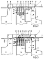
- the laser diodes 41 have one converging radiation pattern with a focal length that is about the distance between the laser diodes 41 and the contact area between corresponds to the two band sections 3, 38.
- the laser energy is in the contact plane between the two band sections 3, 38 bundled where the band material warmed, melted and under the simultaneous pressure of the jaw 14 a fused connection between the two sections 3, 38 is formed.
- the type, wavelength, energy density and radiation characteristics the laser diodes is practical and in particular to be selected according to the type and quality of tape and can vary widely. The right choice can be determined by simple experiments.
- Fig. 3 shows a further embodiment of the invention, in which the laser beams not generated directly in the jaws 14, but by fiber optic Optical fiber cable 46 from one indicated schematically in FIG. 1 Supply laser 47 can be introduced.
- the fiber optic cables run for this 46 in the jaws 14 and are via feed-through channels 44 ' pulled up to the clamping surface 42.
- At the ends of the fiber optic cables 46 are converging lenses 48 as optical elements for bundling the from the respective fiber optic cable 46 emerging laser beam to be welded Band sections 3, 38 are provided.
- the bundling characteristics can be chosen so that not too sharp focus, but more a bundling area penetrating the volume of the strapping band is achieved, as in Fig. 3 by the larger compared to Fig. 2 hatched areas in the two band sections 3, 38 is indicated.
- Realized laser radiation for the welding process be that a laser beam is brought over the pressure plate 32.
- Another fiber optic cable 46 'runs in a feed-through channel 44 '' in the pressure plate 32, taking suitable measures for deflection of the laser beam emerging from the cable 46 'into the welding plane are provided in the form of deflecting mirrors 51.
- the middle jaw 14 moves with the knife block 24 upwards, whereby on the one hand the band end section 38 from Tape supply is cut off.
- the clamping surface acts 42 of the clamping jaw 14, the band sections 3, 38 to be welded, the laser welding device 40 being activated at the same time.
- Light energy is introduced into sections 3, 38 which heat up, melt and by the pressure of the jaw 14 against the Weld the pressure plate 32.
- all jaws 12, 13, 14 down and the pressure plate 32 moved away to the side so that the welded strap loop is released and the strapped stack can be transported away.
Landscapes
- Engineering & Computer Science (AREA)
- Mechanical Engineering (AREA)
- Physics & Mathematics (AREA)
- Optics & Photonics (AREA)
- Health & Medical Sciences (AREA)
- Electromagnetism (AREA)
- Toxicology (AREA)
- Plasma & Fusion (AREA)
- Microelectronics & Electronic Packaging (AREA)
- Basic Packing Technique (AREA)
- Lining Or Joining Of Plastics Or The Like (AREA)
- Laser Beam Processing (AREA)
Abstract
- einem Lagergehäuse (2),
- mehreren Klemmbacken (12, 13, 14) zur Fixierung und Beaufschlagung des Bandanfangs (3) und des damit überlappenden Bandabschnittes (38) während des Rückzuges und des Verschweißens des Umreifungsbandes (4),
- einer Druckplatte (32) an der Oberseite des Schweißkopfes (1) als Gegenhalter bei der Beaufschlagung des Bandanfangs (3) und des damit überlappenden Bandabschnitts (38) während des Verschweißens, und
- einer Verschweißeinrichtung im Schweißkopf (1) zur Verschweißung des Bandanfangs (3) mit dem damit überlappenden Bandabschnitt (38).
Description
- Fig. 1
- eine ausschnittsweise perspektivische Darstellung eines Schweißkopfes, sowie
- Fig. 2 und 3
- ausschnittsweise Seitenansichten durch Schweißköpfe mit zwei unterschiedlichen Ausführungsformen der Laserschweißeinrichtung.
Claims (9)
- Schweißkopf für eine Bandumreifungsmaschine miteinem Lagergehäuse (2),mehreren Klemmbacken (12, 13, 14) zur Fixierung und Beaufschlagung des Bandanfangs (3) und des damit überlappenden Bandabschnittes (38) während des Rückzuges und des Verschweißens des Umreifungsbandes (4),einer Druckplatte (32) an der Oberseite des Schweißkopfes (1) als Gegenhalter bei der Beaufschlagung des Bandanfangs (3) und des damit überlappenden Bandabschnitts (38) während des Verschweißens, undeiner Verschweißeinrichtung im Schweißkopf (1) zur Verschweißung des Bandanfangs (3) mit dem damit überlappenden Bandabschnitt (38), dadurch gekennzeichnet, daß die Verschweißeinrichtung durch eine im Schweißkopf (1) auf die zu verschweißenden Bandabschnitte (3, 38) einwirkende Laserstrahl-Verschweißeinrichtung (40) gebildet ist.
- Schweißkopf nach Anspruch 1, dadurch gekennzeichnet, daß die Verschweißeinrichtung (40) eine oder mehrere in mindestens einem der Klemmbacken (12, 13, 14) angeordnete Laserdioden (41) aufweist.
- Schweißkopf nach Anspruch 2, dadurch gekennzeichnet, daß die Laserdioden (41) in zu den zu verschweißenden Bandabschnitten (3, 38) hin offenen Lagerkanälen (43) in dem entsprechenden Klemmbacken (14) angeordnet sind.
- Schweißkopf nach einem der Ansprüche 1 bis 3, dadurch gekennzeichnet, daß die Laserschweißeinrichtung (40) durch einen außerhalb der Klemmbacken (12, 13, 14) angeordneten Versorgungslaser (47) gebildet ist, von dem mindestens ein faseroptisches Lichtleiterkabel (46, 46') zur Führung eines Laserstrahls zu den zu verschweißenden Bandabschnitten (3, 38) ausgeht.
- Schweißkopf nach einem der Ansprüche 1 bis 4, dadurch gekennzeichnet, daß die Laserschweißeinrichtung (40) optische Elemente (48) zur Bündelung des Laserstrahles auf die zu verschweißenden Bandabschnitte (3, 38) aufweist.
- Schweißkopf nach Anspruch 2 oder 4, dadurch gekennzeichnet, daß die Versorgungsleitungen (45) der Laserdioden (41) oder die Lichtleiterkabel (46, 46') jeweils in einem Durchführungskanal (44, 44') im zugeordneten Klemmbacken (14) untergebracht sind.
- Schweißkopf nach Anspruch 5 und 6, dadurch gekennzeichnet, daß die optischen Elemente jeweils durch Linsen (48) im Endbereich des jeweiligen Durchführungskanals (44') gebildet sind.
- Schweißkopf mindestens nach Anspruch 6, dadurch gekennzeichnet, daß die Mündungsöffnung (49) des Durchführungskanals (44') zu den zu verschweißenden Bandabschnitten (3, 38) hin durch eine transparente Abdeckung (50) verschlossen ist.
- Schweißkopf nach einem der Ansprüche 1 bis 8, dadurch gekennzeichnet, daß ein Laserstrahl über die Druckplatte (32) an die zu verschweißenden Bandabschnitte (3, 38) herangeführt ist.
Applications Claiming Priority (2)
| Application Number | Priority Date | Filing Date | Title |
|---|---|---|---|
| DE19948880 | 1999-10-08 | ||
| DE1999148880 DE19948880A1 (de) | 1999-10-08 | 1999-10-08 | Schweißkopf für eine Bandumreifungsmaschine |
Publications (2)
| Publication Number | Publication Date |
|---|---|
| EP1090708A2 true EP1090708A2 (de) | 2001-04-11 |
| EP1090708A3 EP1090708A3 (de) | 2002-01-09 |
Family
ID=7925198
Family Applications (1)
| Application Number | Title | Priority Date | Filing Date |
|---|---|---|---|
| EP20000120429 Withdrawn EP1090708A3 (de) | 1999-10-08 | 2000-09-19 | Schweisskopf für eine Bandumreifungsmaschine |
Country Status (3)
| Country | Link |
|---|---|
| US (1) | US6403917B1 (de) |
| EP (1) | EP1090708A3 (de) |
| DE (1) | DE19948880A1 (de) |
Cited By (3)
| Publication number | Priority date | Publication date | Assignee | Title |
|---|---|---|---|---|
| AT12589U1 (de) * | 2010-05-04 | 2012-08-15 | Cyklop Gmbh | Vorrichtung zum umreifen von packstücken mit umreifungsband |
| WO2017129679A1 (en) * | 2016-01-29 | 2017-08-03 | Sund Birsta Ab | Binding machine and method for securing a part of a binding element in a loop around one or more objects |
| CN107697337A (zh) * | 2017-07-06 | 2018-02-16 | 深圳大工人科技有限公司 | Dgr‑vi型激光焊式全自动钢带打捆机 |
Families Citing this family (13)
| Publication number | Priority date | Publication date | Assignee | Title |
|---|---|---|---|---|
| DE10323171B4 (de) * | 2003-05-22 | 2006-07-27 | Helmut Schmetzer | Schweißkopf für eine Bandumreifungsmaschine |
| US20060006155A1 (en) * | 2004-07-08 | 2006-01-12 | Hill Graham E | Device for assembling a banded fuel cell stack |
| EP2243602B1 (de) * | 2009-04-22 | 2013-05-15 | KUKA Roboter GmbH | Verfahren und Vorrichtung zur Regelung eines Manipulators |
| DE102013222427A1 (de) | 2013-11-05 | 2015-05-07 | Krones Aktiengesellschaft | Verfahren und Vorrichtung zur Verschweißung von Umreifungsbändern aus Kunststoff |
| DE102014211849A1 (de) | 2014-06-20 | 2015-12-24 | Krones Aktiengesellschaft | Verfahren und Vorrichtung zur Verbindung von Endbereichen aus Kunststoff bestehender Umreifungsbänder |
| DE102014225880A1 (de) | 2014-12-15 | 2016-06-16 | Krones Aktiengesellschaft | Umreifungskopf und Verfahren zum Umgang mit einem Umreifungsband |
| DE102014225870A1 (de) | 2014-12-15 | 2016-06-16 | Krones Aktiengesellschaft | Umreifungskopf und Verfahren zum Umgang mit einem Umreifungsband |
| US20160304224A1 (en) * | 2015-04-14 | 2016-10-20 | Signode Industrial Group Llc | Dovetail strap cutter in a strap sealing machine |
| EP3363577A1 (de) | 2017-02-17 | 2018-08-22 | Sund Birsta AB | Bindemaschine und verfahren zur sicherung eines teils eines bindungselements in einer schleife um eines oder mehrere objekte |
| EP3363578A1 (de) * | 2017-02-17 | 2018-08-22 | Sund Birsta AB | Bindemaschine und verfahren zur sicherung eines teils eines bindungselements in einer schleife um eines oder mehrere objekte |
| EP3584031A1 (de) | 2018-06-20 | 2019-12-25 | Sund Birsta AB | Umreifungsmaschine und verfahren zum befestigen eines beschichteten metallbandstücks in einer schlaufe um ein oder mehrere objekte |
| CN111390487B (zh) * | 2020-03-27 | 2021-09-17 | 北京丰达汽车部件有限公司 | 一种用于横梁焊接的夹持转台 |
| DE102024002568A1 (de) * | 2024-08-08 | 2024-12-19 | Mercedes-Benz Group AG | Laserschweißgerät zum Schweißen von Kunststoffbauteilen und Verfahren zum Schweißen von Kunststoffbauteilen |
Family Cites Families (14)
| Publication number | Priority date | Publication date | Assignee | Title |
|---|---|---|---|---|
| US3316687A (en) * | 1964-02-06 | 1967-05-02 | Fmc Corp | Strap securing method |
| US3442732A (en) * | 1965-08-13 | 1969-05-06 | Signode Corp | Friction-fusion strap sealing |
| DE1958430A1 (de) * | 1969-11-21 | 1971-05-27 | Dozler Geb Bauscher Elisabeth | Schweisseinrichtung |
| US3749622A (en) * | 1971-11-08 | 1973-07-31 | Ikegai Iron Works Ltd | Method of welding thermoplastic band for use in packing machine as well as apparatus relevant thereto |
| DE2453999A1 (de) * | 1974-11-14 | 1976-05-20 | Brill Ingenieurgesellschaft Mb | Vorrichtung zur herstellung von bandumreifungen |
| DE3805353C1 (en) * | 1988-02-20 | 1989-08-24 | Daimler-Benz Aktiengesellschaft, 7000 Stuttgart, De | Apparatus for the localised heating, in particular welding, of workpieces by means of a focused laser beam |
| DE3842074C2 (de) * | 1988-12-14 | 1997-02-13 | Bosch Gmbh Robert | Aufbringen einer Wickelkopfbandage aus Glasfasern auf den Rotor einer elektrischen Maschine |
| ES2043166T3 (es) * | 1990-04-06 | 1993-12-16 | Thyssen Industrie | Procedimiento para soldar una con otra chapas de acero de espesor diferente o igual - tambien chapas delgadas - mediante soldadura por rayo laser en regimen continuo. |
| DE4233159A1 (de) * | 1992-10-02 | 1994-04-07 | Bwg Bergwerk Walzwerk | Vorrichtung zum Stumpfschweißen von Stoßflächen metallischer Werkstücke, insbesondere gestoßener Bandenden von Metallbändern |
| DE4313270C2 (de) * | 1993-04-23 | 1996-12-19 | Krupp Ag Hoesch Krupp | Verfahren und Vorrichtung zur Herstellung von Verschlüssen an Packstücke umgreifenden Bandeisenumreifungen |
| DE19500086A1 (de) * | 1995-01-04 | 1996-07-11 | Smb Schwede Maschinenbau Gmbh | Vorrichtung zum Umreifen von Packgut mit einem Umreifungsband, insbesondere Querumreifungsmaschine für Zeitschriftenstapel |
| DE19632625A1 (de) * | 1996-08-13 | 1998-02-19 | Rofin Sinar Laser Gmbh | Verfahren und Vorrichtung zum Schweißverbinden zweier Bauteile |
| DE19828244A1 (de) * | 1997-07-22 | 1999-01-28 | Smb Schwede Maschinenbau Gmbh | Bandantriebsvorrichtung für Bandumreifungsmaschinen |
| PT1036239E (pt) * | 1997-12-01 | 2004-01-30 | Colbond Geosynthetics Gmbh | Malha geotextil e estrutura de engenharia civil incluindo uma tal malha geotextil |
-
1999
- 1999-10-08 DE DE1999148880 patent/DE19948880A1/de not_active Withdrawn
-
2000
- 2000-09-19 EP EP20000120429 patent/EP1090708A3/de not_active Withdrawn
- 2000-10-10 US US09/684,324 patent/US6403917B1/en not_active Expired - Fee Related
Cited By (6)
| Publication number | Priority date | Publication date | Assignee | Title |
|---|---|---|---|---|
| AT12589U1 (de) * | 2010-05-04 | 2012-08-15 | Cyklop Gmbh | Vorrichtung zum umreifen von packstücken mit umreifungsband |
| WO2017129679A1 (en) * | 2016-01-29 | 2017-08-03 | Sund Birsta Ab | Binding machine and method for securing a part of a binding element in a loop around one or more objects |
| RU2725330C2 (ru) * | 2016-01-29 | 2020-07-02 | Сунд Бирста Аб | Обвязочная машина и способ крепления части обвязывающего элемента в петле вокруг одного или нескольких объектов |
| TWI706896B (zh) * | 2016-01-29 | 2020-10-11 | 瑞典商 瑞典森德斯有限公司 | 用於將捆紮元件的一部分固定在一圍繞一或多個物件的環圈中之捆紮機與方法 |
| US11332270B2 (en) | 2016-01-29 | 2022-05-17 | Sund Birsta Ab | Binding machine and method for securing a part of a binding element in a loop around one or more objects |
| CN107697337A (zh) * | 2017-07-06 | 2018-02-16 | 深圳大工人科技有限公司 | Dgr‑vi型激光焊式全自动钢带打捆机 |
Also Published As
| Publication number | Publication date |
|---|---|
| EP1090708A3 (de) | 2002-01-09 |
| US6403917B1 (en) | 2002-06-11 |
| DE19948880A1 (de) | 2001-04-12 |
Similar Documents
| Publication | Publication Date | Title |
|---|---|---|
| EP1090708A2 (de) | Schweisskopf für eine Bandumreifungsmaschine | |
| DE3346837A1 (de) | Verfahren zum zusammenspleissen eines magnetischen aufzeichnungsbands und eines vorsatzbands | |
| DE2904983B2 (de) | Bandauszugsvorrichtung für ein Magnetband-Kassettengerät | |
| DE10225705A1 (de) | Banderolierung von Banknoten | |
| EP0178457B1 (de) | Abbindevorrichtung zum Abbinden von Wickelgut | |
| EP1231142A1 (de) | Werkzeug zum Binden eines Gegenstandes, insbesondere eines Kabelbaums | |
| EP1479610B1 (de) | Schweisskopf für eine Bandumreifungsmaschine | |
| DE4425703C5 (de) | Umbindungsmaschine und Verfahren zum Binden eines Bandes um einen Gegenstand | |
| EP1479609B1 (de) | Schweisskopf für eine Bandumreifungsmaschine | |
| EP1231141B1 (de) | Anordnung zum Binden eines Gegenstandes, insbesondere Kabelbaums | |
| DE2650457A1 (de) | Vorrichtung zum laden von magnetbandkassetten mit magnetband | |
| EP2465633B1 (de) | Punktschweißzange für Roboteranwendungen zum Widerstandsschweißen von Werkstücken | |
| DE8518255U1 (de) | Stütz- und Transportvorrichtung für flächige Werkstücke | |
| DE3034282C2 (de) | ||
| DE2818325C2 (de) | Bindemaschine | |
| DE3231670C2 (de) | Band-Verbindungsvorrichtung | |
| DE8710185U1 (de) | Werkzeug für das Abbinden von Kabelbündeln o.dgl. mit einem endlosen Band | |
| DE19541899A1 (de) | Vorrichtung zum Spannen und Laserstrahlschweißen von Dünnblechen | |
| EP1321548A1 (de) | Verfahren und Vorrichtung zum Aufwickeln und Befestigen von Schärbändern auf der Trommel einer Konus-Schärmaschine | |
| DE19908076C2 (de) | Verfahren und Einrichtung zum Abbinden von Spaltbandbunden | |
| DE19920725B4 (de) | Spanneinheit | |
| DE3637246C2 (de) | ||
| EP0245640B1 (de) | Auswechselbare Farbbandkassette für Drucker | |
| DE19823400B4 (de) | Umreifungsmaschine | |
| DE4035967C2 (de) | Vorrichtung zum Umschlingen und Spannen eines Bandes um einen Gegenstand |
Legal Events
| Date | Code | Title | Description |
|---|---|---|---|
| PUAI | Public reference made under article 153(3) epc to a published international application that has entered the european phase |
Free format text: ORIGINAL CODE: 0009012 |
|
| AK | Designated contracting states |
Kind code of ref document: A2 Designated state(s): AT BE CH CY DE DK ES FI FR GB GR IE IT LI LU MC NL PT SE |
|
| AX | Request for extension of the european patent |
Free format text: AL;LT;LV;MK;RO;SI |
|
| PUAL | Search report despatched |
Free format text: ORIGINAL CODE: 0009013 |
|
| AK | Designated contracting states |
Kind code of ref document: A3 Designated state(s): AT BE CH CY DE DK ES FI FR GB GR IE IT LI LU MC NL PT SE |
|
| AX | Request for extension of the european patent |
Free format text: AL;LT;LV;MK;RO;SI |
|
| RIC1 | Information provided on ipc code assigned before grant |
Free format text: 7B 23K 26/00 A, 7B 65B 13/32 B |
|
| AKX | Designation fees paid | ||
| REG | Reference to a national code |
Ref country code: DE Ref legal event code: 8566 |
|
| STAA | Information on the status of an ep patent application or granted ep patent |
Free format text: STATUS: THE APPLICATION IS DEEMED TO BE WITHDRAWN |
|
| 18D | Application deemed to be withdrawn |
Effective date: 20020716 |