EP1090765A1 - Imprimante à jet d'encre - Google Patents
Imprimante à jet d'encre Download PDFInfo
- Publication number
- EP1090765A1 EP1090765A1 EP99119131A EP99119131A EP1090765A1 EP 1090765 A1 EP1090765 A1 EP 1090765A1 EP 99119131 A EP99119131 A EP 99119131A EP 99119131 A EP99119131 A EP 99119131A EP 1090765 A1 EP1090765 A1 EP 1090765A1
- Authority
- EP
- European Patent Office
- Prior art keywords
- nozzle
- ink
- jet printer
- negative pressure
- ink jet
- Prior art date
- Legal status (The legal status is an assumption and is not a legal conclusion. Google has not performed a legal analysis and makes no representation as to the accuracy of the status listed.)
- Withdrawn
Links
- 230000007246 mechanism Effects 0.000 claims abstract description 8
- 239000000428 dust Substances 0.000 claims description 10
- 238000007599 discharging Methods 0.000 claims description 9
- 238000000034 method Methods 0.000 claims description 7
- 230000008569 process Effects 0.000 claims description 6
- 239000002699 waste material Substances 0.000 abstract description 15
- 238000011109 contamination Methods 0.000 abstract description 4
- 238000002156 mixing Methods 0.000 abstract description 4
- 230000009471 action Effects 0.000 description 3
- 230000008901 benefit Effects 0.000 description 3
- 238000010586 diagram Methods 0.000 description 2
- 230000004044 response Effects 0.000 description 2
- 230000007423 decrease Effects 0.000 description 1
- 230000002950 deficient Effects 0.000 description 1
- 238000001035 drying Methods 0.000 description 1
- 239000013013 elastic material Substances 0.000 description 1
- 230000007257 malfunction Effects 0.000 description 1
- 239000000463 material Substances 0.000 description 1
- 238000005086 pumping Methods 0.000 description 1
- 230000000007 visual effect Effects 0.000 description 1
Images




Classifications
-
- B—PERFORMING OPERATIONS; TRANSPORTING
- B41—PRINTING; LINING MACHINES; TYPEWRITERS; STAMPS
- B41J—TYPEWRITERS; SELECTIVE PRINTING MECHANISMS, i.e. MECHANISMS PRINTING OTHERWISE THAN FROM A FORME; CORRECTION OF TYPOGRAPHICAL ERRORS
- B41J2/00—Typewriters or selective printing mechanisms characterised by the printing or marking process for which they are designed
- B41J2/005—Typewriters or selective printing mechanisms characterised by the printing or marking process for which they are designed characterised by bringing liquid or particles selectively into contact with a printing material
- B41J2/01—Ink jet
- B41J2/135—Nozzles
- B41J2/165—Prevention or detection of nozzle clogging, e.g. cleaning, capping or moistening for nozzles
- B41J2/16517—Cleaning of print head nozzles
- B41J2/1652—Cleaning of print head nozzles by driving a fluid through the nozzles to the outside thereof, e.g. by applying pressure to the inside or vacuum at the outside of the print head
- B41J2/16532—Cleaning of print head nozzles by driving a fluid through the nozzles to the outside thereof, e.g. by applying pressure to the inside or vacuum at the outside of the print head by applying vacuum only
Definitions
- the present invention relates to a serial-type ink jet printer and more particularly to an ink jet printer so configured that printing functions of a printing head are restored by sucking out thickened ink, dust and the like from a clogged nozzle through the use of negative pressure.
- a conventional serial-type ink jet printer wherein ink is discharged from a nozzle formed on a nozzle forming face of a printing head to perform printing.
- image information covering one line is printed on paper while a printing head scans to and from once or more than one time in the direction of the width and, when the printing covering one line is terminated, it is started on a new line again by scanning in the direction of the width.
- the ink jet printer can provide printed images with high quality and has an advantage that its printing head produces comparatively less noise while being printed.
- the conventional ink jet printer presents a problem in that a nozzle of the printing head, when not in use, may get clogged up with dried ink, dust and floating materials in the air. Solidified ink, adhered dust and the like may cause defective discharging of ink (so-called "dot omission") and interfere with normal printing.
- the printing head is taken off from the ink jet printer to be housed in a keeping box or a nozzle forming face of the printing head is sealed to prevent drying of ink, adherence of dust and the like.
- Another method for solving the problem of clogging of the nozzle of the printing head is to provide the ink jet printer with a nozzle restoring mechanism in which printing functions of the printing head are restored by using suction processes.
- the conventional nozzle restoring mechanism is so configured that caps surrounding a group of nozzles in a closed contact with a nozzle forming face of a printing head are provided and air within a sealed cap chamber formed by the cap and the nozzle forming face is sucked so that solidified ink, dust and the like within the nozzle are sucked out forcedly together with air.
- the nozzle restoring mechanism unlike in the case of using the keeping box, has an advantage that there is no need for intervention of users. That is, the ink jet printer is provided with a nozzle restoring section on the side of its printing section and, when the nozzle is not in use, the printing head is automatically brought to the position of the nozzle restoring section.
- waste ink residing in the cap after the suction has been carried out (or waste ink residing within a path of ink discharged by the suction) invades backward into the nozzle by residual negative pressure within the nozzle of the printing head, causing the nozzle to be contaminated with waste ink.
- the influence by the contamination remarkably shows up in a color ink jet printer in particular.
- users tend to prefer the color ink jet printer that can provide color printing.
- the recent ink jet printer can use multicolor ink and is provided with a printing head with nozzles that can be operated in use with such various color ink.
- waste ink if waste ink is present even in trace amounts, it causes a color image to be degraded.
- the resulting color image decreases in the quality, causing a feeling of visual strangeness.
- an object of the present invention to provide an ink jet printer provided with a mechanism to restore at least one nozzle by suction which can prevent the contamination and clogging of the nozzle of a printing head caused by waste ink, dust and the like. It is another object of the present invention to provide an ink jet printer being able to restore functions of nozzles of the printing head without using a keeping box.
- an ink jet printer having a mechanism to restore at least one nozzle by suction, comprising:
- a preferable mode is one wherein the negative pressure generating mean is used to generate negative pressure to be applied to the sealed space, and the negative pressure generating means and air releasing means are individually driven by first and second cam members each having a different phase, which are both mounted on the same cam axis.
- a preferable mode is one wherein phases of the first and second cams are set so that, before a nose of the first cam points to the lowest point representing the termination of the negative pressure generating operation of a pump driving unit, or when it points to a position where an angle of ⁇ is formed with respect to the lowest point, a flat face of the second cam points to the direction of the lowest point.
- a preferable mode is one wherein the air releasing unit is composed of the tube, one end of which is communicated with the cap and the other end of which is used to release air, a crushing member formed on the frame and used to crush the tube using the second cam to cut off air and a receiving member used to support the tube when crushed.
- a preferable mode is one wherein the air releasing means is activated to release the nozzle to the atmosphere while the discharging of ink from the nozzle continues.
- a preferable mode is one wherein the suction by the negative pressure and releasing of air are performed by a predetermined timing.
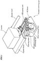
- the ink jet printer of the present invention is provided with a carrier 1 on which a printing head 11 is mounted, a guide shaft 2 to guide the carrier 1, a guide frame 3, a nozzle restoring unit 4 and a driving shaft 5.
- the nozzle restoring unit 4 consists of a frame 41, a capping unit 42 supported by the frame, a negative pressure generating unit 43 and an air releasing unit 44.
- the carrier 1 has a hole through which the guide shaft 2 comes and a sliding member (not shown) and is supported by the guide frame 3 through the guide shaft 2 and the sliding member.
- the carrier 1 is so configured that it can move along the guide shaft 2 in the direction of an axial line by a belt conveying means (not shown) driven by an external driving motor (not shown).
- the printing head 11 is disposed below the carrier 1.
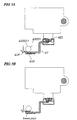
- Figure 2A is a bottom view approximately showing a nozzle forming face 12 of the printing head 11.
- a frame 120 shown by the dotted lines illustrates a contact portion between the top end of the capping unit 42 of the nozzle restoring unit 4 and the nozzle forming face 12.
- a black ink nozzle 121 On the nozzle forming face 12 of the printing head 11 are formed a black ink nozzle 121, a cyan ink nozzle 122, a light cyan ink nozzle 123, a Magenta ink nozzle 124, a light Magenta ink nozzle 125 and a yellow ink nozzle 126 and, as shown in an enlarged view of Fig. 2B, two or more nozzle rows are arranged at equal intervals vertically in the drawing.
- An ink drop as a shape of a piezo device (not shown) disposed at the back of the nozzle changes, is pushed and discharged out of the nozzle.
- the ink jet printer of the present invention is also so configured that printing information to be printed on printing media such as paper is performed by discharging ink out of the nozzle formed on the nozzle forming face 12 of the printing head 11.
- the nozzle restoring unit 4 is placed at a nozzle restoring section disposed at the outside of a printing section where printing is performed by moving the carrier 1 in the direction of an axial line of the guide shaft, and when the printer is not in use, the carrier 1 is returned back to the nozzle restoring section so as to stand ready for subsequent printing.
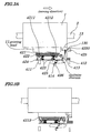
- the capping unit 42 is provided with a cap 421 to seal the nozzle forming face and a pressing means to press the cap 421 to the nozzle forming face.
- the pressing means consists of a cap holder 422, a compressed spring 423, a bracket 424, a cap lever 425 and a tension spring 426.
- the cap 421 is so configured that it is surrounded by an enclosure with a uniform height to make its cross-section concave and is opened on its side opposite to the nozzle forming face 12.
- the cap 421 is made of an elastic material such as rubber and, when the top end of the enclosure is contacted, by pressure, with the nozzle forming face 12, a sealed cap air chamber 4213 (see Fig. 3B) is formed.
- a sucking port 4211 and an air communicating port 4212 respectively.
- the cap holder 422 is disposed below the cap 421. Communicating paths to communicate the sucking port 4211 of the cap 421 with a first tube 46 and communicate the air communicating port 4212 with a second tube 47 respectively are provided.
- the cap 421 is pressed against the nozzle forming face 12 by a protrusion formed at the lower portion of the carrier 1.
- the capping unit 42 is composed of the cap lever 425 which swings with respect to a rotary axis 413 to lift the bracket 424 by being contacted by the protrusion 13 of the carrier 1, the cap holder 422 used to hold the cap 421, by pressure, to the contacting section 120 (see Fig. 2) surrounding the nozzle forming face 12 and to press up the compressed spring 423 so that its loads are imposed uniformly on the contacting section 120, and the bracket 424 to hold the cap holder 422 through the compressed spring 423.
- the bracket 424 is pulled, by the tension spring 426, toward the hook 414 of the tensile spring mounted on the frame 41 and held by holding sections 411 and 412 of the capping unit formed on the frame 41.
- the negative pressure generating unit 43 contains a diaphragm pump communicating with the cap 421 by the first tube 46 and a pump driving unit to transfer external driving power to the diaphragm pump.
- the diaphragm pump is provided with a cover 4311, a diaphragm 4312, a pump frame 4313, a shaft cover 4314, a shaft 4315 and a loading ring 4316.
- the cover 4311 has a cap communicating port 43110 into which the tube 46 is inserted to be connected thereto.
- the diaphragm 4312 co-operates with the cover 4311 to form a pump chamber 4310 having variable volume.
- the pump frame 4313 is used to seal and hold the cover 4311 and the diaphragm 4312 against the cover lock section 415 formed by the frame 41.
- the shaft cover 4314 is used to supply a force that acts on a bottom surface 43120 of the diaphragm 4312 and push the same in the direction to reduce the volume of the pump chamber 4310.
- the shaft 4315 has a disc-shaped valve section 43150 within the pump chamber 4310 and have the pump chamber cut off from air by bringing the disc-shaped valve section 43150 into intimate contact with the bottom surface of the diaphragm 4312.
- the loading ring 4316 is located between a pump frame holding section 416 formed by the frame 41 and the pump frame 4313.
- the loading ring 4316 is used to impose loads on the shaft cover 4314 when the shaft cover accomplishes up-and-down movements.
- the pump driving unit has a swinging pump lever 4320, a first gear 4321 and a second gear 4324 engaged with the first gear 4321.
- the second gear 4324 is constructed so as to be integral with a cam shaft 4322 and the former drives the latter to be rotated.
- the cam shaft 4322 has a first cam 43220 and a second cam 43221.
- the swinging pump lever 4320 of the pump driving unit is coupled to the shaft 4315 of the pump with a pin 4323.
- the pump lever 4320 is supported so as to be swung by a shaft 43200 connected to the bearing 417 at its hinged support.
- the first gear 4321 is coupled, by the application of pressure, to the driving shaft 5 in the direction of the axis line and is made rotatable integrally with the driving shaft 5.
- the second gear 4324 is adapted to engage with the first gear 4321.
- the second gear 4324 is constructed so as to be integral with the cam shaft 4322 equipped with the first cam 43220 and the second cam 43221.
- the first cam 43220 of the cam shaft 4322 is placed at a position where it can engage with a cam curving surface 43201 of the pump lever 4320.
- the first cam 43220 is adapted to transfer movements, by sliding the cam curving surface 43201 of the pump lever 4320, to the shaft 4315 coupled to the pump lever 4329 with the pin 4323.
- the force given by the second cam 43221 acts on the air releasing unit 44. Since the first cam 43220 and the second cam 43221 are adapted to rotate around the same rotary axis, they rotate in synchronization with each other.
- phases of the first cam 43220 and the second cam 43221 are set so that, before a nose 32200 of the first cam 43220 points to the lowest point representing the termination of a negative pressure generating operation of the pump driving unit, i.e., when it points to a position where an angle of ⁇ is formed with respect to the lowest point, the flat face 432210 of the second cam points to the direction of the lowest point.
- the air releasing unit 44 is provided with the tube 47, one end of which is communicated with the cap 421 and the other end of which is used to release air, a crushing member 418 formed on the frame 41 and used to crush the tube 47 using the second cam 43221 to cut off air and a receiving member 419 used to support the tube when crushed.
- the tube 47 is held by the crushing member and the receiving member 419.
- the cap lever 425 rotates around a hinged support 413 in a clockwise direction and a right protrusion 4251 of the cap lever 425 lifts the bracket 424 upward.
- the bracket 424 lifts a cap holder 422 used to hold the cap 421 through the compressed spring 423 and presses the cap 421 against the nozzle forming face 12 as shown in Fig. 3B.
- a cap air chamber (i.e., sealed space) 4213 is formed by the nozzle forming face 12 and the cap 421.
- the negative pressure generating unit 43 is activated. That is, an external driving force (not shown) is transferred, through the driving shaft 5, to the first gear 4321. Then, the cam shaft 4322 is rotated through the second gear 4323.
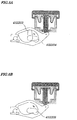
- the first cam 43220 is rotated, for example, from a lowest point 432200 where the first cam 43220 now exists, to the direction of an arrow mark (in a clockwise direction) as shown in Fig. 4A and, at the first rotation position 432201 shown by chain lines, the nose 432200 of the first cam 43220 is contacted with the cam curving surface 43201 of the pump lever 4320 (at first rotation position in Fig. 9).
- the first cam 43220 When the first cam 43220 is further rotated, it drives the pump lever 4320 while contacting with the cam curving surface 43201 of the pump lever 4320. This causes the pump lever 4320 to swing around the rotary axis 43200 in a counterclockwise direction and to begin to lift the shaft 4315 through the pin 4323.
- the first cam 43220 is rotated from the rotation position 432201 to the other position 432202, as shown in Fig. 4B, because the disc-shaped valve section 43150 of the shaft 4315 leaves a bottom face 43120 of the diaphragm 4312, air is allowed to enter or go out of, the pump chamber 4310 through a clearance 43140 between the shaft cover 4314 and the shaft 4315.
- a right upper face 43202 of the pump lever 4320 lifts the shaft cover 4314, and in response to this action, the shaft cover 4314 lifts a bottom face 43120 of the diaphragm 4312.
- the pump moves from the position of the bottom dead center where the volume of the pump chamber 4310 is maximized to the position of the top dead center where the volume of the pump chamber 4310 is minimized (refer to Figs. 5A and 9).
- This causes the pump chamber 4310 to release air within the chamber into the atmosphere through the clearance 43140 and to reduce its volume. Because of this, waste ink collected in the pump chamber 4310 is discharged downward through the clearance 43140 and flows into a waste ink container (not shown).
- the first cam 43220 rotates from the rotation position 432203 to a position 432204 shown by chain lines in Fig. 5 and again contacts the pump lever 4320.
- the pump lever 4320 begins to pull down the shaft 4315 through the pin 4323.
- the disc-shaped valve section 43150 of the shaft 4315 comes into contact with the bottom face 43120 of the diaphragm 4312 to block the clearance 43140 so that the pump chamber 4310 is cut off from the atmosphere and sealed.
- This point is a starting point of sucking stroke of the pump (refer to Fig. 9) .
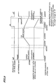
- the printing head 11 is turned ON, ink discharging operation from the nozzle is started and ink drops are discharged into the cap air chamber 4213 (refer to Fig. 9).
- the pump lever 4320 swings to pull the shaft 4315 down further, causing the volume of the pumping chamber 4310 to be increased and the sucking stroke to start. As the volume of the pump chamber 4310 increases, negative pressure is generated within the pump chamber 4310. The negative pressure is transferred to the cap air chamber 4213 through the communicating port 43110 of the cover 4311 and the tube 46.
- This negative pressure acts on each nozzle of the printing head 11 facing the cap air chamber.
- By the action of the negative pressure within the cap air chamber 4213 in cooperation with actions of pressure of ink drops jetted from the nozzle, thickened ink, dust and the like within the nozzle are sucked out and collected in the cap air chamber 4213.
- the pump since the pump moves from its top dead center to its bottom dead center, waste ink within the cap air chamber 4213 is sucked out and collected within the pump chamber 4310.
- the air releasing unit 44 begins to perform air releasing operation to cause the pressure within the cap air chamber to be atmospheric pressure.
- the flat face 432211 of the second cam 43221 points to the direction of the lowest point, the crushing member 418 crushing the tube 47 is released, allowing the atmosphere to come into the cap air chamber 4213 through the communicated tube 47.
- the cap air chamber 4213 sucks air through the air communicating port 4212 and the pump sucks the waste ink and air combined with the waste ink within the cap air chamber 4213.
- the first cam 43220 further rotates to the front of the rotation position 432200.
- the printing head 11 is turned OFF and the discharging of ink from the nozzle is terminated.
- no negative pressure acts on the nozzle.
- the pump When the first cam 43220 further rotates to the rotation position 432200, the pump reaches its bottom dead center and sucks the waste ink and air combined with the waste ink within the cap air chamber 4213, and the air releasing unit 44 crushes the tube 47 to cut off air and the air releasing operation is terminated.
- the air releasing means is activated to release the nozzle to the atmosphere, there is no residue of the negative pressure within the nozzle after sucking process by negative pressure is terminated. Accordingly, the waste ink collected within the cap after being sucked in the sucking process does not flow backward to the nozzle, thus preventing the contamination and/or mixing of color of ink caused by the waste ink
- the present invention because there is no need for using a keeping box, the clogging in the nozzle caused by the thickened ink, dust and the like can be prevented, thus providing restored normal printing capability.
- the negative pressure generating means and the air releasing means are individually driven by two cam members, each having a different phase, mounted on the same cum axis.
- the ink jet printer is so configured that the negative suction and air releasing can be performed by a predetermined timing in a simplest way.
Landscapes
- Ink Jet (AREA)
Priority Applications (3)
| Application Number | Priority Date | Filing Date | Title |
|---|---|---|---|
| JP10188938A JP2000015839A (ja) | 1998-07-03 | 1998-07-03 | インクジェット記録装置 |
| US09/408,978 US6220690B1 (en) | 1998-07-03 | 1999-09-29 | Ink jet printer |
| EP99119131A EP1090765A1 (fr) | 1998-07-03 | 1999-10-05 | Imprimante à jet d'encre |
Applications Claiming Priority (3)
| Application Number | Priority Date | Filing Date | Title |
|---|---|---|---|
| JP10188938A JP2000015839A (ja) | 1998-07-03 | 1998-07-03 | インクジェット記録装置 |
| US09/408,978 US6220690B1 (en) | 1998-07-03 | 1999-09-29 | Ink jet printer |
| EP99119131A EP1090765A1 (fr) | 1998-07-03 | 1999-10-05 | Imprimante à jet d'encre |
Publications (1)
| Publication Number | Publication Date |
|---|---|
| EP1090765A1 true EP1090765A1 (fr) | 2001-04-11 |
Family
ID=27240025
Family Applications (1)
| Application Number | Title | Priority Date | Filing Date |
|---|---|---|---|
| EP99119131A Withdrawn EP1090765A1 (fr) | 1998-07-03 | 1999-10-05 | Imprimante à jet d'encre |
Country Status (3)
| Country | Link |
|---|---|
| US (1) | US6220690B1 (fr) |
| EP (1) | EP1090765A1 (fr) |
| JP (1) | JP2000015839A (fr) |
Families Citing this family (5)
| Publication number | Priority date | Publication date | Assignee | Title |
|---|---|---|---|---|
| HK1055580A1 (en) * | 2000-07-07 | 2004-01-16 | Seiko Epson Corporation | Ink feed unit for ink jet recorder and diaphragm valve |
| JP4860810B2 (ja) * | 2000-10-19 | 2012-01-25 | キヤノン株式会社 | インクジェット記録装置及び吐出回復方法 |
| JP4944296B2 (ja) * | 2000-11-01 | 2012-05-30 | キヤノン株式会社 | インクジェット記録装置及び吐出回復方法 |
| JP5533457B2 (ja) | 2010-09-02 | 2014-06-25 | 株式会社リコー | 画像形成装置 |
| JP2013256102A (ja) * | 2012-05-14 | 2013-12-26 | Seiko Epson Corp | インクジェット記録装置 |
Citations (7)
| Publication number | Priority date | Publication date | Assignee | Title |
|---|---|---|---|---|
| US4745414A (en) * | 1986-04-09 | 1988-05-17 | Canon Kabushiki Kaisha | Recovery device for an ink jet recorder and a recovery method thereof |
| EP0286841A2 (fr) * | 1987-03-13 | 1988-10-19 | Canon Kabushiki Kaisha | Dispositif de désobstruction pour un enregistreur à jet d'encre |
| US4999643A (en) * | 1984-11-19 | 1991-03-12 | Canon Kabushiki Kaisha | Discharge recovery device and apparatus having suction means and vent means communicating with capping means |
| EP0423475A1 (fr) * | 1989-08-31 | 1991-04-24 | Canon Kabushiki Kaisha | Dispositif de remise en état par succion pour un appareil d'enregistrement à jet d'encre |
| EP0482775A1 (fr) * | 1990-10-03 | 1992-04-29 | Canon Kabushiki Kaisha | Appareil d'enregistrement à jet d'encre |
| US5126766A (en) * | 1989-03-17 | 1992-06-30 | Canon Kabushiki Kaisha | Ink jet recording apparatus including means for opening and closing an ink supply path |
| US5898444A (en) * | 1995-06-13 | 1999-04-27 | Seiko Epson Corporation | Ink jet type recording apparatus having a capping device and a CAM follower |
Family Cites Families (5)
| Publication number | Priority date | Publication date | Assignee | Title |
|---|---|---|---|---|
| US4628333A (en) * | 1983-12-29 | 1986-12-09 | Canon Kabushiki Kaisha | Ink jet recording head and ink jet recorder |
| JPH089231B2 (ja) * | 1984-01-31 | 1996-01-31 | キヤノン株式会社 | 吐出回復方法 |
| US4695851A (en) * | 1984-02-24 | 1987-09-22 | Canon Kabushiki Kaisha | Ink jet printer |
| US5701146A (en) * | 1991-10-18 | 1997-12-23 | Canon Kabushiki Kaisha | Ink head recovery method and apparatus |
| JP3253766B2 (ja) * | 1993-07-06 | 2002-02-04 | キヤノン株式会社 | インクジェット記録装置用回復処理装置 |
-
1998
- 1998-07-03 JP JP10188938A patent/JP2000015839A/ja active Pending
-
1999
- 1999-09-29 US US09/408,978 patent/US6220690B1/en not_active Expired - Fee Related
- 1999-10-05 EP EP99119131A patent/EP1090765A1/fr not_active Withdrawn
Patent Citations (7)
| Publication number | Priority date | Publication date | Assignee | Title |
|---|---|---|---|---|
| US4999643A (en) * | 1984-11-19 | 1991-03-12 | Canon Kabushiki Kaisha | Discharge recovery device and apparatus having suction means and vent means communicating with capping means |
| US4745414A (en) * | 1986-04-09 | 1988-05-17 | Canon Kabushiki Kaisha | Recovery device for an ink jet recorder and a recovery method thereof |
| EP0286841A2 (fr) * | 1987-03-13 | 1988-10-19 | Canon Kabushiki Kaisha | Dispositif de désobstruction pour un enregistreur à jet d'encre |
| US5126766A (en) * | 1989-03-17 | 1992-06-30 | Canon Kabushiki Kaisha | Ink jet recording apparatus including means for opening and closing an ink supply path |
| EP0423475A1 (fr) * | 1989-08-31 | 1991-04-24 | Canon Kabushiki Kaisha | Dispositif de remise en état par succion pour un appareil d'enregistrement à jet d'encre |
| EP0482775A1 (fr) * | 1990-10-03 | 1992-04-29 | Canon Kabushiki Kaisha | Appareil d'enregistrement à jet d'encre |
| US5898444A (en) * | 1995-06-13 | 1999-04-27 | Seiko Epson Corporation | Ink jet type recording apparatus having a capping device and a CAM follower |
Also Published As
| Publication number | Publication date |
|---|---|
| JP2000015839A (ja) | 2000-01-18 |
| US6220690B1 (en) | 2001-04-24 |
Similar Documents
| Publication | Publication Date | Title |
|---|---|---|
| US6578949B2 (en) | Ink jet recording device and method of driving and controlling the same | |
| JP3161155B2 (ja) | カラーインクジェット記録装置の吐出性能維持装置 | |
| US5170186A (en) | Ink jet recording apparatus with dry absorption control of recording head cap | |
| US6164767A (en) | Ink jet recording apparatus having a driving wheel mechanism for pressurizing tubes of a tube pump | |
| JP2025120450A (ja) | 液体吐出装置 | |
| US6612683B2 (en) | Ink supply recovery system, ink-jet printing apparatus and image pick-up device having recording mechanism | |
| JP4802467B2 (ja) | インクジェットプリンタ | |
| US6637857B2 (en) | Ink jet recording apparatus and cleaning control method for wiping device in the apparatus | |
| US6220690B1 (en) | Ink jet printer | |
| JP2003237092A (ja) | インクジェット記録装置 | |
| JP3543314B2 (ja) | インクジェット式記録装置 | |
| JP4141603B2 (ja) | インクジェット式記録装置 | |
| JPH1024607A (ja) | インクジェットプリンタ | |
| JP2008012684A (ja) | インクジェット記録装置 | |
| JP2723538B2 (ja) | カラーインクジェット記録装置 | |
| JPH08267787A (ja) | インクジェットプリンタ | |
| KR100671806B1 (ko) | 잉크 흡인 장치, 잉크젯 기록 헤드 회복 장치, 잉크젯기록 장치 및 잉크 흡인 방법 | |
| JP4006914B2 (ja) | インクジェット式記録装置 | |
| KR100198224B1 (ko) | 잉크제트 프린터의 인쇄헤드 캡핑 장치 | |
| JP2000062208A (ja) | チューブポンプおよびこれを用いたインクジェット式記録装置 | |
| US6502932B1 (en) | Print head device and ink jet printer including the print head device | |
| JP3112618B2 (ja) | インクジェットプリント装置 | |
| GB2315816A (en) | Tube pump for ink jet recording apparatus | |
| JP2001158110A (ja) | 排インク収容装置、排インク容器及びインクジェット記録装置 | |
| JP3253763B2 (ja) | インクジェット記録装置 |
Legal Events
| Date | Code | Title | Description |
|---|---|---|---|
| PUAI | Public reference made under article 153(3) epc to a published international application that has entered the european phase |
Free format text: ORIGINAL CODE: 0009012 |
|
| 17P | Request for examination filed |
Effective date: 20000329 |
|
| AK | Designated contracting states |
Kind code of ref document: A1 Designated state(s): DE FR GB |
|
| AX | Request for extension of the european patent |
Free format text: AL;LT;LV;MK;RO;SI |
|
| GRAG | Despatch of communication of intention to grant |
Free format text: ORIGINAL CODE: EPIDOS AGRA |
|
| GRAG | Despatch of communication of intention to grant |
Free format text: ORIGINAL CODE: EPIDOS AGRA |
|
| GRAG | Despatch of communication of intention to grant |
Free format text: ORIGINAL CODE: EPIDOS AGRA |
|
| GRAH | Despatch of communication of intention to grant a patent |
Free format text: ORIGINAL CODE: EPIDOS IGRA |
|
| AKX | Designation fees paid |
Free format text: DE FR GB |
|
| STAA | Information on the status of an ep patent application or granted ep patent |
Free format text: STATUS: THE APPLICATION IS DEEMED TO BE WITHDRAWN |
|
| 18D | Application deemed to be withdrawn |
Effective date: 20020307 |