EP1090768B1 - Imprimante à jet d'encre avec bloc de connection éliminant automatiquement les bulles emprisonnées dans un filtre - Google Patents
Imprimante à jet d'encre avec bloc de connection éliminant automatiquement les bulles emprisonnées dans un filtre Download PDFInfo
- Publication number
- EP1090768B1 EP1090768B1 EP00121780A EP00121780A EP1090768B1 EP 1090768 B1 EP1090768 B1 EP 1090768B1 EP 00121780 A EP00121780 A EP 00121780A EP 00121780 A EP00121780 A EP 00121780A EP 1090768 B1 EP1090768 B1 EP 1090768B1
- Authority
- EP
- European Patent Office
- Prior art keywords
- ink
- path
- filter
- supply
- bubble
- Prior art date
- Legal status (The legal status is an assumption and is not a legal conclusion. Google has not performed a legal analysis and makes no representation as to the accuracy of the status listed.)
- Expired - Lifetime
Links
- 230000000630 rising effect Effects 0.000 claims description 4
- 238000011144 upstream manufacturing Methods 0.000 claims description 3
- 239000000463 material Substances 0.000 abstract description 8
- 230000007547 defect Effects 0.000 abstract description 5
- 230000007246 mechanism Effects 0.000 description 16
- 238000010586 diagram Methods 0.000 description 7
- 230000008901 benefit Effects 0.000 description 5
- 238000012986 modification Methods 0.000 description 2
- 230000004048 modification Effects 0.000 description 2
- 238000011084 recovery Methods 0.000 description 2
- 230000008859 change Effects 0.000 description 1
- 230000007423 decrease Effects 0.000 description 1
- 230000005484 gravity Effects 0.000 description 1
- 238000004519 manufacturing process Methods 0.000 description 1
- 238000012856 packing Methods 0.000 description 1
- 230000000149 penetrating effect Effects 0.000 description 1
- 238000005086 pumping Methods 0.000 description 1
- 239000002699 waste material Substances 0.000 description 1
Images




Classifications
-
- B—PERFORMING OPERATIONS; TRANSPORTING
- B41—PRINTING; LINING MACHINES; TYPEWRITERS; STAMPS
- B41J—TYPEWRITERS; SELECTIVE PRINTING MECHANISMS, i.e. MECHANISMS PRINTING OTHERWISE THAN FROM A FORME; CORRECTION OF TYPOGRAPHICAL ERRORS
- B41J2/00—Typewriters or selective printing mechanisms characterised by the printing or marking process for which they are designed
- B41J2/005—Typewriters or selective printing mechanisms characterised by the printing or marking process for which they are designed characterised by bringing liquid or particles selectively into contact with a printing material
- B41J2/01—Ink jet
- B41J2/17—Ink jet characterised by ink handling
- B41J2/175—Ink supply systems ; Circuit parts therefor
- B41J2/17503—Ink cartridges
- B41J2/1752—Mounting within the printer
- B41J2/17523—Ink connection
-
- B—PERFORMING OPERATIONS; TRANSPORTING
- B41—PRINTING; LINING MACHINES; TYPEWRITERS; STAMPS
- B41J—TYPEWRITERS; SELECTIVE PRINTING MECHANISMS, i.e. MECHANISMS PRINTING OTHERWISE THAN FROM A FORME; CORRECTION OF TYPOGRAPHICAL ERRORS
- B41J2/00—Typewriters or selective printing mechanisms characterised by the printing or marking process for which they are designed
- B41J2/005—Typewriters or selective printing mechanisms characterised by the printing or marking process for which they are designed characterised by bringing liquid or particles selectively into contact with a printing material
- B41J2/01—Ink jet
- B41J2/17—Ink jet characterised by ink handling
- B41J2/175—Ink supply systems ; Circuit parts therefor
- B41J2/17563—Ink filters
-
- B—PERFORMING OPERATIONS; TRANSPORTING
- B41—PRINTING; LINING MACHINES; TYPEWRITERS; STAMPS
- B41J—TYPEWRITERS; SELECTIVE PRINTING MECHANISMS, i.e. MECHANISMS PRINTING OTHERWISE THAN FROM A FORME; CORRECTION OF TYPOGRAPHICAL ERRORS
- B41J2/00—Typewriters or selective printing mechanisms characterised by the printing or marking process for which they are designed
- B41J2/005—Typewriters or selective printing mechanisms characterised by the printing or marking process for which they are designed characterised by bringing liquid or particles selectively into contact with a printing material
- B41J2/01—Ink jet
- B41J2/17—Ink jet characterised by ink handling
- B41J2/19—Ink jet characterised by ink handling for removing air bubbles
Definitions
- the present invention relates to an inkjet printer having a filter for removing foreign materials from ink, wherein the filter is disposed in an ink path for supplying ink to the inkjet head. More particularly, the present invention relates to an inkjet printer capable of avoiding print defects and other problems resulting from air bubbles trapped at the ink filter.
- the ink nozzles of the inkjet head can become clogged, leading to ink discharge problems and printing defects.
- a filter for removing such foreign materials is, therefore, commonly disposed in the ink supply path near the inkjet head to prevent the foreign materials from penetrating the inkjet head together with the ink.
- Removable ink cartridges are now often used as the ink tank. Removing an empty ink cartridge to replace it exposes the ink supply path to the air, which can then enter the ink supply path and become trapped therein, forming a bubble. After the ink cartridge is replaced, and the ink charging operation is performed to supply ink from the ink cartridge to the inkjet head, the air bubble inside the ink supply path is also pushed toward the inkjet head.
- the trapped air bubble makes ink supply unstable. As a result, when the required volume of ink is not supplied to the ink nozzle, ink drop discharge defects occur. Furthermore, when the trapped bubble grows to a sufficient size, it can completely block ink drop discharge.
- the present invention has been developed in light of the above noted problems. It is, therefore, an object of the present invention to provide an inkjet printer that can automatically eliminate bubbles trapped in the filter.
- an inkjet printer includes: an inkjet head; an ink-intake opening formed in the inkjet head; a filter for removing foreign materials contained in ink supplied to the ink-intake opening, the filter being disposed in an ink path on an upstream side of the ink-intake opening; and a connection block disposed above the filter and having an ink path to the filter.
- the connection block has an ink-supply-line part wherein an ink-path portion is formed with a substantially constant shape in cross section, and an ink-path-connection part forms another ink-path portion extending from the bottom of the ink-supply-line part to the filter.
- the internal volume of the ink-path-connection part is equal to or less than the volume of a sphere internally tangent to the ink-supply-line part.
- the ink-path-connection part of the connection block has a substantially conical shape.
- the resulting tapered shape thus permits the bubbles on the filter top to rise reliably along the tapered surface and pass out from the ink path.
- the inside wall surface forming the ink-path-connection part is an inwardly bulging curved surface.
- the ink-supply-line part and ink-path-connection part of the connection block are disposed substantially vertically. This arrangement assures that there is nothing on the inside surface of the ink-supply-line part and ink-path-connection part obstructing the rise of the bubble. Thus, bubbles are reliably expelled.
- the sectional shape of the ink-path-connection part is substantially cylindrical.
- the filter is disposed at the ink-intake opening, near the inkjet head. Disposing the filter near the inkjet head assures that bubbles reliably can be prevented from entering the inkjet head.
- a bubble trap ⁇ for holding a bubble rising through the ink-supply-line part ⁇ is disposed above the connection block on an upstream side of the ink path. Bubbles, trapped at the filter, which then rise by buoyancy up through the connection block, can be captured and held in the bubble trap. As a result, once bubbles are removed from the filter surface, they can be prevented from flowing back through the ink-supply-line part to the filter wherein they would again become trapped at the filter surface.
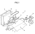
- Fig. 1 is a schematic diagram of an inkjet printer according to the present invention. As shown in Fig. 1, this inkjet printer 1 has an inkjet head 2, a carriage 3 supporting the inkjet head 2, a belt drive mechanism 4 for moving the carriage 3 bi-directionally in the main scanning direction as indicated by arrow A, and a guide shaft 5 for guiding the movement of the carriage 3.
- the ink-nozzle surface of the inkjet head 2 faces downward in this exemplary embodiment.
- a platen roller 6 is disposed opposite and below the ink-nozzle surface.
- Printing paper 7 is advanced by platen roller 6 in the subscanning direction (indicated by arrow B) so that the desired text or graphic information can be printed on the surface of the printing paper 7.
- ink pressure attenuating mechanism 8 mounted on the carriage 3 is an ink pressure attenuating mechanism 8. Ink is supplied from an ink cartridge 10, which is held removably on ink cartridge holder 9, through ink tube 11 and ink pressure attenuating mechanism 8, to the inkjet head 2.
- a waste-ink recovery mechanism 13 is disposed at a position outside the print area in the main scanning direction of the inkjet head 2.
- This waste-ink recovery mechanism 13 has a cap 14 for capping the ink-nozzle surface of the inkjet head 2, and has a suction pump 17. Waste ink deposited into cap 14 is transferred by suction pump 17 into a waste-ink tank 16 through waste-ink tube 15.
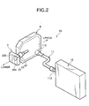
- Fig. 2 shows the ink supply mechanism of Fig. 1
- Fig. 3 is a cross section view of the ink supply mechanism shown in Fig. 2.
- ink supply mechanism 20 generally includes ink cartridge 10, ink tube 11, and ink pressure attenuating mechanism 8.
- the ink cartridge 10 has a flat, rectangularly shaped hard case 101, and a flexible ink sack 102 housed inside the hard case 101. Ink is sealed inside the ink sack 102.
- the ink sack 102 further has an ink outlet 103, which protrudes outside of hard case 101.
- ink supply needle 112 affixed to one end of ink tube 11, is inserted into ink outlet 103 of ink cartridge 10.
- the ink supply needle 112 is fixed to inkjet printer 1 such that installing and removing ink cartridge 10 causes the ink supply needle 112 to be inserted to and removed from ink outlet 103.
- the other end of ink tube 11 is connected to ink-pressure attenuating mechanism 8.
- the ink-pressure attenuating mechanism 8 has a flat, rectangularly shaped, hard case 81, a soft film 82 disposed on the hard case 81 so as to cover an opening in the hard case 81, and a leaf spring 83 affixed to the inside of the soft film 82.
- a pressure attenuation chamber 80 is formed between the hard case 81 and the soft film 82.
- the hard case 81 also has an ink inlet 84 and an ink outlet 85 formed therein.
- the ink tube 11 is connected to the ink inlet 84, whereas the ink outlet 85 communicates with the top end of an ink-outflow path 86 formed in the hard case 81.
- the bottom end of this ink-outflow path 86 forms a large diameter head connector 87.
- a specific volume of ink 40 is held in the pressure attenuation chamber 80 of the thusly formed ink pressure attenuating mechanism 8.
- the pressure change causes the soft film 82 and the leaf spring 83 to deform flexibly to the outside or inside, thereby adjusting the internal volume of the pressure attenuation chamber 80.
- Deformation of the soft film 82 thus functions to keep the internal pressure of the pressure attenuation chamber 80 constant. This means that even if the ink pressure at the ink inlet 84 varies, the ink supply pressure from ink outlet 85 to inkjet head 2 is kept constant.
- inkjet head 2 has an ink chamber 201 for holding ink, and an ink-intake opening 202 for taking ink into the ink chamber 201. Ink is thus supplied from ink chamber 201 to the ink nozzles 203. As noted above, inkjet head 2 is held in carriage 3 so that the ink-nozzle surface 204 faces down. The ink-intake opening 202 is open to the unit case top 210 of inkjet head 2.
- connection block 21 is attached to the unit case top 210 at a position matching ink-intake opening 202.
- the connection block 21 has an ink-supply-line part 23 for connecting with ink pressure attenuating mechanism 8, and a generally conically shaped connector 22 having an ink-path-connection part 222.
- An ink path extends through the connection block 21.
- the ink-supply-line part 23 is formed so that the internal diameter d is substantially constant and forms a first ink-path portion through the connection block 21.
- the top end part of the ink-supply-line part 23 is inserted from below into the head connector 87 so that packing 88 is deformed to prevent ink leakage.
- a filter 24, for removing foreign materials from ink supplied from the connection block 21 to the inkjet head 2, is disposed directly above ink-intake opening 202, and is sandwiched between the connection block 21 and the unit case top 210.
- the ink-path-connection part 222 includes the ink path formed on the inside of connector 22 ⁇ the inside of which is conically shaped ⁇ a large diameter bottom end 221 communicating with ink-intake opening 202, a small diameter top end 223 communicating with ink-supply-line part 23, and a filter holder 224 formed in the bottom end 221.
- the ink-path-connection part 222 is a conically shaped part extending from filter holder 224 to top end 223.
- the internal volume of ink-path-connection part 222, between filter top 24a and top end 223, is the same as or less than 1.1 times the volume of a sphere internally tangent to ink-supply-line part 23, i.e., a sphere having a diameter d.
- the internal volume of the ink-path-connection part 222 is set equal to the volume of a sphere internally tangent to ink-supply-line part 23.
- an air bubble can enter the ink supply path when the ink cartridge 10 of a inkjet printer 1 is replaced. Furthermore, when ink-nozzle surface 204 of inkjet head 2 is capped with cap 14, and ink is transferred by way of the ink suction operation of suction pump 17, a bubble 30 in the ink supply path can advance to filter 24. Once it has reached the filter 24, the bubble 30 becomes trapped by filter top 24a, forming a flattened hemisphere that can substantially cover the filter top 24a.
- ink-path-connection part 222 is conically shaped, a bubble 30 trapped at filter top 24a can float quickly upward from filter top 24a, and can float along the tapered inside surface of ink-path-connection part 222. It is thus also possible to avoid problems caused by bubbles being trapped in a corner area ⁇ i.e., where there is a horizontal downward facing surface formed inside the ink-path-connection part ⁇ when the bubble rises.
- a bubble trap 89 for holding any bubble 30A which rises through the top of the vertically disposed ink-supply-line part 23.
- Such bubble trap 89 prevents bubbles from passing back to the filter 24.
- the bubble trap 89 is formed in the top part of the attenuation chamber 80, above the ink inlet 84.
- connection block 21a according to a second embodiment of the present invention is described.
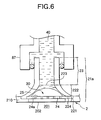
- Fig. 6 is similar to Fig. 4 which shows the connection block 21 of the first embodiment. Further, the configuration and function of parts other than the connection block 21a are as noted in the above-described first embodiment. That is, like parts in this and the first embodiment are indicated by like reference numbers and, therefore, further description thereof is omitted.
- connection block 21a of this embodiment differs from the connection block 21 of the first embodiment in that it includes a connector 25, the inside wall of which connector 25 is curved.
- the ink-path-connection part 222 includes the ink path formed on the inside of connector 25 ⁇ the inside wall of which is curved ⁇ a large diameter bottom end 221 communicating with the ink-intake opening 202, a small diameter top end 223 communicating with the ink-supply-line part 23, and a filter holder 224 formed in the bottom end 221.
- the inside wall of the ink-path-connection part 222 is curved such that it bulges inwardly and narrows in diameter from filter holder 224 to top end 223.
- the internal volume of the ink-path-connection part 222, between filter top 24a and top end 223, is the same as or less than 1.1 times the volume of a sphere internally tangent to ink-supply-line part 23.
- the internal volume of ink-path-connection part 222 is set equal to the volume of a sphere internally tangent to ink-supply-line part 23, i.e., a sphere having a diameter that is the same as the inside diameter of the ink-supply-line part 23.
- the structure of the second embodiment additionally makes it easier for bubbles to separate from the top surface of the filter.
- connection 21b block according to a third embodiment of the present invention is described.
- Fig. 7 is similar to Fig. 4 which shows the connection block 21 of the first embodiment. Further, the configuration and function of parts other than the connection block 21b are as noted in the above-described first embodiment. That is, like parts in this and the first embodiment are indicated by like reference numbers and, therefore, further description thereof is omitted.
- connection block 21b of this embodiment differs from the connection block 21 of the first embodiment in that it includes a connector 26.
- the inside wall of the connector 26 is cylindrical and is stepped relative to ink-supply-line part 23. This stepped configuration makes the connection block 21b easier to manufacture than the connection block 21 of the first embodiment.
- the ink-path-connection part 222 includes the ink path formed on the inside of the cylindrically shaped connector 26, a large diameter bottom end 221 communicating with ink-intake opening 202, a small diameter top end 223 communicating with the ink-supply-line part 23, and a filter holder 224 formed in the bottom end 221.
- the ink-path-connection part 222 is thus cylindrically shaped, and extends from the filter holder 224 to the top end 223.
- the internal volume of the ink-path-connection part 222, between filter top 24a and top end 223, is the same as or less than 1.1 times the volume of a sphere internally tangent to ink-supply-line part 23, i.e., a sphere having a diameter which is the same as the inside diameter of the ink-supply-line part 23.
- the internal volume of ink-path-connection part 222 is set equal to the volume of a sphere internally tangent to ink-supply-line part 23.
- This embodiment of the present invention achieves substantially the same benefits as the first embodiment described above.
- connection block 21c according to a fourth embodiment of the present invention is described below with reference to Fig. 8.
- Fig. 8 is similar to Fig. 4 which shows the connection block 21 of the first embodiment. Further, the configuration and function of parts other than the connection block 21c are as noted in the above-described first embodiment. That is, like parts in this and the first embodiment are indicated by like reference numbers and, therefore, further description thereof is omitted.
- connection block 21c of this embodiment includes a connector 27, wherein the inside wall of the connector 27 is a combination of inside walls which are comparable to the inside wall configurations in the above-described first and third embodiments.
- the ink-path-connection part 222 includes the ink path formed on the inside of connector 27 ⁇ the inside wall of which is both cylindrically shaped and conically shaped ⁇ a large diameter bottom end 221 communicating with the ink-intake opening 202, a small diameter top end 223 communicating with ink-supply-line part 23, and a filter holder 224 formed in the bottom end 221.
- the ink-path-connection part 222 is cylindrically and conically shaped, and extends from filter holder 224 to top end 223.
- the internal volume of the ink-path-connection part 222, between filter top 24a and top end 223, is the same as or less than 1.1 times the volume of a sphere internally tangent to ink-supply-line part 23, i.e., a sphere have a diameter which is the same as the inner diameter of the ink-supply-line part 23.
- the internal volume of ink-path-connection part 222 is set equal to the volume of a sphere internally tangent to ink-supply-line part 23.
- This embodiment of the present invention achieves substantially the same benefits as the first embodiment described above.
- ink-nozzle surface 204 of inkjet head 2 is described as facing down in the preceding embodiments, the ink-nozzle surface can be oriented in other directions, including a direction wherein ink is discharged to the side.
- connection block 21, 21a, 21b, 21c is described as being disposed so that the ink-supply-line part 23 is substantially vertical.
- the orientation of the connection block can, however, be changed so that the ink-supply-line part 23 is at an angle of up to approximately 45 degrees to the horizontal.
- the ink-supply-line part 23 is, however, preferably vertical or nearly vertical because this angle makes it easiest for bubbles to separate from the filter surface and, therefore, is most effective.
- the filter 24 is described as being disposed at the ink-intake opening 202 to the ink chamber 201, but the invention is not so limited.
- the filter 24 can be placed elsewhere in the ink path, separate from the inkjet head. But disposition of the filter 24 near the inkjet head 2 makes it easier to prevent bubbles from entering the inkjet head.
- connection block 21, 21a, 21b, 21c are described as being circular in cross section, but they can also have other cross-sectional shapes such as, for example, square.
- the internal volume of the ink-path-connection part 222 is equal to or less than 1.1 times the volume of a sphere internally tangent to the ink-supply-line part 23. With such an ink-path-connection-part volume, the benefits of the present invention, as described above, can be achieved.
Landscapes
- Ink Jet (AREA)
Claims (7)
- Imprimante à jet d'encre comprenant :une tête à jet d'encre ;une ouverture d'aspiration d'encre formée dans la tête à jet d'encre ;un filtre disposé au niveau d'un côté en amont de l'ouverture d'aspiration d'encre ;un bloc de connexion disposé au-dessus du filtre et formant un parcours d'encre dans celui-ci, le parcours d'encre ayant :caractérisée en ce qu'un volume interne de la partie de connexion de parcours d'encre est égal ou inférieur à un volume interne d'une sphère intérieurement tangente à la partie de ligne d'alimentation d'encre.une partie de ligne d'alimentation d'encre formée avec un profile sensiblement constant en coupe transversale suivant une direction d'écoulement de l'encre ; etune partie de connexion de parcours d'encre connectant la partie de ligne d'alimentation d'encre avec le filtre et se dilatant en coupe transversale dans la direction d'écoulement de l'encre
- Imprimante à jet d'encre selon la revendication 1, dans laquelle la partie de connexion de parcours d'encre du bloc de connexion est un profil sensiblement conique.
- Imprimante à jet d'encre selon la revendication 1, dans laquelle la surface intérieure formant la partie de connexion de parcours d'encre est une surface courbe bombée vers l'intérieur.
- Imprimante à jet d'encre selon l'une quelconque des revendications 1 à 3, dans laquelle la partie de ligne d'alimentation d'encre et la partie de connexion de parcours d'encre du bloc de connexion sont disposées sensiblement verticalement.
- Imprimante à jet d'encre selon l'une quelconque des revendications 1 à 4, dans laquelle le parcours d'encre de la partie de ligne d'alimentation d'encre est sensiblement cylindrique.
- Imprimante à jet d'encre selon l'une quelconque des revendications 1 à 5, dans laquelle le filtre est disposé au niveau de l'ouverture d'aspiration d'encre.
- Imprimante à jet d'encre selon l'une quelconque des revendications 1 à 6, comprenant en outre :un piège à bulles pour retenir une bulle montant dans la partie de ligne d'alimentation d'encre, ledit piège à bulles étant disposé au-dessus du bloc de connexion.
Applications Claiming Priority (2)
| Application Number | Priority Date | Filing Date | Title |
|---|---|---|---|
| JP28606699 | 1999-10-06 | ||
| JP28606699 | 1999-10-06 |
Publications (3)
| Publication Number | Publication Date |
|---|---|
| EP1090768A2 EP1090768A2 (fr) | 2001-04-11 |
| EP1090768A3 EP1090768A3 (fr) | 2001-09-26 |
| EP1090768B1 true EP1090768B1 (fr) | 2005-09-21 |
Family
ID=17699521
Family Applications (1)
| Application Number | Title | Priority Date | Filing Date |
|---|---|---|---|
| EP00121780A Expired - Lifetime EP1090768B1 (fr) | 1999-10-06 | 2000-10-05 | Imprimante à jet d'encre avec bloc de connection éliminant automatiquement les bulles emprisonnées dans un filtre |
Country Status (7)
| Country | Link |
|---|---|
| US (1) | US6520632B1 (fr) |
| EP (1) | EP1090768B1 (fr) |
| KR (1) | KR100522212B1 (fr) |
| CN (1) | CN1162276C (fr) |
| AT (1) | ATE304945T1 (fr) |
| DE (1) | DE60022716T2 (fr) |
| ES (1) | ES2250061T3 (fr) |
Families Citing this family (20)
| Publication number | Priority date | Publication date | Assignee | Title |
|---|---|---|---|---|
| GB0121625D0 (en) * | 2001-09-07 | 2001-10-31 | Xaar Technology Ltd | Droplet deposition apparatus |
| US20040257412A1 (en) * | 2003-06-18 | 2004-12-23 | Anderson James D. | Sealed fluidic interfaces for an ink source regulator for an inkjet printer |
| CN1695950B (zh) * | 2004-04-12 | 2010-05-05 | 精工爱普生株式会社 | 液体供给部件和液体喷射装置 |
| JP4526335B2 (ja) * | 2004-09-07 | 2010-08-18 | セイコーエプソン株式会社 | 液滴吐出装置 |
| US7273275B2 (en) * | 2004-11-29 | 2007-09-25 | Lexmark International, Inc. | Air funneling inkjet printhead |
| US7449051B2 (en) * | 2005-07-11 | 2008-11-11 | Hewlett-Packard Development Company, L.P. | Separation of liquid and gas from froth |
| JP4292421B2 (ja) * | 2006-04-27 | 2009-07-08 | セイコーエプソン株式会社 | 液体噴射ヘッド及び液体噴射装置 |
| JP4254808B2 (ja) | 2006-05-24 | 2009-04-15 | セイコーエプソン株式会社 | 液体吐出装置および液体吐出ヘッド |
| JP5146028B2 (ja) * | 2008-03-17 | 2013-02-20 | 株式会社リコー | 画像形成装置 |
| JP5206118B2 (ja) * | 2008-05-27 | 2013-06-12 | セイコーエプソン株式会社 | 液体収容体 |
| JP5056589B2 (ja) * | 2008-05-29 | 2012-10-24 | セイコーエプソン株式会社 | 液体収容体 |
| US8403471B2 (en) * | 2008-09-02 | 2013-03-26 | Seiko Epson Corporation | Defoaming mechanism and liquid ejecting apparatus |
| JP5700975B2 (ja) * | 2010-08-24 | 2015-04-15 | キヤノン株式会社 | インクジェットプリンタ |
| JP5701119B2 (ja) * | 2011-03-23 | 2015-04-15 | キヤノン株式会社 | 液体吐出ヘッドの製造方法 |
| WO2013126045A1 (fr) | 2012-02-21 | 2013-08-29 | Hewlett Packard Development Company, L.P. | Distributeur de fluide |
| US8882254B2 (en) | 2012-05-03 | 2014-11-11 | Fujifilm Corporation | Systems and methods for delivering and recirculating fluids |
| WO2014026149A1 (fr) * | 2012-08-09 | 2014-02-13 | Dp Stud, Inc. D/B/A Deq Systems Corp. | Sabot de distribution de cartes |
| CN106427213A (zh) * | 2016-08-25 | 2017-02-22 | 常州纳捷机电科技有限公司 | 除杂喷墨绘图仪 |
| CN113546449B (zh) * | 2021-06-23 | 2025-04-04 | 浙江广旭数控设备有限公司 | 一种冷却液分离装置 |
| CN114536985A (zh) * | 2022-02-10 | 2022-05-27 | 深圳市华星光电半导体显示技术有限公司 | 墨水容器及喷墨打印装置 |
Family Cites Families (13)
| Publication number | Priority date | Publication date | Assignee | Title |
|---|---|---|---|---|
| JP2992754B2 (ja) | 1986-05-01 | 1999-12-20 | セイコーエプソン株式会社 | インクジエツトプリンター |
| JPH01306257A (ja) | 1988-06-06 | 1989-12-11 | Fujitsu Ltd | インクジェットヘッド |
| JP3108788B2 (ja) * | 1992-03-18 | 2000-11-13 | セイコーエプソン株式会社 | インクジェットヘッドの洗浄方法、及びその装置 |
| DE69418351T2 (de) | 1993-02-02 | 1999-12-30 | Seiko Epson Corp., Tokio/Tokyo | Verfahren zum Befüllen von Tintendurchgängen mit Tinte |
| JP3168122B2 (ja) | 1993-09-03 | 2001-05-21 | キヤノン株式会社 | インクジェットヘッド及び該インクジェットヘッドを備えたインクジェット記録装置 |
| DE19613654B4 (de) * | 1995-04-05 | 2006-04-13 | Seiko Epson Corp. | Tintenstrahlaufzeichnungsvorrichtung |
| JPH0994978A (ja) | 1995-09-29 | 1997-04-08 | Brother Ind Ltd | インク供給源とインクジェットヘッドとの連結装置 |
| JPH09141890A (ja) | 1995-11-24 | 1997-06-03 | Seiko Epson Corp | インクジェット記録装置 |
| WO1999001285A1 (fr) * | 1997-07-02 | 1999-01-14 | Seiko Epson Corporation | Imprimante a jets d'encre |
| JP3493967B2 (ja) | 1997-09-11 | 2004-02-03 | セイコーエプソン株式会社 | インクジェット式記録装置 |
| EP0945272A3 (fr) | 1998-03-27 | 2000-01-26 | Nec Corporation | Tête d'impression pour une imprimante à jet d'encre |
| JP2878271B1 (ja) * | 1998-03-27 | 1999-04-05 | 新潟日本電気株式会社 | インクジェットプリンタ記録ヘッド |
| JP2000071477A (ja) * | 1998-06-17 | 2000-03-07 | Canon Inc | インク供給装置およびインクジェット記録ヘッド |
-
2000
- 2000-10-05 ES ES00121780T patent/ES2250061T3/es not_active Expired - Lifetime
- 2000-10-05 DE DE60022716T patent/DE60022716T2/de not_active Expired - Fee Related
- 2000-10-05 EP EP00121780A patent/EP1090768B1/fr not_active Expired - Lifetime
- 2000-10-05 CN CNB001348949A patent/CN1162276C/zh not_active Expired - Fee Related
- 2000-10-05 US US09/679,613 patent/US6520632B1/en not_active Expired - Fee Related
- 2000-10-05 AT AT00121780T patent/ATE304945T1/de not_active IP Right Cessation
- 2000-10-06 KR KR10-2000-0058918A patent/KR100522212B1/ko not_active Expired - Fee Related
Also Published As
| Publication number | Publication date |
|---|---|
| DE60022716D1 (de) | 2006-02-02 |
| HK1036435A1 (en) | 2002-01-04 |
| EP1090768A2 (fr) | 2001-04-11 |
| EP1090768A3 (fr) | 2001-09-26 |
| ATE304945T1 (de) | 2005-10-15 |
| ES2250061T3 (es) | 2006-04-16 |
| CN1162276C (zh) | 2004-08-18 |
| KR100522212B1 (ko) | 2005-10-14 |
| US6520632B1 (en) | 2003-02-18 |
| KR20010040022A (ko) | 2001-05-15 |
| DE60022716T2 (de) | 2006-04-27 |
| CN1302732A (zh) | 2001-07-11 |
Similar Documents
| Publication | Publication Date | Title |
|---|---|---|
| US6520632B1 (en) | Inkjet printer having a connection block which automatically eliminates bubbles trapped on a filter | |
| JP4770768B2 (ja) | 液滴吐出装置及び液滴吐出装置用のサブタンク | |
| CN100376403C (zh) | 喷墨打印机及其维护方法 | |
| CN100404264C (zh) | 一种墨盒以及具有该墨盒的供墨系统 | |
| JP4047259B2 (ja) | インク供給システム | |
| CN101224672A (zh) | 墨罐和具有这种墨罐的喷墨打印机 | |
| US5828395A (en) | Connecting device between ink supply source and ink jet head | |
| EP3718772B1 (fr) | Appareil d'impression à jet d'encre et réservoir d'encre | |
| JP5428238B2 (ja) | 液体噴射装置 | |
| EP2965912B1 (fr) | Corps renfermant un liquide | |
| JP2017140739A (ja) | フィルターユニット及び液体噴射装置 | |
| JP2019025741A (ja) | 供給液タンクユニットおよびそれを備えたインクジェット記録装置 | |
| JP2009023251A (ja) | インクジェット記録装置 | |
| CN103241002B (zh) | 液体喷射装置、液体收纳体以及液体供给系统 | |
| JP2010105195A (ja) | インクジェット記録装置 | |
| JP4529267B2 (ja) | インクジェットプリンタ | |
| JP2001253093A (ja) | インクジェット式記録装置 | |
| JP2013248894A (ja) | 液体噴射装置 | |
| JP3201053B2 (ja) | インクジェットカートリッジ | |
| JP2012096502A (ja) | 液体噴射装置 | |
| JP7841283B2 (ja) | 液体吐出装置 | |
| CN101157306A (zh) | 墨罐和使用这种墨罐的喷墨打印机 | |
| US20110025788A1 (en) | Fluid Interconnection | |
| JP5315592B2 (ja) | インクジェット記録装置及びその制御方法 | |
| HK1036435B (en) | Ink printer having a connection block which automatically eliminates bubbles trapped in a filter |
Legal Events
| Date | Code | Title | Description |
|---|---|---|---|
| PUAI | Public reference made under article 153(3) epc to a published international application that has entered the european phase |
Free format text: ORIGINAL CODE: 0009012 |
|
| AK | Designated contracting states |
Kind code of ref document: A2 Designated state(s): AT BE CH CY DE DK ES FI FR GB GR IE IT LI LU MC NL PT SE |
|
| AX | Request for extension of the european patent |
Free format text: AL;LT;LV;MK;RO;SI |
|
| PUAL | Search report despatched |
Free format text: ORIGINAL CODE: 0009013 |
|
| AK | Designated contracting states |
Kind code of ref document: A3 Designated state(s): AT BE CH CY DE DK ES FI FR GB GR IE IT LI LU MC NL PT SE |
|
| AX | Request for extension of the european patent |
Free format text: AL;LT;LV;MK;RO;SI |
|
| RIC1 | Information provided on ipc code assigned before grant |
Free format text: 7B 41J 2/175 A, 7B 41J 2/19 B |
|
| 17P | Request for examination filed |
Effective date: 20011210 |
|
| AKX | Designation fees paid |
Free format text: AT BE CH CY DE DK ES FI FR GB GR IE IT LI LU MC NL PT SE |
|
| GRAP | Despatch of communication of intention to grant a patent |
Free format text: ORIGINAL CODE: EPIDOSNIGR1 |
|
| GRAS | Grant fee paid |
Free format text: ORIGINAL CODE: EPIDOSNIGR3 |
|
| GRAA | (expected) grant |
Free format text: ORIGINAL CODE: 0009210 |
|
| AK | Designated contracting states |
Kind code of ref document: B1 Designated state(s): AT BE CH CY DE DK ES FI FR GB GR IE IT LI LU MC NL PT SE |
|
| PG25 | Lapsed in a contracting state [announced via postgrant information from national office to epo] |
Ref country code: AT Free format text: LAPSE BECAUSE OF FAILURE TO SUBMIT A TRANSLATION OF THE DESCRIPTION OR TO PAY THE FEE WITHIN THE PRESCRIBED TIME-LIMIT Effective date: 20050921 Ref country code: FI Free format text: LAPSE BECAUSE OF FAILURE TO SUBMIT A TRANSLATION OF THE DESCRIPTION OR TO PAY THE FEE WITHIN THE PRESCRIBED TIME-LIMIT Effective date: 20050921 |
|
| REG | Reference to a national code |
Ref country code: GB Ref legal event code: FG4D |
|
| REG | Reference to a national code |
Ref country code: CH Ref legal event code: EP Ref country code: CH Ref legal event code: NV Representative=s name: BOVARD AG PATENTANWAELTE |
|
| PG25 | Lapsed in a contracting state [announced via postgrant information from national office to epo] |
Ref country code: CY Free format text: LAPSE BECAUSE OF FAILURE TO SUBMIT A TRANSLATION OF THE DESCRIPTION OR TO PAY THE FEE WITHIN THE PRESCRIBED TIME-LIMIT Effective date: 20051005 Ref country code: IE Free format text: LAPSE BECAUSE OF NON-PAYMENT OF DUE FEES Effective date: 20051005 |
|
| REG | Reference to a national code |
Ref country code: IE Ref legal event code: FG4D |
|
| REF | Corresponds to: |
Ref document number: 60022716 Country of ref document: DE Date of ref document: 20051027 Kind code of ref document: P |
|
| PG25 | Lapsed in a contracting state [announced via postgrant information from national office to epo] |
Ref country code: MC Free format text: LAPSE BECAUSE OF NON-PAYMENT OF DUE FEES Effective date: 20051031 |
|
| PG25 | Lapsed in a contracting state [announced via postgrant information from national office to epo] |
Ref country code: LU Free format text: LAPSE BECAUSE OF NON-PAYMENT OF DUE FEES Effective date: 20051121 |
|
| REG | Reference to a national code |
Ref country code: SE Ref legal event code: TRGR |
|
| PG25 | Lapsed in a contracting state [announced via postgrant information from national office to epo] |
Ref country code: DK Free format text: LAPSE BECAUSE OF FAILURE TO SUBMIT A TRANSLATION OF THE DESCRIPTION OR TO PAY THE FEE WITHIN THE PRESCRIBED TIME-LIMIT Effective date: 20051221 Ref country code: GR Free format text: LAPSE BECAUSE OF FAILURE TO SUBMIT A TRANSLATION OF THE DESCRIPTION OR TO PAY THE FEE WITHIN THE PRESCRIBED TIME-LIMIT Effective date: 20051221 |
|
| REF | Corresponds to: |
Ref document number: 60022716 Country of ref document: DE Date of ref document: 20060202 Kind code of ref document: P |
|
| PG25 | Lapsed in a contracting state [announced via postgrant information from national office to epo] |
Ref country code: PT Free format text: LAPSE BECAUSE OF FAILURE TO SUBMIT A TRANSLATION OF THE DESCRIPTION OR TO PAY THE FEE WITHIN THE PRESCRIBED TIME-LIMIT Effective date: 20060221 |
|
| REG | Reference to a national code |
Ref country code: ES Ref legal event code: FG2A Ref document number: 2250061 Country of ref document: ES Kind code of ref document: T3 |
|
| ET | Fr: translation filed | ||
| PLBE | No opposition filed within time limit |
Free format text: ORIGINAL CODE: 0009261 |
|
| STAA | Information on the status of an ep patent application or granted ep patent |
Free format text: STATUS: NO OPPOSITION FILED WITHIN TIME LIMIT |
|
| REG | Reference to a national code |
Ref country code: IE Ref legal event code: MM4A |
|
| 26N | No opposition filed |
Effective date: 20060622 |
|
| PGFP | Annual fee paid to national office [announced via postgrant information from national office to epo] |
Ref country code: CH Payment date: 20081016 Year of fee payment: 9 Ref country code: DE Payment date: 20081014 Year of fee payment: 9 Ref country code: NL Payment date: 20081015 Year of fee payment: 9 |
|
| PGFP | Annual fee paid to national office [announced via postgrant information from national office to epo] |
Ref country code: ES Payment date: 20081030 Year of fee payment: 9 |
|
| PGFP | Annual fee paid to national office [announced via postgrant information from national office to epo] |
Ref country code: IT Payment date: 20081029 Year of fee payment: 9 Ref country code: BE Payment date: 20081010 Year of fee payment: 9 Ref country code: SE Payment date: 20081022 Year of fee payment: 9 |
|
| PGFP | Annual fee paid to national office [announced via postgrant information from national office to epo] |
Ref country code: FR Payment date: 20081014 Year of fee payment: 9 |
|
| PGFP | Annual fee paid to national office [announced via postgrant information from national office to epo] |
Ref country code: GB Payment date: 20081001 Year of fee payment: 9 |
|
| BERE | Be: lapsed |
Owner name: *SEIKO EPSON CORP. Effective date: 20091031 |
|
| REG | Reference to a national code |
Ref country code: NL Ref legal event code: V1 Effective date: 20100501 |
|
| REG | Reference to a national code |
Ref country code: CH Ref legal event code: PL |
|
| EUG | Se: european patent has lapsed | ||
| REG | Reference to a national code |
Ref country code: FR Ref legal event code: ST Effective date: 20100630 |
|
| PG25 | Lapsed in a contracting state [announced via postgrant information from national office to epo] |
Ref country code: NL Free format text: LAPSE BECAUSE OF NON-PAYMENT OF DUE FEES Effective date: 20100501 Ref country code: FR Free format text: LAPSE BECAUSE OF NON-PAYMENT OF DUE FEES Effective date: 20091102 Ref country code: DE Free format text: LAPSE BECAUSE OF NON-PAYMENT OF DUE FEES Effective date: 20100501 |
|
| PG25 | Lapsed in a contracting state [announced via postgrant information from national office to epo] |
Ref country code: BE Free format text: LAPSE BECAUSE OF NON-PAYMENT OF DUE FEES Effective date: 20091031 Ref country code: LI Free format text: LAPSE BECAUSE OF NON-PAYMENT OF DUE FEES Effective date: 20091031 Ref country code: CH Free format text: LAPSE BECAUSE OF NON-PAYMENT OF DUE FEES Effective date: 20091031 |
|
| PG25 | Lapsed in a contracting state [announced via postgrant information from national office to epo] |
Ref country code: GB Free format text: LAPSE BECAUSE OF NON-PAYMENT OF DUE FEES Effective date: 20091005 |
|
| REG | Reference to a national code |
Ref country code: ES Ref legal event code: FD2A Effective date: 20110330 |
|
| PG25 | Lapsed in a contracting state [announced via postgrant information from national office to epo] |
Ref country code: IT Free format text: LAPSE BECAUSE OF NON-PAYMENT OF DUE FEES Effective date: 20091005 |
|
| PG25 | Lapsed in a contracting state [announced via postgrant information from national office to epo] |
Ref country code: SE Free format text: LAPSE BECAUSE OF NON-PAYMENT OF DUE FEES Effective date: 20091006 |
|
| PG25 | Lapsed in a contracting state [announced via postgrant information from national office to epo] |
Ref country code: ES Free format text: LAPSE BECAUSE OF NON-PAYMENT OF DUE FEES Effective date: 20110317 |
|
| PG25 | Lapsed in a contracting state [announced via postgrant information from national office to epo] |
Ref country code: ES Free format text: LAPSE BECAUSE OF NON-PAYMENT OF DUE FEES Effective date: 20091006 |