EP1090802A1 - Transmission automatique à variation de rapport continue - Google Patents
Transmission automatique à variation de rapport continue Download PDFInfo
- Publication number
- EP1090802A1 EP1090802A1 EP00121692A EP00121692A EP1090802A1 EP 1090802 A1 EP1090802 A1 EP 1090802A1 EP 00121692 A EP00121692 A EP 00121692A EP 00121692 A EP00121692 A EP 00121692A EP 1090802 A1 EP1090802 A1 EP 1090802A1
- Authority
- EP
- European Patent Office
- Prior art keywords
- transmission
- unit
- ratio
- unit according
- pulley
- Prior art date
- Legal status (The legal status is an assumption and is not a legal conclusion. Google has not performed a legal analysis and makes no representation as to the accuracy of the status listed.)
- Withdrawn
Links
- 230000005540 biological transmission Effects 0.000 title claims abstract description 92
- 230000007246 mechanism Effects 0.000 claims description 7
- 230000009467 reduction Effects 0.000 claims description 5
- 230000004044 response Effects 0.000 claims description 3
- 230000009471 action Effects 0.000 description 4
- 230000006835 compression Effects 0.000 description 4
- 238000007906 compression Methods 0.000 description 4
- 238000004804 winding Methods 0.000 description 4
- 230000007935 neutral effect Effects 0.000 description 3
- 230000001133 acceleration Effects 0.000 description 2
- 230000008878 coupling Effects 0.000 description 2
- 238000010168 coupling process Methods 0.000 description 2
- 238000005859 coupling reaction Methods 0.000 description 2
- 230000000694 effects Effects 0.000 description 2
- 230000002441 reversible effect Effects 0.000 description 2
- 230000001052 transient effect Effects 0.000 description 2
- 230000002596 correlated effect Effects 0.000 description 1
- 230000000875 corresponding effect Effects 0.000 description 1
- 238000010586 diagram Methods 0.000 description 1
- 230000001788 irregular Effects 0.000 description 1
- 230000004048 modification Effects 0.000 description 1
- 238000012986 modification Methods 0.000 description 1
- 230000002028 premature Effects 0.000 description 1
- 230000001681 protective effect Effects 0.000 description 1
- 230000007704 transition Effects 0.000 description 1
- 238000011144 upstream manufacturing Methods 0.000 description 1
Images
Classifications
-
- B—PERFORMING OPERATIONS; TRANSPORTING
- B60—VEHICLES IN GENERAL
- B60W—CONJOINT CONTROL OF VEHICLE SUB-UNITS OF DIFFERENT TYPE OR DIFFERENT FUNCTION; CONTROL SYSTEMS SPECIALLY ADAPTED FOR HYBRID VEHICLES; ROAD VEHICLE DRIVE CONTROL SYSTEMS FOR PURPOSES NOT RELATED TO THE CONTROL OF A PARTICULAR SUB-UNIT
- B60W30/00—Purposes of road vehicle drive control systems not related to the control of a particular sub-unit, e.g. of systems using conjoint control of vehicle sub-units
- B60W30/18—Propelling the vehicle
-
- B—PERFORMING OPERATIONS; TRANSPORTING
- B60—VEHICLES IN GENERAL
- B60W—CONJOINT CONTROL OF VEHICLE SUB-UNITS OF DIFFERENT TYPE OR DIFFERENT FUNCTION; CONTROL SYSTEMS SPECIALLY ADAPTED FOR HYBRID VEHICLES; ROAD VEHICLE DRIVE CONTROL SYSTEMS FOR PURPOSES NOT RELATED TO THE CONTROL OF A PARTICULAR SUB-UNIT
- B60W10/00—Conjoint control of vehicle sub-units of different type or different function
- B60W10/02—Conjoint control of vehicle sub-units of different type or different function including control of driveline clutches
-
- B—PERFORMING OPERATIONS; TRANSPORTING
- B60—VEHICLES IN GENERAL
- B60W—CONJOINT CONTROL OF VEHICLE SUB-UNITS OF DIFFERENT TYPE OR DIFFERENT FUNCTION; CONTROL SYSTEMS SPECIALLY ADAPTED FOR HYBRID VEHICLES; ROAD VEHICLE DRIVE CONTROL SYSTEMS FOR PURPOSES NOT RELATED TO THE CONTROL OF A PARTICULAR SUB-UNIT
- B60W10/00—Conjoint control of vehicle sub-units of different type or different function
- B60W10/10—Conjoint control of vehicle sub-units of different type or different function including control of change-speed gearings
-
- F—MECHANICAL ENGINEERING; LIGHTING; HEATING; WEAPONS; BLASTING
- F16—ENGINEERING ELEMENTS AND UNITS; GENERAL MEASURES FOR PRODUCING AND MAINTAINING EFFECTIVE FUNCTIONING OF MACHINES OR INSTALLATIONS; THERMAL INSULATION IN GENERAL
- F16H—GEARING
- F16H61/00—Control functions within control units of change-speed- or reversing-gearings for conveying rotary motion ; Control of exclusively fluid gearing, friction gearing, gearings with endless flexible members or other particular types of gearing
- F16H61/66—Control functions within control units of change-speed- or reversing-gearings for conveying rotary motion ; Control of exclusively fluid gearing, friction gearing, gearings with endless flexible members or other particular types of gearing specially adapted for continuously variable gearings
Definitions
- the present invention relates to an automatic transmission unit with a continuously variable ratio.
- the present invention can be applied advantageously, but not exclusively, to low-power vehicles such as micro-cars and so-called city cars.
- Automatic units of the aforementioned type which substantially comprise a trapezoidal-belt transmission, which can transmit motion from a drive pulley to a driven pulley.
- the pulleys consist of half-pulleys which face one another axially, such as to define a groove to accommodate the belt, and are mobile axially relative to one another, such as to vary the amplitude of the groove, and thus the radius of winding of the belt on which the transmission ratio depends.
- the transmission ratio is varied by means of an actuator, which is controlled by a control unit in response to input signals received from sensors for operative parameters of the vehicle (for example speed, position of the accelerator or of the butterfly valve, position of the gear lever).
- the transmission units of the type briefly described must provide a neutral function, i.e. a function of lack of transmission of torque to the driven pulley, when the vehicle is at a standstill.
- this function is provided simply by releasing the axial compression on the belt in the drive pulley; when compression is lacking, there is insufficient friction on the sides of the belt, and thus torque is lacking.
- the pick-up thus takes place by means of sliding in loaded conditions of the belt in the drive pulley, which causes premature wear of the belt itself.
- the transmission of the motion at low speeds is also irregular, with abrupt transitions from a condition of sliding to a condition of gripping of the belt and vice versa, thus causing characteristic jerky functioning of the transmission.
- Transmission units are also known which are provided with a clutch upstream from the belt drive, and can connect the drive pulley of the latter selectively to the drive shaft.
- the neutral function is provided by the clutch alone; in some known solutions, in parallel with the variable-ratio transmission, there is use of a fixed-ratio transmission, for example with gears, such as to obtain the pick-up by means of the clutch and the fixed-ratio transmission, and thus to avoid sliding in loaded conditions of the belt in the drive pulley of the variable-ratio transmission.
- transmission units of this type are complex and costly, since they comprise a device to control the clutch, and a device to control the variable-ratio transmission, optionally as well as coupling components in order to actuate the fixed-ratio transmission selectively. Use of several independent control devices also makes control of the transmission complex.
- the object of the present invention is to provide an automatic transmission unit with a continuously variable ratio, which is without the disadvantages associated with the above-described known units.
- an automatic transmission unit with a continuously variable ratio, for a vehicle the unit comprising:
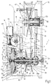
- 1 indicates as a whole a variable-ratio transmission unit comprising a clutch 2, the intake unit of which is a flywheel 3, which is integral with a drive shaft 4 of the vehicle, an intermediate shaft 5 with an axis A, which can receive motion from the clutch 2, an output shaft 6 with an axis B which is parallel to the axis A, and a pair of belt-type transmissions 7, 8, respectively with a variable and a fixed transmission ratio, which are interposed in parallel with one another, between the intermediate shaft 5 and the output shaft 6.
- the intermediate shaft 5 is supported at its own ends 9, 10 by respective bearings 11, 12, which are accommodated respectively in a support ring 13 which is integral with the flywheel 3, and in a wall 14 of a casing 15, which accommodates the transmission unit 1.
- the intermediate shaft 5 is also fitted such that it passes through a fixed tube 16 (figure 4) which is integral with the casing 15, and the function of which will be explained hereinafter.
- the clutch 2 comprises a clutch disc 20, which is connected by means of a flexible coupling 21 to a hub 22, which is integral with the intermediate shaft 5, and a disc thrust ring 23, which normally keeps the clutch disc engaged with friction against an annular surface 24 of the flywheel 3, under the thrust generated by a Belleville washer 25 of a known type.
- the spring 25 has a plurality of radial plates 26, which extend in a projecting manner towards the interior, and act as an actuating lever.
- the spring 25 is connected axially in a two-way manner to a housing 27 which is integral with the flywheel 3, at an intermediate annular end 28 of the latter, thus substantially defining a fulcrum for the resilient deformations of the spring itself.
- the clutch 2 is controlled by a first annular thrust unit 30, which slides axially along an end portion of the tube 16, by means of a thrust bearing 31.
- the thrust unit 30 is mobile axially between a position of rest, illustrated in figure 1, in which it co-operates axially against a stop 32 which is secured to the tube 16, beneath the thrust of the spring 25, towards a position of release, not shown (displaced to the left with reference to figure 1), in which it acts on the plates 26 of the spring 25, thus unloading the clutch disc 20, by means of the above-described intermediate support.
- variable-ratio transmission 7 comprises a drive pulley 34 which is supported by the intermediate shaft 5, and is integral in rotation with the latter, a driven pulley 35 which is supported by the output shaft 6, and is integral in rotation with the latter, and a trapezoidal belt 35, which is wound around the said pulleys.
- the drive pulley 34 consists of a fixed half-pulley 37, which has a hub 38 keyed onto the intermediate shaft 5, in the vicinity of the end 10 of the latter, and a conical flange 39 which can co-operate by means of friction with a side 36a of the belt 36, as well as of a mobile half-pulley 40, which has a hub 41 which is secured angularly, and can slide axially on the intermediate shaft 5, and a conical flange 42 which faces the flange 39, and can co-operate by means of friction with an opposite side 36b of the belt 36.
- the driven pulley 35 consists of a fixed half-pulley 47, which has a hub 48 keyed onto the output shaft 6, and a conical flange 49 which can co-operate by means of friction with the side 36b of the belt 36, as well as of a mobile half-pulley 50, which has a hub 51 which is secured angularly onto the hub 48 of the fixed half-pulley 47, and can slide axially on the latter, and a conical flange 52 which faces the flange 49, and can co-operate by means of friction with the side 36a of the belt 36.
- the mobile half-pulley 50 is thrust axially by a spring 53, in the direction which tends to bring the flange 52 towards the flange 49.
- the fixed-ratio transmission 8 comprises a toothed drive pulley 54, which is integral with the hub 38 of the fixed, drive half-pulley 37 of the variable-ratio transmission, and is thus integral in rotation with the intermediate shaft 5, a toothed, driven pulley 55, which is fitted onto the hub 48, with interposition of a free wheel 56 which can permit one-way transmission of torque from the pulley 55 to the hub 48, but not vice versa, and a toothed belt 57, which engages with the pulleys 27, 28.
- the pulley 55 defines an axial shoulder for the spring 53.
- the transmission ratio of the transmission 7 is controlled by the axial position of a second thrust unit 58, which slides axially on the tube 16, and can co-operate axially with the mobile half-pulley 40, with interposition of a thrust bearing 59, such as to vary the relative distance between the flanges 39, 42 of the drive pulley 34, and thus the radius of winding of the belt 36.
- a second thrust unit 58 which slides axially on the tube 16, and can co-operate axially with the mobile half-pulley 40, with interposition of a thrust bearing 59, such as to vary the relative distance between the flanges 39, 42 of the drive pulley 34, and thus the radius of winding of the belt 36.
- the first and the second thrust units 30, 58 are controlled by a single, electrically actuated control device 65.
- the control device 65 substantially comprises an electric motor 66 and a rocker-lever control unit 67 (figure 3), which is pivoted on a pin 68 which is fixed relative to the casing 15, and has an axis C which is at right-angles relative to the plane determined by the axes A and B;
- the control unit 67 is provided with a first arm 69, which is actuated by the electric motor 66, via a kinematic mechanism 70 which is described in detail hereinafter, and with a second arm 71, which has a forked end 72 (figure 4), which clasps the tube 16, and is interposed between the said thrust units 30, 58, such as to co-operate with both, by means of respective cam-type head surfaces (figure 3), in its own intermediate operative position illustrated in figure 1.
- the kinematic mechanism 70 substantially comprises an endless wheel 73, which is actuated directly by the electric motor 66, and a return component 74, which is pivoted around a pin 75 with an axis D which is parallel to the axis C;
- the return component 74 (figures 1 and 2) comprises integrally a toothed segment 75, with an angular amplitude which is substantially equivalent to 180°, which engages with the endless wheel 73, such as to produce rotation of the component 74 itself around the axis C, in response to rotation of the screw itself, and a circular cam 76, which is eccentric relative to the axis D, and co-operates with the first arm 69 of the control unit 67.
- the output shaft 6 is connected at its intake to a differential unit 77, which is not described in detail, since it is not part of the present invention, which also acts as a reduction unit/inverter, to the output of which there are connected the axle shafts (not illustrated) of the drive wheels of the vehicle.
- a differential unit 77 which is not described in detail, since it is not part of the present invention, which also acts as a reduction unit/inverter, to the output of which there are connected the axle shafts (not illustrated) of the drive wheels of the vehicle.
- the electric motor 66 is controlled by a control unit 80 (figure 5), which receives input signals s1, s2, s3 from a plurality of sensors for operative parameters relative to the driving conditions of the vehicle.
- these sensors can comprise a tachometric sensor 81, which is associated with any rotary unit, at a speed which is univocally correlated (for example is proportional or equivalent) to the speed of rotation of the wheels (signal s1), an acceleration sensor 82 which is associated with the accelerator pedal (not illustrated) or with the butterfly valve of the motor (signal s2), and a sensor 83 which is associated with the gear lever 84 (signal s3).
- the latter is advantageously of the type with three positions, i.e. D (forwards), N (neutral) and R (reverse).
- the control unit 67 is maintained by the motor 66, via the kinematic mechanism 68, in a position n of end of travel (of maximum rotation clockwise with reference to figure 1), in which the forked end 72 acts on the thrust unit 30, against the action of the spring 25, and keeps the clutch 2 released.
- the lever 84 is in the position D or R, but the signals s1, s2 are kept below respective pre-determined threshold values s10, s20, which correspond respectively to a condition in which the vehicle is almost at a standstill (for example at a speed of 3-4 km/h), and in which the accelerator is almost de-activated (for example at 5% of its own path).
- the control unit 80 controls the electric motor 70 such as to rotate the control unit progressively, in accordance with a relevant law of motion, towards the intermediate pick-up position S illustrated in figure 1.
- the clutch is thus engaged, and the intermediate shaft 5 rotates integrally with the flywheel 3.
- the fixed-ratio transmission 8 is active, since, for the reasons stated, there is no axial compression on the belt 36, and thus the variable-ratio transmission 7 is not transmitting torque.
- the driven pulley 55 of the transmission 8 thus tends to entrain the hub 48 and the output shaft 6 which is connected integrally to the latter; thus, in this operative condition, the free wheel 56 connects the pulley 55 integrally to the hub 48, and the pick-up takes place with the transmission ratio ⁇ f of the fixed-ratio transmission 8.
- the control unit 80 begins to actuate the variable-ratio transmission 7; the motor 70 is controlled such as to rotate the control unit 67 further clockwise, and thus to displace (towards the right with reference to figure 1) the second thrust unit 58 which acts on the mobile half-pulley 40.
- the belt 36 is thus compressed axially, such as to actuate the transmission of torque by friction between the drive pulley 34 and the belt itself, with an initial transmission ratio equivalent to ⁇ f; the transient state is particularly quick and smooth, since the power is transmitted prevalently by the fixed-ratio transmission 8 acting in parallel.
- the sequence of actions takes place in reverse order in the case of deceleration of the vehicle; in particular, if the speed drops below a pre-determined threshold value, and the accelerator pedal is not actuated, the transmission 7 is returned to the condition of maximum transmission ratio, and the clutch 2 is released.
- variable-ratio transmission 7 makes it possible to reduce the number of components, and thus the costs of the transmission unit 1, as well as to simplify the control of the latter. From a functional point of view, the combined use of a fixed-ratio transmission 8 in parallel with the variable-ratio transmission 7 makes it possible to render the transient states smooth and controllable at low speeds, and to increase considerably the life of the trapezoidal belt 36, which is not subjected to sliding in loaded conditions.
- variable-ratio transmission 7 alone can be used.
- the electric motor 66 can be controlled according to any type of logic.
- the return component 74 and the control unit 67 can be replaced by any known type of kinematic mechanism, provided that it has an output unit which can control both the thrust units 30, 58.
- the cam 75 can be produced with a profile which is not circular, and such as to vary according to a predetermined law the path of the thrust units 30, 58.
- rotation of the control unit 67 can be controlled by the electric motor, by means of a simple gearing mechanism, an output unit of which is integral in rotation with the control component 67.
Landscapes
- Engineering & Computer Science (AREA)
- Transportation (AREA)
- Mechanical Engineering (AREA)
- Chemical & Material Sciences (AREA)
- Combustion & Propulsion (AREA)
- Automation & Control Theory (AREA)
- Transmissions By Endless Flexible Members (AREA)
- Control Of Transmission Device (AREA)
- Vehicle Body Suspensions (AREA)
- Color Television Systems (AREA)
Applications Claiming Priority (2)
| Application Number | Priority Date | Filing Date | Title |
|---|---|---|---|
| ITTO990854 | 1999-10-05 | ||
| IT1999TO000854A IT1307356B1 (it) | 1999-10-05 | 1999-10-05 | Unita' di trasmissione automatica a rapporto variabile con continuita' |
Publications (1)
| Publication Number | Publication Date |
|---|---|
| EP1090802A1 true EP1090802A1 (fr) | 2001-04-11 |
Family
ID=11418117
Family Applications (1)
| Application Number | Title | Priority Date | Filing Date |
|---|---|---|---|
| EP00121692A Withdrawn EP1090802A1 (fr) | 1999-10-05 | 2000-10-04 | Transmission automatique à variation de rapport continue |
Country Status (2)
| Country | Link |
|---|---|
| EP (1) | EP1090802A1 (fr) |
| IT (1) | IT1307356B1 (fr) |
Cited By (3)
| Publication number | Priority date | Publication date | Assignee | Title |
|---|---|---|---|---|
| FR2892082A1 (fr) | 2005-10-19 | 2007-04-20 | France Reducteurs Soc Par Acti | Transmission, notamment entre un arbre moteur et un arbre d'entrainement de roues d'un engin, engin de preference automoteur equipe d'une telle transmission et son procede de commande en fonctionnement |
| CN100412413C (zh) * | 2001-09-19 | 2008-08-20 | 剩沅科技股份有限公司 | 自动施加可变转矩于以定速转动的输出轴上的驱动装置 |
| CN111801518A (zh) * | 2018-03-19 | 2020-10-20 | 北极星工业有限公司 | 具有摩擦离合器的电子cvt |
Citations (4)
| Publication number | Priority date | Publication date | Assignee | Title |
|---|---|---|---|---|
| EP0027513A1 (fr) * | 1979-09-04 | 1981-04-29 | INDUS WHEEL COMPANY Division of Carlisle | Véhicule avec dispositif de commande combinée de changement de vitesse et de direction, et appareil à cet effet |
| US4671138A (en) * | 1983-10-31 | 1987-06-09 | Mazda Motor Corporation | Speed ratio control of a steplessly variable vehicle transmission |
| US4925432A (en) * | 1987-09-25 | 1990-05-15 | Honda Giken Kogyo Kabushiki Kaisha | Belt-type continuously variable transmission and engine speed control device therefore |
| DE19723394A1 (de) * | 1996-06-05 | 1997-12-11 | Luk Getriebe Systeme Gmbh | Betätigungsvorrichtung |
-
1999
- 1999-10-05 IT IT1999TO000854A patent/IT1307356B1/it active
-
2000
- 2000-10-04 EP EP00121692A patent/EP1090802A1/fr not_active Withdrawn
Patent Citations (4)
| Publication number | Priority date | Publication date | Assignee | Title |
|---|---|---|---|---|
| EP0027513A1 (fr) * | 1979-09-04 | 1981-04-29 | INDUS WHEEL COMPANY Division of Carlisle | Véhicule avec dispositif de commande combinée de changement de vitesse et de direction, et appareil à cet effet |
| US4671138A (en) * | 1983-10-31 | 1987-06-09 | Mazda Motor Corporation | Speed ratio control of a steplessly variable vehicle transmission |
| US4925432A (en) * | 1987-09-25 | 1990-05-15 | Honda Giken Kogyo Kabushiki Kaisha | Belt-type continuously variable transmission and engine speed control device therefore |
| DE19723394A1 (de) * | 1996-06-05 | 1997-12-11 | Luk Getriebe Systeme Gmbh | Betätigungsvorrichtung |
Cited By (6)
| Publication number | Priority date | Publication date | Assignee | Title |
|---|---|---|---|---|
| CN100412413C (zh) * | 2001-09-19 | 2008-08-20 | 剩沅科技股份有限公司 | 自动施加可变转矩于以定速转动的输出轴上的驱动装置 |
| FR2892082A1 (fr) | 2005-10-19 | 2007-04-20 | France Reducteurs Soc Par Acti | Transmission, notamment entre un arbre moteur et un arbre d'entrainement de roues d'un engin, engin de preference automoteur equipe d'une telle transmission et son procede de commande en fonctionnement |
| FR2892080A1 (fr) * | 2005-10-19 | 2007-04-20 | France Reducteurs Sas Soc Par | Transmission, notamment entre un arbre moteur et un arbre d'entrainement de roues d'un engin, de preference automoteur, et engin de preference automoteur equipe d'une telle transmission |
| US7641580B2 (en) | 2005-10-19 | 2010-01-05 | France Reducteurs | Transmission |
| CN111801518A (zh) * | 2018-03-19 | 2020-10-20 | 北极星工业有限公司 | 具有摩擦离合器的电子cvt |
| CN111801518B (zh) * | 2018-03-19 | 2023-10-31 | 北极星工业有限公司 | 具有摩擦离合器的电子cvt |
Also Published As
| Publication number | Publication date |
|---|---|
| ITTO990854A1 (it) | 2001-04-05 |
| IT1307356B1 (it) | 2001-11-06 |
Similar Documents
| Publication | Publication Date | Title |
|---|---|---|
| US8770327B2 (en) | Accessory drive mechanism for hybrid vehicle | |
| US7309067B2 (en) | Continuously variable transmission | |
| US20090042678A1 (en) | Reversible driven pulley for a continuously variable transmission | |
| EP0851149B1 (fr) | Engrenage planétaire | |
| US11592100B2 (en) | Uniform clamp actuated shift infinitely variable transmission system | |
| US7235035B2 (en) | Release clutch for a vehicle | |
| JP2747803B2 (ja) | ベルト式自動変速機 | |
| RU2440524C1 (ru) | Адаптивная трансмиссия для транспортного средства | |
| RU188664U1 (ru) | Цепной редуктор с реверсом | |
| JP4941819B2 (ja) | デフギア装置のデフロック機構 | |
| US8105190B2 (en) | Pulley assembly with an improved clutch for a continuously variable transmission | |
| JP6307486B2 (ja) | 車両の制御装置 | |
| JP3162328B2 (ja) | 車載用vベルト式自動変速機 | |
| US12110951B2 (en) | Double clutch reverse and active torque management system | |
| US6666789B2 (en) | Frictional variable transmission for vehicle | |
| RU2333405C1 (ru) | Регулятор оборотов двигателя транспортного средства с преобразователем передаточного отношения трансмиссии, зависящим от нагрузки на выходном валу | |
| US4637270A (en) | Arrangement for governing vehicle engine speed responsive to actual running speed of the vehicle | |
| ITTO990854A1 (it) | Unita' di trasmissione automatica a rapporto variabile con continuita'. | |
| JP2005164014A (ja) | トロイダル型無段変速装置 | |
| JP2918878B1 (ja) | 自動車用無段変速機 | |
| US942912A (en) | Speed-changing mechanism. | |
| US797240A (en) | Reversing and change-speed clutch mechanism. | |
| JP6575375B2 (ja) | 無段変速装置 | |
| JP3096590B2 (ja) | 作業車の変速装置 | |
| JP6575377B2 (ja) | 無段変速装置 |
Legal Events
| Date | Code | Title | Description |
|---|---|---|---|
| PUAI | Public reference made under article 153(3) epc to a published international application that has entered the european phase |
Free format text: ORIGINAL CODE: 0009012 |
|
| AK | Designated contracting states |
Kind code of ref document: A1 Designated state(s): AT BE CH CY DE DK ES FI FR GB GR IE IT LI LU MC NL PT SE |
|
| AX | Request for extension of the european patent |
Free format text: AL;LT;LV;MK;RO;SI |
|
| 17P | Request for examination filed |
Effective date: 20011009 |
|
| AKX | Designation fees paid |
Free format text: AT BE CH CY DE DK ES FI FR GB GR IE IT LI LU MC NL PT SE |
|
| 17Q | First examination report despatched |
Effective date: 20021217 |
|
| STAA | Information on the status of an ep patent application or granted ep patent |
Free format text: STATUS: THE APPLICATION IS DEEMED TO BE WITHDRAWN |
|
| 18D | Application deemed to be withdrawn |
Effective date: 20030628 |