EP1090837A2 - Notrutsche - Google Patents
Notrutsche Download PDFInfo
- Publication number
- EP1090837A2 EP1090837A2 EP00121719A EP00121719A EP1090837A2 EP 1090837 A2 EP1090837 A2 EP 1090837A2 EP 00121719 A EP00121719 A EP 00121719A EP 00121719 A EP00121719 A EP 00121719A EP 1090837 A2 EP1090837 A2 EP 1090837A2
- Authority
- EP
- European Patent Office
- Prior art keywords
- escape slide
- slide
- set forth
- escape
- life raft
- Prior art date
- Legal status (The legal status is an assumption and is not a legal conclusion. Google has not performed a legal analysis and makes no representation as to the accuracy of the status listed.)
- Granted
Links
- 239000000463 material Substances 0.000 claims abstract description 5
- XLYOFNOQVPJJNP-UHFFFAOYSA-N water Substances O XLYOFNOQVPJJNP-UHFFFAOYSA-N 0.000 claims description 7
- 238000005192 partition Methods 0.000 claims description 6
- 230000002093 peripheral effect Effects 0.000 claims description 6
- 230000001154 acute effect Effects 0.000 claims description 3
- 230000002787 reinforcement Effects 0.000 claims 1
- 238000010276 construction Methods 0.000 description 3
- 230000002411 adverse Effects 0.000 description 2
- 238000004891 communication Methods 0.000 description 2
- 239000012530 fluid Substances 0.000 description 2
- 230000033001 locomotion Effects 0.000 description 2
- 230000004308 accommodation Effects 0.000 description 1
- 239000000853 adhesive Substances 0.000 description 1
- 230000001070 adhesive effect Effects 0.000 description 1
- 238000005452 bending Methods 0.000 description 1
- 230000005465 channeling Effects 0.000 description 1
- 239000002131 composite material Substances 0.000 description 1
- 230000026058 directional locomotion Effects 0.000 description 1
- 238000006073 displacement reaction Methods 0.000 description 1
- 229920001971 elastomer Polymers 0.000 description 1
- 239000000806 elastomer Substances 0.000 description 1
- 239000004744 fabric Substances 0.000 description 1
- 238000012986 modification Methods 0.000 description 1
- 230000004048 modification Effects 0.000 description 1
- 230000037361 pathway Effects 0.000 description 1
- 239000003643 water by type Substances 0.000 description 1
Images


Classifications
-
- B—PERFORMING OPERATIONS; TRANSPORTING
- B64—AIRCRAFT; AVIATION; COSMONAUTICS
- B64D—EQUIPMENT FOR FITTING IN OR TO AIRCRAFT; FLIGHT SUITS; PARACHUTES; ARRANGEMENT OR MOUNTING OF POWER PLANTS OR PROPULSION TRANSMISSIONS IN AIRCRAFT
- B64D25/00—Emergency apparatus or devices, not otherwise provided for
- B64D25/08—Ejecting or escaping means
- B64D25/14—Inflatable escape chutes
Definitions
- This invention relates to an inflatable life raft escape slide for aircraft and more particularly to a new and improved escape slide for use in evacuating passengers from especially high exits as well as those portions of an aircraft that have external obstructions.
- a porch type structure is used as part of the inflatable slide that is situated adjacent to the aircraft body.
- the porch inflatable portion of the slide which is horizontal, provides a turn in direction from the exit door to that portion of the inflatable slide that evacuates the passengers away from the aircraft.
- the present invention is directed to a structural design of an inflatable escape slide that accommodates the location of the egress door and openings as needed by design even where there are external obstructions by the use of an inflatable escape slide that has a curvilinear portion, which curvilinear portion may be located near the egress door or further along the escape slide. It is the curvilinear portion that avoids the design obstructions such as wing configurations and nacelles for aircraft engines.
- the escape slide of the present invention utilizes a double septum chambered construction which permits its use on aircraft structures that require slides of greater overall length since aircraft are larger in construction, height, width and accommodations.
- the double septum chambers provide greater strength with greater resistance to deformation forces.
- An aircraft inflatable life raft escape slide for use from an elevated structure such as an aircraft where such inflatable escape slide is deployable from an egress opening having its head end at such elevated openings and a toe end, upon deployment, located adjacent the ground level.
- the escape slide has an upper sliding surface with a longitudinally extending center line and with a portion of such escape slide being curvilinear in plan view to facilitate its deployment where there are obstructions such as the wing portions of an aircraft and its engine nacelles. This structure permits the aircraft design to accommodate the proper spacing of escape slides along it entire length.
- the escape slide has the curvilinear portion skewed to enhance the safe movement along the slides's length at the curvilinear portion as there is a change in directional movement of the evacuee, otherwise there is a continual movement in the same direction by the law of physics.
- This structure is thus extremely useful in view of the fact that aircraft structures have become increasingly larger and it is necessary to take into consideration the increased speeds that occur in evacuating passengers from these increased elevated structures.
- the escape slide is also provided with a double septum chamber structure to increase its resistance to deformation under load and adverse weather conditions.
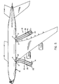
- FIGs. 1 and 2 an inflatable life raft escape slide 10 deployed from an egress door 11 of an aircraft fuselage 12 to the surface of the ground 14 so that passengers may safely slide down the slide 10 from the aircraft to the ground 14.
- the escape slide 10 is releasably fastened to the fuselage 12 by a girt bar 15 that is located adjacent to the egress door 11, which girt bar 15 is secured to spaced brackets 16 in a manner old and well known in the art.
- a positioning tube 17, which is connected to the escape slide 10 is located between the slide 10 and the fuselage 12 to aid in the positive positioning of the escape slide during deployment.
- the inflation system includes a source of high pressure fluid as container 19 which is suitably secured to the escape slide and upon actuation delivers pressurized fluids to an aspirator 20 or aspirators for pressurizing the escape slide 10 and the positioning tube 17.
- the escape slide 10 has a head end 21 and a toe end 22.
- the entire escape slide 10 is fabricated from a fabric of suitable material and coated with an elastomer.
- the various parts of the escape slide 10 are joined together with a suitable adhesive whereby the composite structure to be described will permit air flow to the various internal chambers via suitable passageways but will preclude the air flow externally from the various chambers in the inflated condition.
- the escape slide 10 has an upper longitudinally extending panel or panel member 25 and a lower longitudinally extending panel or panel member 26 that are suitably connected at their respective sides in a manner to be described.
- Slide 10 also includes a plurality of longitudinally extending flexible partitions or bulkheads 30, 31, 32, 33, 34, 35, 36 and 37 that extend along the inside thereof and are suitably adhered along their respective running edges to the upper panel member 25 and the lower panel member 26.
- the respective bulkheads 30 and 37 are slanted inwardly and upwardly relative to a longitudinal center line of the escape slide which center line is designated 38 in Fig. 4.
- the respective partitions 33 and 34 are slanted outwardly and upwardly relative to the center line 38.
- the remaining bulkheads extend in a general vertical direction.
- the load forces imparted by the passengers on the upper panel 25 distributes the forces with less distortion of the tubes or chambers as formed by the bulkheads.
- the chambers formed by the use of the partitions 30 through 37 with the upper panel 25 and the lower panel 26 are all in communication with each other to facilitate the inflation of all the chambers.
- the upper panel 25 and the lower panel 26 cooperate with the bulkheads 30 through 37 to create a series of longitudinally extending chambers which are in suitable communication with each other.
- the chambers are indicated as 1, through 9.
- the center chamber 5 is fabricated to have a higher crown to thereby provide a raised portion to separate the sliding surface of the upper panel 25 into two sliding pathways.
- the upper panel 25 is composed of three panel sections (as shown in Fig. 4) A, B and C respectively. As seen in plan view sections A and C are linear in plan view whereas section B is curvilinear. Section A may be much shorter in length than section C, thus placing the curvilinear section B close to the egress door 11 of the aircraft as shown in Fig. 5.
- Fig. 4 shows the upper panel's edge section as having an inner peripheral radius of curvature of R-1 whereas the lower panel's edge section B as having an inner peripheral radius of curvature of R-2 wherein R-2 is greater than R-1.
- the surface or the sliding surface of the escape slide at the curvilinear portion is skewed inwardly considering the outer periphery to the inner periphery of this section, which is along section B of the upper panel 25.
- This skewing can also be achieved by other means as by making panel 26 of greater width at the curvature.
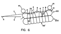
- FIG. 3 The above described structure of the upper panel 25, lower panel 26 and the bulkheads 30 through 37 form an elongated or longitudinally extending upper flexible septum chamber which in Fig. 3 is designated by the numeral 100.
- Substantially coextensive in length with the upper septum structure or chamber is an elongated or longitudinally extending lower flexible septum structure or septum chamber 200 which septum chamber 200 is substantially identical in construction to the upper septum chamber 100.
- Lower septum structure 200 has its own upper panel 25', and lower panel 26' along with its own bulkheads 30', 31', 32', 33', 34', 35', 36' and 37' thus providing a plurality of tubular members.
- Inflatable guide rail bumpers or tubes 41 are suitably bonded at the upper respective margins of the escape slide as shown in Figs. 1, 2, 3 and 5.
- a particular advantage of using an upper septum chamber 100 and a lower septum chamber 200 is that such structures improve bending resistance characteristics over conventional stacked "round" tubes structures with their trusses.
- the septum structure minimizes lateral deflection of the escape slide under strong wind conditions while maximizing the overall beam strength for use in large scale aircraft.
- a further advantage of using the double stacked septum chamber structure is that when used as a slide raft in the ditching mode, the increased size and volume of the lower septum chamber results in a higher raft above the critical water level in high waters with loaded passengers since there is a lower displacement depth in the water (because the lower septum chamber is pressurized and makes the upper septum chamber side higher in the water).
Landscapes
- Business, Economics & Management (AREA)
- Emergency Management (AREA)
- Engineering & Computer Science (AREA)
- Aviation & Aerospace Engineering (AREA)
- Emergency Lowering Means (AREA)
- Tires In General (AREA)
- Aiming, Guidance, Guns With A Light Source, Armor, Camouflage, And Targets (AREA)
Applications Claiming Priority (2)
| Application Number | Priority Date | Filing Date | Title |
|---|---|---|---|
| US413838 | 1989-09-28 | ||
| US09/413,838 US6471001B1 (en) | 1999-10-06 | 1999-10-06 | Escape slide |
Publications (3)
| Publication Number | Publication Date |
|---|---|
| EP1090837A2 true EP1090837A2 (de) | 2001-04-11 |
| EP1090837A3 EP1090837A3 (de) | 2001-07-25 |
| EP1090837B1 EP1090837B1 (de) | 2004-12-22 |
Family
ID=23638865
Family Applications (1)
| Application Number | Title | Priority Date | Filing Date |
|---|---|---|---|
| EP00121719A Expired - Lifetime EP1090837B1 (de) | 1999-10-06 | 2000-10-05 | Notrutsche |
Country Status (4)
| Country | Link |
|---|---|
| US (2) | US6471001B1 (de) |
| EP (1) | EP1090837B1 (de) |
| JP (1) | JP2001171598A (de) |
| DE (1) | DE60016868T2 (de) |
Cited By (4)
| Publication number | Priority date | Publication date | Assignee | Title |
|---|---|---|---|---|
| EP1431178A1 (de) * | 2002-12-19 | 2004-06-23 | Goodrich Corporation | Notrutsche mit Spoiler an der Anströmkante |
| WO2017148703A1 (de) * | 2016-03-03 | 2017-09-08 | Siemens Ag Österreich | Evakuierungseinrichtung |
| CN107826233A (zh) * | 2016-09-15 | 2018-03-23 | 古德里奇公司 | 用于疏散滑梯系统的拱形可充气结构 |
| RU240963U1 (ru) * | 2025-02-05 | 2026-01-30 | Любовь Викторовна Глотова | Трап эвакуационный |
Families Citing this family (20)
| Publication number | Priority date | Publication date | Assignee | Title |
|---|---|---|---|---|
| US6231483B1 (en) * | 1999-06-24 | 2001-05-15 | Forrest B. Phillips | Sliding exercise apparatus and recreational device |
| US6966414B2 (en) * | 2003-12-02 | 2005-11-22 | Goodrich Corporation | Elevated inflatable emergency evacuation slide illumination |
| US7789761B1 (en) * | 2005-06-09 | 2010-09-07 | Piper Lumsden | Recreational stairway slide |
| US7494419B2 (en) * | 2006-01-11 | 2009-02-24 | Dov Katz | Indoor stair slide for transporting the handicapped between floors and/or for joyful rides |
| GB0609892D0 (en) * | 2006-05-18 | 2006-06-28 | Airbus Uk Ltd | Aircraft walkway |
| GB0709969D0 (en) * | 2007-05-24 | 2007-07-04 | Airbus Uk Ltd | Improvements in unloading and loading of aircraft |
| US9162735B2 (en) * | 2008-08-28 | 2015-10-20 | Michael Grainger | Inflatable evacuation slide |
| JP2015012972A (ja) * | 2013-07-04 | 2015-01-22 | 株式会社シーエス | 可搬式シュート |
| US10000291B2 (en) * | 2015-09-24 | 2018-06-19 | Goodrich Corporation | Aircraft evacuation slide |
| US10118708B2 (en) * | 2015-10-19 | 2018-11-06 | Goodrich Corporation | Evacuation slide with beam structure comprising four-point cross section |
| US10549861B2 (en) * | 2016-11-14 | 2020-02-04 | Goodrich Corporation | Redundant layer for inflatable evacuation component |
| US10464682B2 (en) * | 2017-01-06 | 2019-11-05 | Goodrich Corporation | Negative lift evacuation slide |
| US10611489B2 (en) | 2017-05-24 | 2020-04-07 | Goodrich Corporation | Evacuation system with an extendable head end |
| US11345478B2 (en) * | 2019-09-26 | 2022-05-31 | Goodrich Corporation | Evacuation slide and method of forming evacuation slide having integral cable channel |
| US11390391B2 (en) * | 2020-03-19 | 2022-07-19 | Goodrich Corporation | Evacuee-centering evacuation slide |
| US20220196181A1 (en) * | 2020-12-23 | 2022-06-23 | Goodrich Corporation | Inflatable systems with electro-pneumatic valve modules |
| US12534210B2 (en) | 2021-12-17 | 2026-01-27 | Goodrich Corporation | Stacked inflatable tubes and methods of forming stacked inflatable tubes for evacuation assemblies |
| EP4197914B1 (de) * | 2021-12-17 | 2025-10-08 | Goodrich Corporation | Gestapelte aufblasbare schläuche und verfahren zum bilden gestapelter aufblasbarer schläuche für evakuierungsbaugruppen |
| US12139263B2 (en) * | 2022-05-02 | 2024-11-12 | Goodrich Corporation | Inflatable girt for evacuation slide |
| WO2025012136A1 (en) * | 2023-07-07 | 2025-01-16 | Viking Life-Saving Equipment A/S | An inflatable evacuation slide |
Family Cites Families (18)
| Publication number | Priority date | Publication date | Assignee | Title |
|---|---|---|---|---|
| US1596552A (en) * | 1924-01-16 | 1926-08-17 | Frank M Potter | Fire escape |
| FR96018E (fr) * | 1967-10-23 | 1972-05-19 | Goodrich Co B F | Glissiere pneumatique de sauvetage. |
| US3692144A (en) * | 1970-11-18 | 1972-09-19 | Garrett Corp | Fluid distensible truss |
| US3819011A (en) * | 1971-10-19 | 1974-06-25 | Mitsubishi Electric Corp | Inflatable escape slideway apparatus |
| US3771749A (en) * | 1973-01-05 | 1973-11-13 | Garrett Corp | Emergency aircraft evacuation apparatus and method |
| US3829353A (en) * | 1973-03-21 | 1974-08-13 | J Fisher | Method of making inflatable assembly with bulkheads and resulting article |
| US3910377A (en) * | 1974-08-08 | 1975-10-07 | Lawrence Peska Ass Inc | Life saving escape chute |
| US3973645A (en) * | 1975-08-15 | 1976-08-10 | The Garrett Corporation | Inflatable evacuation slide |
| US4018321A (en) | 1976-05-21 | 1977-04-19 | The B. F. Goodrich Company | Escape slide and platform assembly |
| US4333546A (en) * | 1980-02-19 | 1982-06-08 | The B. F. Goodrich Company | Escape slide |
| SE445889B (sv) * | 1980-05-05 | 1986-07-28 | Schwamm Horst | Rull- eller glidbana for ostyrda akdon |
| US4487411A (en) * | 1980-09-02 | 1984-12-11 | Miracle Recreation Equipment Company | Playground tube slide |
| US4434870A (en) | 1982-11-22 | 1984-03-06 | The B. F. Goodrich Company | Evacuation slide device |
| US4846422A (en) * | 1984-05-14 | 1989-07-11 | The Bfgoodrich Company | Single piece evacuation system for aircraft or the like |
| US4684079A (en) | 1985-12-13 | 1987-08-04 | The Garrett Corporation | Inflatable evacuation device |
| US5150765A (en) | 1991-08-08 | 1992-09-29 | Chen Yen Huang | Fire escape |
| SE468992B (sv) | 1992-04-16 | 1993-04-26 | Trelleborg Ind Ab | Uppblaasbar bro, saerskilt raeddningsbro, samt slang foer uppstyvning av denna |
| US5975467A (en) * | 1998-08-06 | 1999-11-02 | Air Cruisers Company | Inflatable evacuation slide |
-
1999
- 1999-10-06 US US09/413,838 patent/US6471001B1/en not_active Expired - Lifetime
-
2000
- 2000-10-05 EP EP00121719A patent/EP1090837B1/de not_active Expired - Lifetime
- 2000-10-05 DE DE60016868T patent/DE60016868T2/de not_active Expired - Lifetime
- 2000-10-05 JP JP2000305590A patent/JP2001171598A/ja not_active Withdrawn
-
2002
- 2002-04-09 US US10/120,076 patent/US6698545B2/en not_active Expired - Lifetime
Non-Patent Citations (1)
| Title |
|---|
| None |
Cited By (7)
| Publication number | Priority date | Publication date | Assignee | Title |
|---|---|---|---|---|
| EP1431178A1 (de) * | 2002-12-19 | 2004-06-23 | Goodrich Corporation | Notrutsche mit Spoiler an der Anströmkante |
| US6877696B2 (en) | 2002-12-19 | 2005-04-12 | Goodrich Corporation | Evacuation slide with leading edge spoiler |
| WO2017148703A1 (de) * | 2016-03-03 | 2017-09-08 | Siemens Ag Österreich | Evakuierungseinrichtung |
| CN108698615A (zh) * | 2016-03-03 | 2018-10-23 | 奥地利西门子公司 | 疏散装置 |
| CN107826233A (zh) * | 2016-09-15 | 2018-03-23 | 古德里奇公司 | 用于疏散滑梯系统的拱形可充气结构 |
| CN107826233B (zh) * | 2016-09-15 | 2022-05-10 | 古德里奇公司 | 用于疏散滑梯系统的拱形可充气结构 |
| RU240963U1 (ru) * | 2025-02-05 | 2026-01-30 | Любовь Викторовна Глотова | Трап эвакуационный |
Also Published As
| Publication number | Publication date |
|---|---|
| US20020117354A1 (en) | 2002-08-29 |
| JP2001171598A (ja) | 2001-06-26 |
| EP1090837A3 (de) | 2001-07-25 |
| US6471001B1 (en) | 2002-10-29 |
| EP1090837B1 (de) | 2004-12-22 |
| US6698545B2 (en) | 2004-03-02 |
| DE60016868T2 (de) | 2005-12-08 |
| DE60016868D1 (de) | 2005-01-27 |
Similar Documents
| Publication | Publication Date | Title |
|---|---|---|
| US6471001B1 (en) | Escape slide | |
| US5975467A (en) | Inflatable evacuation slide | |
| US4018321A (en) | Escape slide and platform assembly | |
| CA1218612A (en) | Evacuation slide device | |
| US5360186A (en) | Inflatable slide raft assembly | |
| US4246980A (en) | Evacuation slide deceleration | |
| US4519782A (en) | Escape slide and life raft | |
| US3507466A (en) | Aircraft undercarriage | |
| EP0034358B1 (de) | Notrutsche und Rettungsfloss | |
| EP0893343A2 (de) | Aufblasbare Notrutsch-Einrichtung | |
| EP0864493A2 (de) | Notrutsche mit Tragrohrvorrichtung | |
| US5112011A (en) | Pneumatic deicer for shedding thin ice | |
| EP1431178B1 (de) | Notrutsche mit Spoiler an der Anströmkante | |
| AU2005202548B2 (en) | An inflatable boat with an high pressure inflatable keel | |
| US3692144A (en) | Fluid distensible truss | |
| EP0184745B1 (de) | Notrutsche | |
| US9162735B2 (en) | Inflatable evacuation slide | |
| US4351500A (en) | Ski/float landing gear apparatus for aircraft | |
| DE3829617C2 (de) | ||
| US3464515A (en) | Inflatable escape chutes for aircraft | |
| US10822098B2 (en) | Evacuation system inflatable toe end spring and sill height compensating feature | |
| US3726375A (en) | Inflated escape ramps | |
| WO2004020284A2 (en) | Wing structure | |
| US20210291993A1 (en) | Evacuee-centering evacuation slide | |
| JP2003514713A (ja) | 軽量および超軽量航空機用の空気圧フロート |
Legal Events
| Date | Code | Title | Description |
|---|---|---|---|
| PUAI | Public reference made under article 153(3) epc to a published international application that has entered the european phase |
Free format text: ORIGINAL CODE: 0009012 |
|
| AK | Designated contracting states |
Kind code of ref document: A2 Designated state(s): DE FR |
|
| AX | Request for extension of the european patent |
Free format text: AL;LT;LV;MK;RO;SI |
|
| PUAL | Search report despatched |
Free format text: ORIGINAL CODE: 0009013 |
|
| AK | Designated contracting states |
Kind code of ref document: A3 Designated state(s): AT BE CH CY DE DK ES FI FR GB GR IE IT LI LU MC NL PT SE |
|
| AX | Request for extension of the european patent |
Free format text: AL;LT;LV;MK;RO;SI |
|
| 17P | Request for examination filed |
Effective date: 20020117 |
|
| AKX | Designation fees paid |
Free format text: DE FR |
|
| RAP1 | Party data changed (applicant data changed or rights of an application transferred) |
Owner name: GOODRICH CORPORATION |
|
| 17Q | First examination report despatched |
Effective date: 20030507 |
|
| GRAP | Despatch of communication of intention to grant a patent |
Free format text: ORIGINAL CODE: EPIDOSNIGR1 |
|
| GRAS | Grant fee paid |
Free format text: ORIGINAL CODE: EPIDOSNIGR3 |
|
| GRAA | (expected) grant |
Free format text: ORIGINAL CODE: 0009210 |
|
| AK | Designated contracting states |
Kind code of ref document: B1 Designated state(s): DE FR |
|
| REF | Corresponds to: |
Ref document number: 60016868 Country of ref document: DE Date of ref document: 20050127 Kind code of ref document: P |
|
| PLBE | No opposition filed within time limit |
Free format text: ORIGINAL CODE: 0009261 |
|
| STAA | Information on the status of an ep patent application or granted ep patent |
Free format text: STATUS: NO OPPOSITION FILED WITHIN TIME LIMIT |
|
| ET | Fr: translation filed | ||
| 26N | No opposition filed |
Effective date: 20050923 |
|
| REG | Reference to a national code |
Ref country code: FR Ref legal event code: PLFP Year of fee payment: 17 |
|
| REG | Reference to a national code |
Ref country code: FR Ref legal event code: PLFP Year of fee payment: 18 |
|
| REG | Reference to a national code |
Ref country code: FR Ref legal event code: PLFP Year of fee payment: 19 |
|
| PGFP | Annual fee paid to national office [announced via postgrant information from national office to epo] |
Ref country code: FR Payment date: 20190919 Year of fee payment: 20 |
|
| PGFP | Annual fee paid to national office [announced via postgrant information from national office to epo] |
Ref country code: DE Payment date: 20190918 Year of fee payment: 20 |
|
| REG | Reference to a national code |
Ref country code: DE Ref legal event code: R071 Ref document number: 60016868 Country of ref document: DE |