EP1091178A2 - Klimaanlage für mehrere Räume und Steuerverfahren hierfür - Google Patents
Klimaanlage für mehrere Räume und Steuerverfahren hierfür Download PDFInfo
- Publication number
- EP1091178A2 EP1091178A2 EP00116247A EP00116247A EP1091178A2 EP 1091178 A2 EP1091178 A2 EP 1091178A2 EP 00116247 A EP00116247 A EP 00116247A EP 00116247 A EP00116247 A EP 00116247A EP 1091178 A2 EP1091178 A2 EP 1091178A2
- Authority
- EP
- European Patent Office
- Prior art keywords
- temperature
- control
- piping
- indoor
- indoor unit
- Prior art date
- Legal status (The legal status is an assumption and is not a legal conclusion. Google has not performed a legal analysis and makes no representation as to the accuracy of the status listed.)
- Granted
Links
Images








Classifications
-
- F—MECHANICAL ENGINEERING; LIGHTING; HEATING; WEAPONS; BLASTING
- F25—REFRIGERATION OR COOLING; COMBINED HEATING AND REFRIGERATION SYSTEMS; HEAT PUMP SYSTEMS; MANUFACTURE OR STORAGE OF ICE; LIQUEFACTION SOLIDIFICATION OF GASES
- F25B—REFRIGERATION MACHINES, PLANTS OR SYSTEMS; COMBINED HEATING AND REFRIGERATION SYSTEMS; HEAT PUMP SYSTEMS
- F25B49/00—Arrangement or mounting of control or safety devices
- F25B49/02—Arrangement or mounting of control or safety devices for compression type machines, plants or systems
- F25B49/022—Compressor control arrangements
-
- F—MECHANICAL ENGINEERING; LIGHTING; HEATING; WEAPONS; BLASTING
- F24—HEATING; RANGES; VENTILATING
- F24F—AIR-CONDITIONING; AIR-HUMIDIFICATION; VENTILATION; USE OF AIR CURRENTS FOR SCREENING
- F24F11/00—Control or safety arrangements
- F24F11/70—Control systems characterised by their outputs; Constructional details thereof
- F24F11/72—Control systems characterised by their outputs; Constructional details thereof for controlling the supply of treated air, e.g. its pressure
- F24F11/79—Control systems characterised by their outputs; Constructional details thereof for controlling the supply of treated air, e.g. its pressure for controlling the direction of the supplied air
-
- F—MECHANICAL ENGINEERING; LIGHTING; HEATING; WEAPONS; BLASTING
- F24—HEATING; RANGES; VENTILATING
- F24F—AIR-CONDITIONING; AIR-HUMIDIFICATION; VENTILATION; USE OF AIR CURRENTS FOR SCREENING
- F24F11/00—Control or safety arrangements
- F24F11/30—Control or safety arrangements for purposes related to the operation of the system, e.g. for safety or monitoring
- F24F11/46—Improving electric energy efficiency or saving
-
- F—MECHANICAL ENGINEERING; LIGHTING; HEATING; WEAPONS; BLASTING
- F24—HEATING; RANGES; VENTILATING
- F24F—AIR-CONDITIONING; AIR-HUMIDIFICATION; VENTILATION; USE OF AIR CURRENTS FOR SCREENING
- F24F11/00—Control or safety arrangements
- F24F11/50—Control or safety arrangements characterised by user interfaces or communication
- F24F11/56—Remote control
-
- F—MECHANICAL ENGINEERING; LIGHTING; HEATING; WEAPONS; BLASTING
- F24—HEATING; RANGES; VENTILATING
- F24F—AIR-CONDITIONING; AIR-HUMIDIFICATION; VENTILATION; USE OF AIR CURRENTS FOR SCREENING
- F24F11/00—Control or safety arrangements
- F24F11/62—Control or safety arrangements characterised by the type of control or by internal processing, e.g. using fuzzy logic, adaptive control or estimation of values
- F24F11/63—Electronic processing
- F24F11/64—Electronic processing using pre-stored data
-
- F—MECHANICAL ENGINEERING; LIGHTING; HEATING; WEAPONS; BLASTING
- F24—HEATING; RANGES; VENTILATING
- F24F—AIR-CONDITIONING; AIR-HUMIDIFICATION; VENTILATION; USE OF AIR CURRENTS FOR SCREENING
- F24F11/00—Control or safety arrangements
- F24F11/70—Control systems characterised by their outputs; Constructional details thereof
- F24F11/72—Control systems characterised by their outputs; Constructional details thereof for controlling the supply of treated air, e.g. its pressure
- F24F11/74—Control systems characterised by their outputs; Constructional details thereof for controlling the supply of treated air, e.g. its pressure for controlling air flow rate or air velocity
- F24F11/76—Control systems characterised by their outputs; Constructional details thereof for controlling the supply of treated air, e.g. its pressure for controlling air flow rate or air velocity by means responsive to temperature, e.g. bimetal springs
-
- F—MECHANICAL ENGINEERING; LIGHTING; HEATING; WEAPONS; BLASTING
- F24—HEATING; RANGES; VENTILATING
- F24F—AIR-CONDITIONING; AIR-HUMIDIFICATION; VENTILATION; USE OF AIR CURRENTS FOR SCREENING
- F24F11/00—Control or safety arrangements
- F24F11/70—Control systems characterised by their outputs; Constructional details thereof
- F24F11/72—Control systems characterised by their outputs; Constructional details thereof for controlling the supply of treated air, e.g. its pressure
- F24F11/74—Control systems characterised by their outputs; Constructional details thereof for controlling the supply of treated air, e.g. its pressure for controlling air flow rate or air velocity
- F24F11/77—Control systems characterised by their outputs; Constructional details thereof for controlling the supply of treated air, e.g. its pressure for controlling air flow rate or air velocity by controlling the speed of ventilators
-
- F—MECHANICAL ENGINEERING; LIGHTING; HEATING; WEAPONS; BLASTING
- F24—HEATING; RANGES; VENTILATING
- F24F—AIR-CONDITIONING; AIR-HUMIDIFICATION; VENTILATION; USE OF AIR CURRENTS FOR SCREENING
- F24F11/00—Control or safety arrangements
- F24F11/70—Control systems characterised by their outputs; Constructional details thereof
- F24F11/80—Control systems characterised by their outputs; Constructional details thereof for controlling the temperature of the supplied air
- F24F11/83—Control systems characterised by their outputs; Constructional details thereof for controlling the temperature of the supplied air by controlling the supply of heat-exchange fluids to heat-exchangers
-
- F—MECHANICAL ENGINEERING; LIGHTING; HEATING; WEAPONS; BLASTING
- F24—HEATING; RANGES; VENTILATING
- F24F—AIR-CONDITIONING; AIR-HUMIDIFICATION; VENTILATION; USE OF AIR CURRENTS FOR SCREENING
- F24F11/00—Control or safety arrangements
- F24F11/70—Control systems characterised by their outputs; Constructional details thereof
- F24F11/80—Control systems characterised by their outputs; Constructional details thereof for controlling the temperature of the supplied air
- F24F11/83—Control systems characterised by their outputs; Constructional details thereof for controlling the temperature of the supplied air by controlling the supply of heat-exchange fluids to heat-exchangers
- F24F11/84—Control systems characterised by their outputs; Constructional details thereof for controlling the temperature of the supplied air by controlling the supply of heat-exchange fluids to heat-exchangers using valves
-
- F—MECHANICAL ENGINEERING; LIGHTING; HEATING; WEAPONS; BLASTING
- F24—HEATING; RANGES; VENTILATING
- F24F—AIR-CONDITIONING; AIR-HUMIDIFICATION; VENTILATION; USE OF AIR CURRENTS FOR SCREENING
- F24F11/00—Control or safety arrangements
- F24F11/70—Control systems characterised by their outputs; Constructional details thereof
- F24F11/80—Control systems characterised by their outputs; Constructional details thereof for controlling the temperature of the supplied air
- F24F11/86—Control systems characterised by their outputs; Constructional details thereof for controlling the temperature of the supplied air by controlling compressors within refrigeration or heat pump circuits
-
- F—MECHANICAL ENGINEERING; LIGHTING; HEATING; WEAPONS; BLASTING
- F24—HEATING; RANGES; VENTILATING
- F24F—AIR-CONDITIONING; AIR-HUMIDIFICATION; VENTILATION; USE OF AIR CURRENTS FOR SCREENING
- F24F11/00—Control or safety arrangements
- F24F11/70—Control systems characterised by their outputs; Constructional details thereof
- F24F11/80—Control systems characterised by their outputs; Constructional details thereof for controlling the temperature of the supplied air
- F24F11/87—Control systems characterised by their outputs; Constructional details thereof for controlling the temperature of the supplied air by controlling absorption or discharge of heat in outdoor units
- F24F11/871—Control systems characterised by their outputs; Constructional details thereof for controlling the temperature of the supplied air by controlling absorption or discharge of heat in outdoor units by controlling outdoor fans
-
- F—MECHANICAL ENGINEERING; LIGHTING; HEATING; WEAPONS; BLASTING
- F24—HEATING; RANGES; VENTILATING
- F24F—AIR-CONDITIONING; AIR-HUMIDIFICATION; VENTILATION; USE OF AIR CURRENTS FOR SCREENING
- F24F3/00—Air-conditioning systems in which conditioned primary air is supplied from one or more central stations to distributing units in the rooms or spaces where it may receive secondary treatment; Apparatus specially designed for such systems
- F24F3/06—Air-conditioning systems in which conditioned primary air is supplied from one or more central stations to distributing units in the rooms or spaces where it may receive secondary treatment; Apparatus specially designed for such systems characterised by the arrangements for the supply of heat-exchange fluid for the subsequent treatment of primary air in the room units
- F24F3/065—Air-conditioning systems in which conditioned primary air is supplied from one or more central stations to distributing units in the rooms or spaces where it may receive secondary treatment; Apparatus specially designed for such systems characterised by the arrangements for the supply of heat-exchange fluid for the subsequent treatment of primary air in the room units with a plurality of evaporators or condensers
-
- F—MECHANICAL ENGINEERING; LIGHTING; HEATING; WEAPONS; BLASTING
- F25—REFRIGERATION OR COOLING; COMBINED HEATING AND REFRIGERATION SYSTEMS; HEAT PUMP SYSTEMS; MANUFACTURE OR STORAGE OF ICE; LIQUEFACTION SOLIDIFICATION OF GASES
- F25B—REFRIGERATION MACHINES, PLANTS OR SYSTEMS; COMBINED HEATING AND REFRIGERATION SYSTEMS; HEAT PUMP SYSTEMS
- F25B41/00—Fluid-circulation arrangements
- F25B41/30—Expansion means; Dispositions thereof
- F25B41/31—Expansion valves
- F25B41/34—Expansion valves with the valve member being actuated by electric means, e.g. by piezoelectric actuators
- F25B41/345—Expansion valves with the valve member being actuated by electric means, e.g. by piezoelectric actuators by solenoids
- F25B41/347—Expansion valves with the valve member being actuated by electric means, e.g. by piezoelectric actuators by solenoids with the valve member being opened and closed cyclically, e.g. with pulse width modulation
-
- F—MECHANICAL ENGINEERING; LIGHTING; HEATING; WEAPONS; BLASTING
- F25—REFRIGERATION OR COOLING; COMBINED HEATING AND REFRIGERATION SYSTEMS; HEAT PUMP SYSTEMS; MANUFACTURE OR STORAGE OF ICE; LIQUEFACTION SOLIDIFICATION OF GASES
- F25B—REFRIGERATION MACHINES, PLANTS OR SYSTEMS; COMBINED HEATING AND REFRIGERATION SYSTEMS; HEAT PUMP SYSTEMS
- F25B41/00—Fluid-circulation arrangements
- F25B41/30—Expansion means; Dispositions thereof
- F25B41/39—Dispositions with two or more expansion means arranged in series, i.e. multi-stage expansion, on a refrigerant line leading to the same evaporator
-
- F—MECHANICAL ENGINEERING; LIGHTING; HEATING; WEAPONS; BLASTING
- F24—HEATING; RANGES; VENTILATING
- F24F—AIR-CONDITIONING; AIR-HUMIDIFICATION; VENTILATION; USE OF AIR CURRENTS FOR SCREENING
- F24F11/00—Control or safety arrangements
- F24F11/30—Control or safety arrangements for purposes related to the operation of the system, e.g. for safety or monitoring
-
- F—MECHANICAL ENGINEERING; LIGHTING; HEATING; WEAPONS; BLASTING
- F24—HEATING; RANGES; VENTILATING
- F24F—AIR-CONDITIONING; AIR-HUMIDIFICATION; VENTILATION; USE OF AIR CURRENTS FOR SCREENING
- F24F2110/00—Control inputs relating to air properties
- F24F2110/10—Temperature
-
- F—MECHANICAL ENGINEERING; LIGHTING; HEATING; WEAPONS; BLASTING
- F24—HEATING; RANGES; VENTILATING
- F24F—AIR-CONDITIONING; AIR-HUMIDIFICATION; VENTILATION; USE OF AIR CURRENTS FOR SCREENING
- F24F2140/00—Control inputs relating to system states
- F24F2140/20—Heat-exchange fluid temperature
-
- F—MECHANICAL ENGINEERING; LIGHTING; HEATING; WEAPONS; BLASTING
- F25—REFRIGERATION OR COOLING; COMBINED HEATING AND REFRIGERATION SYSTEMS; HEAT PUMP SYSTEMS; MANUFACTURE OR STORAGE OF ICE; LIQUEFACTION SOLIDIFICATION OF GASES
- F25B—REFRIGERATION MACHINES, PLANTS OR SYSTEMS; COMBINED HEATING AND REFRIGERATION SYSTEMS; HEAT PUMP SYSTEMS
- F25B13/00—Compression machines, plants or systems, with reversible cycle
-
- F—MECHANICAL ENGINEERING; LIGHTING; HEATING; WEAPONS; BLASTING
- F25—REFRIGERATION OR COOLING; COMBINED HEATING AND REFRIGERATION SYSTEMS; HEAT PUMP SYSTEMS; MANUFACTURE OR STORAGE OF ICE; LIQUEFACTION SOLIDIFICATION OF GASES
- F25B—REFRIGERATION MACHINES, PLANTS OR SYSTEMS; COMBINED HEATING AND REFRIGERATION SYSTEMS; HEAT PUMP SYSTEMS
- F25B2313/00—Compression machines, plants or systems with reversible cycle not otherwise provided for
- F25B2313/023—Compression machines, plants or systems with reversible cycle not otherwise provided for using multiple indoor units
- F25B2313/0233—Compression machines, plants or systems with reversible cycle not otherwise provided for using multiple indoor units in parallel arrangements
-
- F—MECHANICAL ENGINEERING; LIGHTING; HEATING; WEAPONS; BLASTING
- F25—REFRIGERATION OR COOLING; COMBINED HEATING AND REFRIGERATION SYSTEMS; HEAT PUMP SYSTEMS; MANUFACTURE OR STORAGE OF ICE; LIQUEFACTION SOLIDIFICATION OF GASES
- F25B—REFRIGERATION MACHINES, PLANTS OR SYSTEMS; COMBINED HEATING AND REFRIGERATION SYSTEMS; HEAT PUMP SYSTEMS
- F25B2400/00—Component parts or details not otherwise provided for in this subclass
- F25B2400/04—Refrigeration circuit bypassing means
-
- F—MECHANICAL ENGINEERING; LIGHTING; HEATING; WEAPONS; BLASTING
- F25—REFRIGERATION OR COOLING; COMBINED HEATING AND REFRIGERATION SYSTEMS; HEAT PUMP SYSTEMS; MANUFACTURE OR STORAGE OF ICE; LIQUEFACTION SOLIDIFICATION OF GASES
- F25B—REFRIGERATION MACHINES, PLANTS OR SYSTEMS; COMBINED HEATING AND REFRIGERATION SYSTEMS; HEAT PUMP SYSTEMS
- F25B2600/00—Control issues
- F25B2600/02—Compressor control
- F25B2600/021—Inverters therefor
-
- F—MECHANICAL ENGINEERING; LIGHTING; HEATING; WEAPONS; BLASTING
- F25—REFRIGERATION OR COOLING; COMBINED HEATING AND REFRIGERATION SYSTEMS; HEAT PUMP SYSTEMS; MANUFACTURE OR STORAGE OF ICE; LIQUEFACTION SOLIDIFICATION OF GASES
- F25B—REFRIGERATION MACHINES, PLANTS OR SYSTEMS; COMBINED HEATING AND REFRIGERATION SYSTEMS; HEAT PUMP SYSTEMS
- F25B2600/00—Control issues
- F25B2600/25—Control of valves
- F25B2600/2513—Expansion valves
-
- Y—GENERAL TAGGING OF NEW TECHNOLOGICAL DEVELOPMENTS; GENERAL TAGGING OF CROSS-SECTIONAL TECHNOLOGIES SPANNING OVER SEVERAL SECTIONS OF THE IPC; TECHNICAL SUBJECTS COVERED BY FORMER USPC CROSS-REFERENCE ART COLLECTIONS [XRACs] AND DIGESTS
- Y02—TECHNOLOGIES OR APPLICATIONS FOR MITIGATION OR ADAPTATION AGAINST CLIMATE CHANGE
- Y02B—CLIMATE CHANGE MITIGATION TECHNOLOGIES RELATED TO BUILDINGS, e.g. HOUSING, HOUSE APPLIANCES OR RELATED END-USER APPLICATIONS
- Y02B30/00—Energy efficient heating, ventilation or air conditioning [HVAC]
- Y02B30/70—Efficient control or regulation technologies, e.g. for control of refrigerant flow, motor or heating
Definitions
- the present invention relates to a multi-room air conditioner comprising an outdoor unit and plural indoor units connected to the outdoor unit, and its control method.
- a multi-room air conditioner comprises one outdoor unit, and plural indoor units connected to the outdoor unit. Each one of the plural indoor units is installed in each room.
- Such multi-room air conditioner is a kind of separate type air conditioner.
- the indoor air flow rate is set at the minimum air flow rate.
- the wind direction is set in the horizontal direction. Accordingly, the frequency of the compressor incorporated in the outdoor unit is set at a frequency slightly higher than the minimum, and dehumidifying operation is carried out.
- the heat exchanger having a large evaporator capacity is required. Hence, the temperature of the heat exchanger becomes higher and the dehumidifying capacity is lowered and the indoor humidity is hardly removed.
- blowing operation is necessary in order to release heat in the condenser and absorb heat in the evaporator. Therefore, when the diffused air is at same temperature as the suction temperature, if the room temperature is low, cold wind may be felt. Yet, by blowing operation, the noise is raised, and the refrigerant from the condenser is reduced in pressure at the indoor unit side, and the refrigerant noise is likely to be released. In particular, when the number of operating units out of the plural indoor units is changed, or when the refrigerant circulation amount in the indoor load state is changed, a large refrigerant noise is generated. Or, while one of the plural indoor units is in reheating dehumidifying operation, the other indoor units cannot operate in cooling mode. The indoor units cannot be individually controlled in temperature.
- Such indoor unit having the condenser and evaporator requires a pressure reducing device installed between the condenser and evaporator, and a two-way valve as bypass means of the pressure reducing device. As a result, the structure is complicated and the manufacturing cost is higher.
- the invention relates to a multi-room air conditioner having plural indoor units connected to an outdoor unit capable of dehumidifying with a windless feel suppressed in air stream feel and cold wind feel.
- a control method of multi-room air conditioner of the invention comprises:
- a multi-room air conditioner of the invention comprises:
- Each one of the indoor units (4a, 4b, 4c) comprises:
- the compressor frequency operating means compares the control piping temperature, and the piping temperature of the indoor unit adopted as the control piping temperature, and controls the capacity of the variable capacity compressor of the outdoor unit.
- the dehumidifying performance is enhanced. Air stream feel and cold wind feel of the inhabitants are suppressed. The energy-saving performance and silent operation are excellent. The individual temperature controllability of each indoor unit is superior. The cost performance is excellent. A windless dehumidifying operation suppressed in air stream feel and cold wind feel is realized.
- a control method of multi-room air conditioner of the invention comprises:
- a multi-room air conditioner of the invention comprises:
- the refrigeration cycle has liquid side branch pipes branched off from the refrigerant liquid side main pipe in which the refrigerant liquid flows, gas side branch pipes branched off from the refrigerant gas side main pipe in which the refrigerant gas flows, and motor-driven expansion valves installed in the liquid side branch pipes.
- the motor-driven expansion valves control the valve opening degree of the indoor units from the refrigerant liquid side main pipe.
- Each one of the indoor units comprises room temperature setting memory means for storing the setting of room temperature, room temperature detecting means for detecting the room temperature, room humidity detecting means for detecting the room humidity, and piping temperature detecting means for detecting the temperature of the heat exchanger of the indoor unit.
- differential temperature calculating means for calculating the differential temperature of the set room temperature and the room temperature from the room temperature setting memory means and room temperature detecting means.
- It moreover comprises rated capacity memory means for storing the rated capacity of each indoor unit, model type memory means for storing the model type of each indoor unit, and run/stop memory means for storing whether each indoor unit is in running state or stopped state.
- target piping temperature setting means for setting and storing the target piping temperature from the room temperature detected by the room temperature detecting means and the humidity detected by the room humidity detecting means of the indoor unit.
- control piping temperature setting means for setting the target piping temperature to be controlled by operating the target piping temperature sent from each indoor unit.
- expansion valve opening degree operating means for controlling the opening degree of the motor-driven expansion valve.
- compressor frequency operating means for controlling the capacity of the variable capacity compressor by operating the transmission signal from indoors.
- the highest target piping temperature of the target piping temperatures sent from the plural indoor units is set as the control piping temperature.
- the capacity of the compressor is controlled by comparing the control piping temperature and the piping temperature detected by the piping temperature detecting means of the indoor unit selected for the control piping temperature.
- the opening degree of the motor-driven expansion valve is controlled by comparing the control piping temperature and the piping temperature detected by the piping temperature detecting means of the indoor unit selected for the control piping temperature.
- the outdoor fan speed of the outdoor blower is controlled in synchronism with the control of capacity of the compressor, by comparing the control piping temperature and the piping temperature detected by the piping temperature detecting means of the indoor unit selected for the control piping temperature.
- the model type memory means is capable of changing the target control temperature stored in each indoor unit.
- the target piping temperature of the indoor unit of the second highest target piping temperature is changed as the object of control.
- control from the target piping temperature does not take effect if cooling operation is started in other indoor unit.
- the control piping temperature is set from the target piping temperature transmitted from each indoor unit, and the room temperature is controlled at a further lower temperature than the piping temperature.
- the highest target piping temperature of the target piping temperatures sent from the indoor units is set at the control piping temperature of the object of control, and the room temperature is controlled at a further lower temperature than the piping temperature.
- the overheating degree control value of the expansion valve controlling the overheating degree of the compressor is changed depending on the changes of the ambient temperature.
- the overheating degree control value of the expansion valve controlling the overheating degree of the compressor is changed depending on the changes of the compressor frequency.
- the target piping temperatures are sent from the plural indoor units and the control piping temperature is set and controlled, if one indoor unit is stopped and stored by the differential temperature calculating means, the indoor blower of the stopped indoor unit is stopped for a specific time, and then intermittent operation continues.
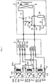
- FIG. 1 A refrigeration cycle diagram of a multi-room air conditioner in an exemplary embodiment of the invention is shown in Fig. 1.
- Fig. 1 through a branch unit 3, a plurality of (for example, three) indoor units 4a, 4b, 4c are connected to one outdoor unit 2, and further connected to the branch unit 3.
- Fig. 2. A refrigeration cycle diagram of a multi-room air conditioner in other exemplary embodiment of the invention is shown in Fig. 2.
- Fig. 2 a plurality of (for example, three) indoor units 4a, 4b, 4c are connected to one outdoor unit 2.
- the outdoor unit 2 comprises an inverter-driven variable capacity (frequency) compressor 6 (hereinafter called compressor), an outdoor heat exchanger 8, a refrigerant liquid side main pipe 14, a refrigerant gas side main pipe 18, a motor-driven expansion valve 7, a four-way valve 10 for cooling-heating changeover, a bypass duct 16, and a pressure reducing device 17.
- the motor-driven expansion valve 7 is installed in the refrigerant liquid side main pipe 14.
- the bypass duct 16 is bypass means of refrigerant from the refrigerant liquid side main pipe 14 to a suction pipe 15.
- the pressure reducing device 17 is installed in the bypass duct 16.
- the indoor units 4a, 4b, 4c have indoor heat exchangers 12a, 12b, 12c, respectively.
- the branch unit 3 includes liquid side branch pipes 16a, 16b, 16c branched off from the refrigerant liquid side main pipe 14, and gas side branch pipes 20a, 20b, 20c branched off from the refrigerant gas side main pipe 18.
- the outdoor unit 2 and indoor units 4a, 4b, 4c are connected by means of these liquid side branch pipes 16a, 16b, 16c and gas side branch pipes 20a, 20b, 20c.
- Motor-driven refrigerant distribution expansion valves 22a, 22b, 22c of which valve opening degree is pulse-controllable by a stepping motor or the like are installed in the liquid side branch pipes 16a, 16b, 16c.
- the indoor units 4a, 4b, 4c are provided with room temperature sensors 36a, 36b, 36c for detecting the room temperature, room humidity sensors 37a, 37b, 37c for detecting the room humidity, piping temperature sensors 39a, 39b, 39c for detecting the piping temperature of the heat exchangers, and operation setting circuits 38a, 38b, 38c.
- the operation setting circuits 38a, 38b, 38c are set by the inhabitants in the desired operation mode (cooling or heating), room temperature, and run or stop mode.
- the room temperature sensors 36a, 36b, 36c are one kind of room temperature detecting means.
- the room humidity sensors 37a, 37b, 37c are one kind of room humidity detecting means.
- the piping temperature sensors 39a, 39b, 39c are one kind of piping temperature detecting means.
- the outdoor unit 2 is provided with an ambient temperature sensor 40 for detecting the ambient temperature, a suction temperature sensor 42 for detecting the suction temperature of the compressor, and a saturation temperature sensor 41 for detecting the saturation temperature of suction pressure in the bypass duct 16 between the refrigerant liquid side main pipe and suction pipe.
- the liquid side branch pipes 16a, 16b, 16c branched off from the refrigerant liquid side main pipe 14, and gas side branch pipes 20a, 20b, 20c branched off from the refrigerant gas side main pipe 18 are installed in the outdoor unit 2.
- the motor-driven refrigerant distribution expansion valves 22a, 22b, 22c of which valve opening degree is pulse-controllable by a stepping motor or the like are installed respectively in the liquid side branch pipes 16a, 16b, 16c.
- the refrigerant discharged from the compressor 6 flows into the outdoor heat exchanger 8 through the four-way valve 10.
- This refrigerant exchanges heat with fresh air in the outdoor heat exchanger 8 as the outdoor blower 9 is driven, and is condensed and liquefied. Consequently, the refrigerant passes through the motor-driven expansion valve 7, and is reduced in pressure in a first stage.
- the refrigerant reduced in pressure passes through the refrigerant liquid side main pipe 14, and the refrigerant is distributed in the liquid side branch pipes 16a, 16b, 16c.
- the flow rate of the refrigerant distributed into plural indoor units is controlled.
- the refrigerant is evaporated in the indoor units 4a, 4b, 4c.
- the evaporated refrigerants converge at the refrigerant gas side main pipe 18 from the gas side branches.
- the converted refrigerant passes through the four-way valve 10, and is sucked again into the compressor 8.
- the refrigerant distribution expansion valves 22a, 22b , 22c are pulse-controlled by a stepping motor or the like so that the opening degree may be suited to the load in the room. Accordingly, the refrigerant is controlled at the flow rate depending on the room load.
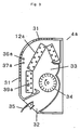
- FIG. 3 A structure of an indoor unit of a multi-room air conditioner in a different exemplary embodiment of the invention is shown in Fig. 3.
- plural suction ports 31 are formed in the upper part and front part of the main body of the indoor unit 4a.
- An air diffuser 32 is formed in the lower part of the main body.
- An indoor heat exchanger 12a and an indoor blower 34 are provided in an air passage 33 communicating between the suction ports 31 and air diffuser 32.
- a wind direction changing blade 35 is oscillatably provided in the air diffuser 32.
- a piping temperature sensor 39a is fitted in contact with the refrigerant piping of the indoor heat exchanger 12a disposed underneath.
- a room temperature sensor 36a and a room humidity sensor 37a are disposed in the main body.
- FIG. 4 A block diagram showing control and flow of compressor frequency and motor-driven expansion valve is shown in Fig. 4.
- signals of differential temperature, room load level, and target piping temperature are transmitted from plural indoor units, and the compressor frequency and motor-driven expansion valve are controlled.
- the output of the room temperature sensor 36a is sent out from a room temperature detecting circuit 48 to a differential temperature calculating circuit 50 as temperature signal.
- the signal from an operating setting circuit 38a is received in a signal receiving circuit 51.
- the temperature setting set in the operation setting circuit 38a is stored in a room temperature setting memory circuit 52.
- This temperature setting is sent out to the differential temperature calculating circuit 50.
- This differential temperature ⁇ T is the differential temperature signal.
- the room temperature is Tr, and the set temperature is Ts.
- the differential temperature calculating circuit 50 is one kind of differential temperature calculating means.
- the room temperature setting memory circuit 52 is one kind of room temperature setting memory means.
- the operation setting circuit 38a can set, aside from the temperature, also run/stop signal, operation mode such as cooling, dehumidifying and heating, air flow rate, automatic air flow rate, wind direction and automatic wind direction.
- the output of the room humidity sensor 37a is sent out from the room humidity detecting circuit 49 to the target piping temperature setting circuit 55 as humidity signal.
- the output of the room temperature sensor 36a is sent out from the room temperature detecting circuit 48 to the target piping temperature setting circuit 55 as temperature signal.
- the target piping temperature table 47 From the target piping temperature table 47, the target piping temperature controlled by the heat exchanger 12a of the indoor unit 4a is set.
- the piping temperature of the heat exchanger 12a is transmitted by the piping temperature sensor 39a and piping temperature detecting circuit 53 as piping temperature signal.
- the target piping temperature setting circuit 55 is one kind of target piping temperature setting means.
- the run/stop memory circuit 54 the signal set in the operation setting circuit 38a is received in the signal receiving circuit 51, and the run (ON) or stop (OFF) of the indoor unit 4a is stored.
- the run/stop memory circuit 54 is one kind of run/stop memory means.
- the operation mode memory circuit 59 the signal set in the operation setting circuit 38a is received in the signal receiving circuit 51, and the operation mode of cooling, dehumidifying or heating of the indoor unit 4a is stored.
- the rated capacity memory circuit 56 the rated capacity of the indoor unit 4a is stored.
- the model type memory circuit 57 the model type of the indoor unit 4a such as wall-mount type or ceiling built-in type is stored.
- the rated capacity signal, differential temperature signal, target piping temperature signal, operation mode signal, run/stop signal, model type signal, room temperature signal, room humidity signal, and piping temperature signal are sent out from a signal transmitting circuit 58 to a signal receiving circuit 80 in the branch unit 3, and these signals are sent out to a signal receiving circuit 60 of the outdoor unit 2 from a signal transmitting circuit 81.
- the signals received in the signal receiving circuit 60 are sent out to the compressor frequency operating circuit 62 and an expansion valve opening degree operating circuit 64.
- the rated capacity memory circuit 56 is one kind of rated capacity memory means.
- the model type memory circuit 57 is one kind of model type memory means.
- the compressor frequency operating circuit 62 is one kind of compressor frequency operating means.
- the expansion valve opening degree operating circuit 64 is one kind of expansion valve opening degree operating means.
- the signals transmitted from the plural indoor units 4a, 4b, 4c are received in the signal receiving circuit 80, and the highest temperature of the individual target piping temperatures is set in a control piping temperature operating circuit 84.
- the control piping temperature operating circuit 84 is one kind of control piping temperature operating means.
- the temperature data is transmitted from the signal transmitting circuit 81 of the branch unit 3 to the signal receiving circuit 60 of the indoor unit.
- the refrigerant distribution expansion valve opening degree operating circuit 82 calculates the refrigerant distribution ratio. On the basis of this refrigerant distribution ratio, the opening degree of the refrigerant distribution expansion valves 22a, 22b, 22c is set.
- the compressor frequency operating circuit 62 sets the load coefficient from the load coefficient table 66 on the basis of the rated capacity signal, differential temperature signal, operation mode signal and run/stop signal received from the indoor units 4a, 4b, 4c, and calculated as specified. As a result, the operation frequency is calculated.
- the expansion valve opening degree operating circuit 64 operates as specified from the load coefficient table 66 and valve initial opening degree table 70, similarly on the basis of the rated capacity signal, differential temperature signal, operation mode signal and run/stop signal received from the indoor units 4a, 4b, 4c. As a result, the opening degree of the motor-driven expansion valve 7 is determined.
- the control piping temperature transmitted from the branch unit 3 is set and stored in the control piping temperature setting circuit 61.
- the signals of the piping temperature and control piping temperature of the indoor unit transmitting the target piping temperature as the object of control are sent out to the compressor frequency operating circuit 62 or expansion valve opening degree operating circuit 64, and are compared and operated, and the compressor frequency or motor-driven expansion valve opening degree is controlled.
- the operation results determined in the compressor frequency operating circuit 62 and expansion valve opening degree operating circuit 64 are sent out to a compressor driving circuit (not shown) and an expansion valve driving circuit (not shown) as frequency signal and expansion valve opening degree signal, and the frequency of the compressor 6 and the opening degree of the motor-driven expansion valve 7 are controlled.
- the output of the ambient temperature sensor 40 is detected by the ambient temperature detecting circuit 63, and when the ambient temperature is changed, the expansion valve opening degree operating circuit 64 controls the expansion valve.
- the outputs of the saturation temperature sensor 41 and suction temperature sensor 42 are detected by the saturation temperature detecting circuit 67 and suction temperature detecting circuit 65.
- the detected results are compared and operated in an overheating degree operating circuit 68, and the expansion valve opening degree operating circuit 64 controls the expansion valve.
- the frequency number of the compressor 6 and the opening degree of the motor-driven expansion valve 7 are calculated, and the frequency of the compressor 6 and the opening degree of the motor-driven expansion valve 7 are controlled.
- the -heating operation is not the main object of the invention, and its explanation is omitted.
- Fig. 5 is a block diagram of a multi-room air conditioner having a structure of receiving signals from plural indoor units directly by an outdoor unit.
- the refrigerant distribution expansion valves 22a, 22b, 22c of the branch unit 3 are controlled by the outdoor unit 2.
- the control operation of the branch unit 3 is same as mentioned above, and its explanation is omitted.
- Fig. 6 is a temperature zone division diagram of differential temperature ⁇ T of room temperature Tr and set temperature Ts.
- the output of the room temperature sensor 36a is sent out from the room temperature detecting circuit 48 to the differential temperature operating means 22 as temperature signal.
- the set temperature set in the operation setting circuit 18a and the operation mode are stored and judged, and sent out to the differential temperature operating means 22.
- This load number Ln value is the differential temperature signal.
- Ln is 6.
- the load constant is read out from the load constant table 66 shown in Table 1, and by multiplying the sum of the load constants by a specific constant, the frequency of the compressor 6 is determined.
- Fig. 7 is the relation diagram of the sum of the load constants of the operating indoor units and the compressor frequency.
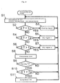
- Fig. 8 and Fig. 9 show the control method of cooling, dry 1 and dry 2 regions in dehumidifying mode.
- step S1 the differential temperature ⁇ T of the room temperature (Tr) detected by the room temperature sensor 36a and the set temperature (Ts) set by the user is calculated, and the compressor frequency is determined on the basis of this differential temperature ⁇ T as mentioned above.
- step S2 ⁇ T and t1 (for example, +0.5°C) are compared, and when ⁇ T is judged to be larger than t1, cooling operation is started at step S3. If ⁇ T is judged to be smaller than t1, the process goes to step S4.
- step S4 comparing ⁇ T and t2 (for example, -0.5°C), if ⁇ T is judged to be larger than t2, operation in dry region 1 is executed at step S5. When ⁇ T is judged to be smaller than t2, the process goes to step S6.
- ⁇ T and t2 for example, -0.5°C
- step S6 comparing ⁇ T and t3 (for example, -2.5°C), if ⁇ T is judged to be larger than t3, operation in dry region 2 is executed at step S7.
- ⁇ T is judged to be smaller than t3, the operation of the compressor 6 is stopped at step S8.
- step S9 after stopping the compressor 8, it is judged if a specified time (for example, about 3 minutes) has passed or not.
- a specified time for example, about 3 minutes
- ⁇ T is compared with t3.
- t3 When ⁇ T is larger than t3, the compressor 6 is started again at step S11.
- the room temperature is sampled in every specified time (for example, about 1 second), and by calculating ⁇ T on every occasion, the running condition is determined.
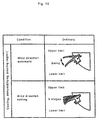
- the wind direction changing blade 35 swings between the upper limit position and lower limit position except when the indoor fan 34 is stopped.
- the user desires to set the wind direction, it can be set in five steps by the remote controller.
- the compressor frequency decreases extremely (the frequency number is, for example, 1).
- the indoor fan 22 is at the air flow rate in a range of a light breeze sLo.
- the frequency number of the compressor is set, for example, at 3.
- the air flow from the indoor fan 34 is set at medium air flow or light breeze sLo smaller than Lo.
- the frequency number of the compressor is set, for example, at 2. Further, as described later, the operation is set at either light breeze dry operation or windless stream dry operation depending on the operating condition.
- the air flow rate in light breeze dry operation is on/off operation of light breeze.
- wind direction automatic the wind direction changing blade 36 is set at an angle further lower than the lower limit position of the dry region 1.
- the cold air does not hit directly the inhabitants.
- wind direction setting it can be set at five steps from upper limit position to downward position by the remote controller.
- a cycle of running for about 15 seconds and stopping for about 10 seconds is repeated.
- the air flow rate is set at light breeze.
- the wind direction changing blade 36 is set at a position closing the air diffuser 32 (reset position) or near the closing position.
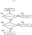
- This windless dry operation shifts to dry region 2 at step S7 when it is judged Yes at step S6, and starts when any one of the conditions in Table 3 continues (for example, for more than 5 minutes).
- condition is not established, for example, after 10 minutes, it is judged again whether the condition is established or not.
- step S21 it is judged if the piping temperature detected by the piping temperature sensor 39a is smaller than the target piping temperature (A)-3 or not. If smaller, at step S22, windless dry operation is immediately stopped. If larger, the process goes to step S23. At step S23, it is judged if the piping temperature is smaller than the target piping temperature (A)-2 or not. If smaller, at step S24, the windless dry operation continues for 30 minutes, and ends. If larger, going to step S25, the windless dry operation continues for 60 minutes, and ends.
- a specific time for example, about 5 minutes
- the target piping temperature (A) is determined according to Table 4, on the basis of the room temperature detected by the room temperature sensor 36a and the relative humidity detected by the humidity sensor 37a.
- the target piping temperature is changed.
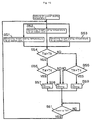
- the target piping temperature Ta of the indoor unit 1 is received.
- the target piping temperature Tb of the indoor unit 2 is received.
- the target piping temperature Tc of the indoor unit 3 is received.
- Ta and Tb are compared.
- Ta and Tc are compared.
- the control piping temperature is set at Ta, and is transmitted to the outdoor unit.
- Tc is higher than Ta at step S55, the control piping temperature is set at Tc.
- Ta and Tb are compared.
- Tb and Tc are compared at step S56, and when Tb is higher than Tc, the control piping temperature is set at Tb.
- Tc is higher than Tb at step S56, the control piping temperature is set at Tc, and is transmitted to the outdoor unit.
- step S61 to update the control piping temperature, after a specific time T0, a target piping temperature is received from the indoor unit, and the control piping temperature is set again.
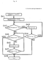
- step S42 the piping temperature detected by the piping temperature sensor of the indoor unit selected for the control piping temperature is judged if larger than A+1 or not. If the piping temperature is larger than A+1, at step S43, the frequency of the compressor 6 is raised by 1 Hz, and at step S44, it is checked if the increment of frequency is smaller than 5 Hz or not. If the increment of frequency is smaller than 5 Hz, in a specific time (for example, about 3 minutes), the process returns to step S42. If the increment of frequency is larger than 5 Hz, going to step S48, the compressor 6 is locked at the present frequency.
- step S42 if the piping temperature is smaller than A+1, at step S45, it is checked whether the piping temperature is larger than A-1 or not. If the value is smaller, at step S46, the frequency of the compressor 6 is decreased by 1 Hz, and the process goes to step S47. At step S47, it is checked if the decrement of frequency is smaller than 5 Hz or not. If the value is smaller, after a specific time (for example, about 3 minutes), the process returns to step S45. On the other hand, if the value is larger, at step S48, the compressor 6 is locked at the present frequency. Incidentally, at step S45, if the piping temperature is judged to be larger than A+1, too, the process goes to step S48, and the compressor 6 is locked at the present frequency.
- This frequency control of the compressor is the control to be done after the compressor frequency has been determined by the load constant from the indoor unit.
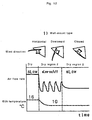
- Fig. 17 is an example of control time chart of the indoor unit 1 of a multi-room air conditioner in an embodiment of the invention.
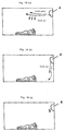
- Fig. 18 (a), (b), (c) show flow of cold air by the indoor unit wind direction control in the multi-room air conditioner in the embodiment of the invention.
- Fig. 18 (a) shows the running state in dry region 1 when setting in "wind direction automatic" in dehumidifying operation
- Fig. 18 (b) shows the on/off state of the indoor fan in dry region 2
- Fig. 18 (c) shows the windless dry operation state (c) in dry region 2.
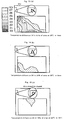
- Fig. 19 (a), (b), (c) show room temperature distribution by the indoor unit control in the mufti-room air conditioner in the embodiment of the invention, in the vertical direction to the indoor unit diffuser direction.
- Fig. 19 (a) shows the running state in dry region 1 in dehumidifying operation
- Fig. 19 (b) shows the on/off state of the indoor fan in dry region 2
- Fig. 19 (c) shows the windless dry operation state (c) in dry region 2.
- the dehumidifying amount is large, and the humidity drops.
- the inhabitants are not directly exposed to the cold wind, but the cold air falls down from the upper part of the room, and the entire room is enveloped in a cold air.
- the inhabitants feel coldness by the body.
- on/off operation in dry region 2 the inhabitants feel only a slight cold air from beneath, and hardly feel cold wind.
- the dehumidifying operation is powerful because the piping temperature of the indoor unit is controlled, and dew is not condensed around the diffuser of the indoor unit, and a safe dehumidifying operation is assured.
- windless dry operation in dry region 2 wind direction closed
- the inhabitants do not feel cold air from beneath, and the room is dehumidified in windless state, so that the inhabitants feel very comfortable.
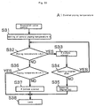
- control of opening degree of motor-driven expansion valve 7 is explained by referring to the flowchart in Fig. 20.
- step S31 in a specific time after the control piping temperature A has been set, at step S32, the piping temperature detected by the piping temperature sensor 24 of the indoor unit selected for the control piping temperature is judged if larger than A+1 or not. If the piping temperature is larger than A+1, at step S33, the motor-driven expansion valve 7 is closed, for example, by 4 pulses, and the valve opening degree is judged at step S34. At this time, if the valve opening degree is larger than the minimum setting pulses (for example, 60 pulses), the process returns to step S32. If this value is smaller than the minimum setting pulses, it is set to the minimum setting pulses at step S35.
- the minimum setting pulses for example, 60 pulses
- step S32 if the piping temperature is smaller than A+1, at step S36, it is checked whether the piping temperature is larger than A-1 or not. If the value is smaller, at step S37, the motor-driven expansion valve 7 is opened, for example, by 8 pulses. If the value is larger, at step S38, the motor-driven expansion valve 7 is locked at the present opening degree.
- This control of the motor-driven expansion valve is the control to be done after the opening degree of the expansion valve has been determined by the operation mode and load constant from the indoor unit.
- Table 5 shows the relation of the speed control of outdoor fan in synchronism with the frequency of the compressor.
- dehumidify by controlling the piping temperature of the indoor unit.
- it is designed to dehumidify while preventing drop of room temperature by minimizing the sensible heat capacity of cooling.
- the outdoor frequency is set at a low frequency, and by reducing the outdoor fan speed in synchronism, so that the sensible heat capacity is kept small.
- the target piping temperature is corrected depending on the model type of the indoor unit, whether wall-mount type or ceiling built-in type.
- correction of target piping temperature is, in the indoor unit, branch unit or outdoor unit, same as correction of target piping temperature in each indoor unit. Hence its explanation is omitted.
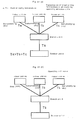
- Fig. 21 (a) plural indoor units are in dehumidifying operation, and the target piping temperatures Ta, Tb, Tc are transmitted to the branch unit 3, and the highest control piping temperature Ta is selected in the branch unit 3, and it is transmitted to the outdoor unit, and the compressor or expansion valve is controlled.
- Fig. 21 (b) shows the stopped state of the indoor unit 4a by receiving a stop signal in the running state in Fig. 21 (a). At this time, the indoor unit 4b transmitting the highest target piping temperature next to the indoor unit 4a among the running indoor units is selected for the control piping temperature.
- control piping temperature is selected from the target piping temperature, and the control continues without interruption. As a result, stable dehumidifying control is realized.
- Fig. 22 (a) plural indoor units are in dehumidifying operation, and the target piping temperatures Ta, Tb, Tc are transmitted to the branch unit 3, and the highest control piping temperature Ta is selected in the branch unit 3, and it is transmitted to the outdoor unit, and the compressor or expansion valve is controlled.
- Fig. 22 (b) shows the cooling operation state of the indoor unit 4a in the running state in Fig. 22 (a).
- selection of cooling operation among plural indoor units is recognized by the branch unit or outdoor unit.
- control of compressor and expansion valve of the outdoor unit from the target piping temperature of the indoor unit is not conducted.
- the method of control of compressor or expansion valve of the outdoor unit by the target piping temperature from the indoor unit if operating in one room, in the case of operation of heat exchange with room temperature, extremely, the piping temperature rises, and the dehumidifying amount decreases in dehumidifying operation in other rooms, or the refrigerant circulation amount in cooling operation increases, and the refrigeration distribution is broken, and the performance is lowered and refrigerant noise occurs.
- Fig. 23 (a) plural indoor units are in dehumidifying operation, and the target piping temperatures Ta, Tb, Tc are transmitted to the branch unit 3, and the highest control piping temperature Ta is selected in the branch unit 3, and it is transmitted to the outdoor unit, and the compressor or expansion valve is controlled.
- Fig. 23 (b) shows the cooling operation or getting into the cooling region by dehumidifying operation of the indoor unit 4c in the running state in Fig. 23 (a).
- the branch unit or outdoor unit recognizes the cooling operation among plural indoor units or selection of cooling operation by getting into the cooling region during dehumidifying operation.
- the control piping temperature is set, and is operated, and the compressor and expansion valve of the outdoor unit are controlled.
- This operation of the control piping temperature is processed so as to lower the temperature by a specific value. As a result, in the state of cooling operation or getting into cooling region during dehumidifying operation to start cooling operation, the control piping temperature is prevented from elevating by cooling operation.
- Fig. 24 (a) plural indoor units are in dehumidifying operation, and the target piping temperatures Ta, Tb, Tc are transmitted to the branch unit 3, and the highest control piping temperature Ta is selected in the branch unit 3, and it is transmitted to the outdoor unit, and the compressor or expansion valve is controlled.
- Fig. 24 (b) shows the cooling operation or getting into the cooling region by dehumidifying operation of the indoor unit 4c in the running state in Fig. 24 (a).
- the branch unit or outdoor unit recognizes the cooling operation among plural indoor units or selection of cooling operation by getting into the cooling region during dehumidifying operation.
- the control piping temperature is set, and is operated, and the compressor and expansion valve of the outdoor unit are controlled.
- This operation of the control piping temperature is processed so as to lower the temperature by a specific value. As a result, in the state of cooling operation or getting into cooling region during dehumidifying operation to start cooling operation, the control piping temperature is prevented from elevating by cooling operation.
- overheating degree control of the compressor by the expansion valve control is explained by referring to Table 6.
- the compressor frequency is controlled to be lowered, the overheating degree of the compressor increases, and the cooling capacity in the indoor unit in the refrigeration cycle is decreased.
- the compressor frequency becomes relatively low, and the dehumidifying operation is done in lowered room temperature state, and the temperature of the indoor unit reaches the set temperature, only the humidity can be removed without lowering the temperature.
- control of the indoor unit stopped by judgment of differential temperature in other room during control operation at the control piping temperature is explained by referring to Fig. 25 (a), Fig. 25 (b), and Fig. 26.
- Fig. 25 (a) plural indoor units are in dehumidifying operation, and the target piping temperatures Ta, Tb, Tc are transmitted to the branch unit 3, and the highest control piping temperature Ta is selected in the branch unit 3, and it is transmitted to the outdoor unit, and the compressor or expansion valve is controlled.
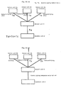
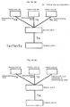
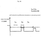
- Fig. 25 (b) during dehumidifying operation of the indoor unit 4c in the running state in Fig. 25 (a), when stopping of operation is judged by zero load factor (Ln0) from the differential temperature of room temperature and set temperature, the indoor fan is stopped for t4 time from the stopping time of operation, and then operating for t5 time, and then the indoor fan is stopped for about t4 time.
- the indoor fan is controlled in this manner.
- Plural indoor units are in dehumidifying operation, and the target piping temperatures Ta, Tb, Tc are transmitted to the branch unit 3, and the highest control piping temperature Ta is selected in the branch unit 3, and it is transmitted to the outdoor unit, and the compressor or expansion valve is controlled.
- the indoor unit of one room is stopped in this state and the indoor fan is operated immediately after, water drops formed on the indoor heat exchanger are prevented from being evaporated again to be supplied into the room.
- the indoor fan when stopping the indoor fan for a longer time, in order to prevent dew condensation water in the wind tunnel of the indoor unit, by operating for a while, the temperature of the indoor unit is sampled while suppressing re-evaporation. As a result, dew condensation in the wind tunnel can be prevented.
- the multi-room air conditioner of the embodiment has a constitution in which in order to dehumidify powerfully by a plurality of indoor units, the target piping temperature is set on the basis of the room temperature and the room humidity, and the highest temperature is selected, and the compressor frequency and expansion valve are controlled.
- the multi-room air conditioner connecting a plurality of indoor units has a simple structure, and assures safe and enough dehumidifying amount without condensing dew around the diffuser.
- the multi-room air conditioner of exemplary embodiment 2 has a constitution in which the piping temperature of the indoor unit is controlled by varying the opening degree of the expansion valve.
- the lower input and finer adjustment can be controlled, and the energy-saving property and control stability against dehumidifying load fluctuations are enhanced.
- the multi-room air conditioner of exemplary embodiment 3 has a constitution in which the outdoor fan control is decreased in synchronism when the frequency instruction of the compressor from the indoor side becomes a low frequency instruction.
- the refrigerant circulation amount and heat release amount are balanced, and abnormal low pressure operation is prevented, and oil circulation of the compressor is enabled. As a result, the reliability of the compressor is assured, and low input operation is possible.
- the multi-room air conditioner of exemplary embodiment 4 has a constitution in which the target piping temperature can be varied depending on the model type of the indoor unit.
- the target piping temperature can be corrected so that the limit of dew condensation around the diffuser may be different in each model type of the indoor unit. As a result, depending on the model type, dew condensation around the diffuser is prevented, and safe operation is assured.
- the control of the compressor frequency and expansion valve opening degree can be continued if a signal of target piping temperature is issued from other room.
- the multi-room air conditioner of exemplary embodiment 6 has a constitution in which if other indoor unit is put in cooling operation while plural indoor units are in dehumidifying operation, control on the basis of the target control temperature is not executed. In this constitution, the control of compressor frequency and expansion valve on the basis of the target piping temperature is stopped. As a result, safe operation of the air conditioner is assured. That is, in the state of the control of compressor frequency or expansion valve by the target piping temperature in the plurality of indoor units, when the indoor unit selected for the control piping temperature is put in cooling operation, the piping temperature of the indoor unit rises, and the dehumidifying amount drops. Or when the piping temperature is lowered, dew may be condensed around the diffuser in the indoor unit in cooling operation. Such defects are eliminated by this constitution, and safe operation is assured.
- the constitution of the multi-room air conditioner of exemplary embodiment 7 in the state of the control of compressor frequency or expansion valve by the target piping temperature in the plurality of indoor units, if the indoor unit selected for the control piping temperature is put in cooling operation, when the load constant of the indoor unit in cooling operation is low, the refrigerant circulation amount is small and the temperature exchange of the heat exchanger is small. As a result, the piping temperature hardly rises. Hence, drop of dehumidifying amount in other indoor units and flow changing sound of refrigerant circulation amount do not occur. Hence, the control of compressor frequency and expansion valve on the basis of the target piping temperature continues, so that safe operation is realized.
- the constitution of the multi-room air conditioner of exemplary embodiment 8 in the state of the control of compressor frequency or expansion valve by the target piping temperature in the plurality of indoor units, if the indoor unit selected for the control piping temperature is put in cooling operation, when fan speed of the indoor unit in cooling operation is the lowest speed, the temperature exchange of the heat exchanger is small, and the piping temperature hardly rises. Hence, drop of dehumidifying amount in other indoor units and flow changing sound of refrigerant circulation amount do not occur. Hence, the control of compressor frequency and expansion valve on the basis of the target piping temperature continues, so that safe operation is realized.
- the multi-room air conditioner of exemplary embodiment 9 in the state of control of compressor frequency by the target piping temperature in the plurality of indoor units, by throttling the opening degree of the expansion valve controlling the value of the overheating degree of the compressor depending on drop or change of the ambient temperature, it is controlled to raise the overheating degree, and the indoor cooling capacity is lowered by drop of the ambient temperature. As a result, drop of room temperature is prevented, and dehumidifying operation can be continued.
- the multi-room air conditioner of exemplary embodiment 10 in the state of control of compressor frequency, by the target piping temperature in the plurality of indoor units, by throttling the opening degree of the expansion valve controlling the value of the overheating degree of the compressor depending on drop or change of the compressor frequency, it is controlled to raise the overheating degree, and the refrigerant circulation amount is lowered by drop of the compressor frequency, so that the indoor cooling capacity is lowered. As a result, drop of room temperature is prevented, and dehumidifying operation can be continued.
- the multi-room air conditioner of exemplary embodiment 11 in the state of the control of compressor frequency or expansion valve by the target piping temperature in the plurality of indoor units, if the indoor unit selected for the control piping temperature is stopped due to differential temperature operation of the room temperature and set temperature, the fan of the stopped indoor unit is stopped, and then intermittent operation is started, and therefore re-evaporation upon start of operation of the fan of the stopped indoor unit is prevented, and room temperature can be sampled in the subsequent intermittent operation, and dew condensation in the wind tunnel can be prevented.
- the multi-room air conditioner having the following features is obtained.
- the dehumidifying performance is enhanced. Air stream feel and cold wind feel for the inhabitants are suppressed. Energy-saving performance and silent operation are excellent. Dew condensation is prevented around the diffuser of the indoor unit. Individual temperature controllability of each indoor unit is excellent. The cost performance is excellent and it is inexpensive. A windless dehumidifying operation suppressed in air stream feel and cold wind feel is realized.
Landscapes
- Engineering & Computer Science (AREA)
- Mechanical Engineering (AREA)
- General Engineering & Computer Science (AREA)
- Chemical & Material Sciences (AREA)
- Combustion & Propulsion (AREA)
- Physics & Mathematics (AREA)
- Thermal Sciences (AREA)
- Signal Processing (AREA)
- Fluid Mechanics (AREA)
- Fuzzy Systems (AREA)
- Mathematical Physics (AREA)
- Human Computer Interaction (AREA)
- Air Conditioning Control Device (AREA)
- Compression-Type Refrigeration Machines With Reversible Cycles (AREA)
Applications Claiming Priority (2)
| Application Number | Priority Date | Filing Date | Title |
|---|---|---|---|
| JP28558699 | 1999-10-06 | ||
| JP11285586A JP3137114B1 (ja) | 1999-10-06 | 1999-10-06 | 多室形空気調和装置 |
Publications (3)
| Publication Number | Publication Date |
|---|---|
| EP1091178A2 true EP1091178A2 (de) | 2001-04-11 |
| EP1091178A3 EP1091178A3 (de) | 2002-09-25 |
| EP1091178B1 EP1091178B1 (de) | 2006-11-08 |
Family
ID=17693479
Family Applications (1)
| Application Number | Title | Priority Date | Filing Date |
|---|---|---|---|
| EP00116247A Expired - Lifetime EP1091178B1 (de) | 1999-10-06 | 2000-08-08 | Klimaanlage für mehrere Räume und Steuerverfahren hierfür |
Country Status (5)
| Country | Link |
|---|---|
| EP (1) | EP1091178B1 (de) |
| JP (1) | JP3137114B1 (de) |
| CN (1) | CN1179158C (de) |
| ES (1) | ES2275462T3 (de) |
| MY (1) | MY126793A (de) |
Cited By (22)
| Publication number | Priority date | Publication date | Assignee | Title |
|---|---|---|---|---|
| KR100487780B1 (ko) * | 2002-07-03 | 2005-05-06 | 엘지전자 주식회사 | 공기조화기의 운전제어방법 |
| DE102005050666A1 (de) * | 2005-03-31 | 2006-10-19 | Klaus Ferl | Temperaturregelung für Thermodecke direktverdampfend |
| EP1684030A3 (de) * | 2004-12-14 | 2006-11-29 | LG Electronics Inc. | Verfahren zum Betreiben einer Klimaanlage |
| EP1624257A3 (de) * | 2004-08-04 | 2009-11-25 | Samsung Electronics Co., Ltd. | Mehrzonenklimaanlage mit verbessertem Wirkungsgrad |
| EP2187141A3 (de) * | 2008-11-17 | 2010-08-11 | Mitsubishi Electric Corporation | Klimaanlage |
| EP1672297A3 (de) * | 2004-12-14 | 2010-10-06 | LG Electronics Inc. | Steuerverfahren für eine Innenraumeinheit einer Klimaanlage |
| WO2011132198A3 (en) * | 2010-04-20 | 2012-01-05 | Amrish Chopra | Heating, ventilation, air-conditioning system and method to operate such system |
| CN102865646A (zh) * | 2011-07-06 | 2013-01-09 | 三菱电机株式会社 | 空气调节器 |
| WO2013019537A3 (en) * | 2011-07-29 | 2013-10-10 | Carrier Corporation | Hvac systems |
| EP2551614A3 (de) * | 2011-07-26 | 2014-12-24 | Samsung Electronics Co., Ltd. | Klimaanlage und Steuerverfahren dafür |
| WO2015037360A1 (en) * | 2013-09-10 | 2015-03-19 | Mitsubishi Electric Corporation | Branch controller, system for temperature and humidity control, and method for controlling temperature and humidity |
| CN104823000A (zh) * | 2012-11-30 | 2015-08-05 | 三菱电机株式会社 | 设备器械运用装置、设备器械运用系统、设备器械运用方法以及程序 |
| EP2835602A4 (de) * | 2012-03-27 | 2016-05-25 | Mitsubishi Electric Corp | Klimaanlagenvorrichtung |
| EP3104090A4 (de) * | 2014-04-24 | 2017-04-12 | Mitsubishi Heavy Industries, Ltd. | Steuerungsvorrichtung einer mehrfachklimaanlage, mehrfachklimaanlagensystem damit sowie steuerungsverfahren und steuerungsprogramm für die mehrfachklimaanlage |
| EP3604948A4 (de) * | 2018-03-09 | 2020-07-15 | GD Midea Air-Conditioning Equipment Co., Ltd. | Klimaanlage, steuerungsverfahren dafür und computerlesbares speichermedium |
| US10780901B2 (en) | 2016-01-08 | 2020-09-22 | Mitsubishi Electric Corporation | Rail car air-conditioning device, and rail car air-conditioning device driving method |
| EP3770519A4 (de) * | 2018-03-21 | 2021-12-29 | Qingdao Hisense Hitachi Air-Conditioning Systems Co. Ltd. | Multi-split-system und verfahren zur gemeinsamen entfeuchtung dafür |
| CN113865059A (zh) * | 2021-09-22 | 2021-12-31 | 青岛海尔空调电子有限公司 | 多联机空调器制热运行控制方法 |
| CN115406064A (zh) * | 2021-05-26 | 2022-11-29 | 美的集团股份有限公司 | 多联机空调控制方法、装置、设备及存储介质 |
| CN115523626A (zh) * | 2021-06-24 | 2022-12-27 | 美的集团股份有限公司 | 无风感控制方法、装置、存储介质及空调器 |
| CN115751674A (zh) * | 2022-11-30 | 2023-03-07 | 青岛海尔空调器有限总公司 | 用于空调器的控制方法及控制装置、空调器、存储介质 |
| EP4563911A4 (de) * | 2022-07-28 | 2025-11-05 | Foshan Shunde Midea Electric Science And Tech Co Ltd | Multisplit-klimaanlage und verfahren zur steuerung davon, steuergerät und speichermedium |
Families Citing this family (31)
| Publication number | Priority date | Publication date | Assignee | Title |
|---|---|---|---|---|
| JP3719366B2 (ja) * | 2000-03-22 | 2005-11-24 | 三菱電機株式会社 | 空気調和機 |
| JP3754343B2 (ja) * | 2001-10-30 | 2006-03-08 | 三洋電機株式会社 | 空気調和装置 |
| JP3984054B2 (ja) * | 2002-01-11 | 2007-09-26 | 東芝キヤリア株式会社 | 空気調和機、空気調和機の制御方法 |
| KR100540808B1 (ko) * | 2003-10-17 | 2006-01-10 | 엘지전자 주식회사 | 히트펌프 시스템의 과열도 제어 방법 |
| JP4151625B2 (ja) * | 2004-07-21 | 2008-09-17 | 松下電器産業株式会社 | 空気調和機 |
| CN100432568C (zh) * | 2004-09-24 | 2008-11-12 | 乐金电子(天津)电器有限公司 | 中央空调的分配器 |
| KR100640858B1 (ko) | 2004-12-14 | 2006-11-02 | 엘지전자 주식회사 | 공기조화기 및 그 제어방법 |
| CN102353121B (zh) * | 2011-09-13 | 2013-08-28 | Tcl空调器(中山)有限公司 | 一种多联机冷媒流量的控制方法 |
| CN103017298A (zh) * | 2012-12-29 | 2013-04-03 | 南通宁普电器有限公司 | 一种防止凝露的变频空调的控制方法 |
| CN102997381B (zh) * | 2013-01-07 | 2014-12-24 | 四川长虹电器股份有限公司 | 一种空调控制系统 |
| JP5959473B2 (ja) * | 2013-05-09 | 2016-08-02 | 三菱電機株式会社 | 空気調和機 |
| CN104728998B (zh) * | 2013-12-23 | 2017-08-01 | 珠海格力电器股份有限公司 | 光伏供电空调机组的控制方法和装置 |
| JP6519263B2 (ja) * | 2015-03-26 | 2019-05-29 | 株式会社富士通ゼネラル | 空気調和機 |
| US9709311B2 (en) | 2015-04-27 | 2017-07-18 | Emerson Climate Technologies, Inc. | System and method of controlling a variable-capacity compressor |
| US9562710B2 (en) * | 2015-04-27 | 2017-02-07 | Emerson Climate Technologies, Inc. | Diagnostics for variable-capacity compressor control systems and methods |
| CN105115063A (zh) * | 2015-10-14 | 2015-12-02 | 珠海格力电器股份有限公司 | 空调系统 |
| US10408517B2 (en) | 2016-03-16 | 2019-09-10 | Emerson Climate Technologies, Inc. | System and method of controlling a variable-capacity compressor and a variable speed fan using a two-stage thermostat |
| US10760814B2 (en) | 2016-05-27 | 2020-09-01 | Emerson Climate Technologies, Inc. | Variable-capacity compressor controller with two-wire configuration |
| JP7034254B2 (ja) * | 2018-03-16 | 2022-03-11 | 三菱電機株式会社 | 空気調和機 |
| CN108679820B (zh) * | 2018-04-18 | 2021-05-25 | 青岛海尔空调器有限总公司 | 一种防凝露的空调控制方法及装置 |
| CN108613343A (zh) * | 2018-05-28 | 2018-10-02 | 广东美的暖通设备有限公司 | 一种空调器的控制方法及控制系统 |
| CN110631233B (zh) * | 2018-06-21 | 2022-06-28 | 重庆海尔空调器有限公司 | 一种空气调节系统、方法、装置及计算机可读存储介质 |
| TWI668542B (zh) * | 2018-09-26 | 2019-08-11 | 綠潔能科技股份有限公司 | 智慧型冷暖控制方法與控制器 |
| CN110285492B (zh) * | 2019-06-28 | 2021-07-27 | 广东美的暖通设备有限公司 | 空调系统、控制装置和控制系统 |
| CN111121228A (zh) * | 2019-12-18 | 2020-05-08 | 宁波奥克斯电气股份有限公司 | 一种开启防凝露模式的判断方法、判断装置和空调器 |
| JP2021156502A (ja) * | 2020-03-27 | 2021-10-07 | 株式会社富士通ゼネラル | 空気調和装置 |
| CN112283791B (zh) * | 2020-10-29 | 2023-08-11 | 青岛海信日立空调系统有限公司 | 一种空调器和流量阀的控制方法 |
| CN115704597B (zh) * | 2021-08-11 | 2025-06-27 | 美的集团武汉暖通设备有限公司 | 多联机空调及其控制方法、计算机可读存储介质 |
| CN115875827A (zh) * | 2021-09-28 | 2023-03-31 | 广州松下空调器有限公司 | 一种空调器的控制方法、装置及空调器 |
| JP2024034633A (ja) * | 2022-09-01 | 2024-03-13 | 日立ジョンソンコントロールズ空調株式会社 | 空気調和機 |
| CN115419992B (zh) * | 2022-09-14 | 2024-08-09 | 珠海格力电器股份有限公司 | 空调器控制方法、装置、电子设备及可读介质 |
Citations (1)
| Publication number | Priority date | Publication date | Assignee | Title |
|---|---|---|---|---|
| JPH07324841A (ja) | 1994-06-01 | 1995-12-12 | Matsushita Seiko Co Ltd | 多室型空気調和装置 |
Family Cites Families (5)
| Publication number | Priority date | Publication date | Assignee | Title |
|---|---|---|---|---|
| JPH08189690A (ja) * | 1995-01-13 | 1996-07-23 | Matsushita Electric Ind Co Ltd | 多室形空気調和システムの暖房除湿運転制御装置 |
| JPH09310927A (ja) * | 1996-05-22 | 1997-12-02 | Matsushita Seiko Co Ltd | 空気調和機の冷媒制御装置 |
| JPH11173628A (ja) * | 1997-12-15 | 1999-07-02 | Mitsubishi Heavy Ind Ltd | 空気調和装置 |
| JP3454697B2 (ja) * | 1997-12-22 | 2003-10-06 | 東芝キヤリア株式会社 | 空気調和機 |
| JP2912605B1 (ja) * | 1998-02-26 | 1999-06-28 | 松下電器産業株式会社 | 空気調和システムにおける冷媒循環チェック方法 |
-
1999
- 1999-10-06 JP JP11285586A patent/JP3137114B1/ja not_active Expired - Lifetime
-
2000
- 2000-08-08 ES ES00116247T patent/ES2275462T3/es not_active Expired - Lifetime
- 2000-08-08 EP EP00116247A patent/EP1091178B1/de not_active Expired - Lifetime
- 2000-08-09 MY MYPI20003633 patent/MY126793A/en unknown
- 2000-08-29 CN CNB001264834A patent/CN1179158C/zh not_active Expired - Fee Related
Patent Citations (1)
| Publication number | Priority date | Publication date | Assignee | Title |
|---|---|---|---|---|
| JPH07324841A (ja) | 1994-06-01 | 1995-12-12 | Matsushita Seiko Co Ltd | 多室型空気調和装置 |
Cited By (32)
| Publication number | Priority date | Publication date | Assignee | Title |
|---|---|---|---|---|
| KR100487780B1 (ko) * | 2002-07-03 | 2005-05-06 | 엘지전자 주식회사 | 공기조화기의 운전제어방법 |
| EP1624257A3 (de) * | 2004-08-04 | 2009-11-25 | Samsung Electronics Co., Ltd. | Mehrzonenklimaanlage mit verbessertem Wirkungsgrad |
| EP1684030A3 (de) * | 2004-12-14 | 2006-11-29 | LG Electronics Inc. | Verfahren zum Betreiben einer Klimaanlage |
| EP1672297A3 (de) * | 2004-12-14 | 2010-10-06 | LG Electronics Inc. | Steuerverfahren für eine Innenraumeinheit einer Klimaanlage |
| DE102005050666A1 (de) * | 2005-03-31 | 2006-10-19 | Klaus Ferl | Temperaturregelung für Thermodecke direktverdampfend |
| EP2187141A3 (de) * | 2008-11-17 | 2010-08-11 | Mitsubishi Electric Corporation | Klimaanlage |
| US8306667B2 (en) | 2008-11-17 | 2012-11-06 | Mitsubishi Electric Corporation | Air-conditioning apparatus |
| WO2011132198A3 (en) * | 2010-04-20 | 2012-01-05 | Amrish Chopra | Heating, ventilation, air-conditioning system and method to operate such system |
| CN102865646A (zh) * | 2011-07-06 | 2013-01-09 | 三菱电机株式会社 | 空气调节器 |
| CN102865646B (zh) * | 2011-07-06 | 2015-06-17 | 三菱电机株式会社 | 空气调节器 |
| EP2551614A3 (de) * | 2011-07-26 | 2014-12-24 | Samsung Electronics Co., Ltd. | Klimaanlage und Steuerverfahren dafür |
| WO2013019537A3 (en) * | 2011-07-29 | 2013-10-10 | Carrier Corporation | Hvac systems |
| US9885489B2 (en) | 2011-07-29 | 2018-02-06 | Carrier Corporation | HVAC systems |
| EP2835602A4 (de) * | 2012-03-27 | 2016-05-25 | Mitsubishi Electric Corp | Klimaanlagenvorrichtung |
| US9683768B2 (en) | 2012-03-27 | 2017-06-20 | Mitsubishi Electric Corporation | Air-conditioning apparatus |
| CN104823000A (zh) * | 2012-11-30 | 2015-08-05 | 三菱电机株式会社 | 设备器械运用装置、设备器械运用系统、设备器械运用方法以及程序 |
| US9715240B2 (en) | 2012-11-30 | 2017-07-25 | Mitsubishi Electric Corporation | Facility equipment operation device, facility equipment operation system, facility equipment operation method, and medium |
| EP2927613A4 (de) * | 2012-11-30 | 2016-12-28 | Mitsubishi Electric Corp | Anlagenausrüstungsbetriebsvorrichtung, anlagenausrüstungsbetriebssystem, anlagenausrüstungsbetriebsverfahren und programm |
| US9518765B2 (en) | 2013-09-10 | 2016-12-13 | Mitsubishi Electric Research Laboratories, Inc. | System and method for controlling temperature and humidity in multiple spaces using liquid desiccant |
| CN105531547A (zh) * | 2013-09-10 | 2016-04-27 | 三菱电机株式会社 | 分支控制器、温度和湿度控制系统及控制温度和湿度的方法 |
| WO2015037360A1 (en) * | 2013-09-10 | 2015-03-19 | Mitsubishi Electric Corporation | Branch controller, system for temperature and humidity control, and method for controlling temperature and humidity |
| CN105531547B (zh) * | 2013-09-10 | 2019-06-11 | 三菱电机株式会社 | 分支控制器、温度和湿度控制系统及控制温度和湿度的方法 |
| EP3104090A4 (de) * | 2014-04-24 | 2017-04-12 | Mitsubishi Heavy Industries, Ltd. | Steuerungsvorrichtung einer mehrfachklimaanlage, mehrfachklimaanlagensystem damit sowie steuerungsverfahren und steuerungsprogramm für die mehrfachklimaanlage |
| US10780901B2 (en) | 2016-01-08 | 2020-09-22 | Mitsubishi Electric Corporation | Rail car air-conditioning device, and rail car air-conditioning device driving method |
| EP3604948A4 (de) * | 2018-03-09 | 2020-07-15 | GD Midea Air-Conditioning Equipment Co., Ltd. | Klimaanlage, steuerungsverfahren dafür und computerlesbares speichermedium |
| EP3770519A4 (de) * | 2018-03-21 | 2021-12-29 | Qingdao Hisense Hitachi Air-Conditioning Systems Co. Ltd. | Multi-split-system und verfahren zur gemeinsamen entfeuchtung dafür |
| CN115406064A (zh) * | 2021-05-26 | 2022-11-29 | 美的集团股份有限公司 | 多联机空调控制方法、装置、设备及存储介质 |
| EP4310405A4 (de) * | 2021-05-26 | 2024-09-04 | Midea Group Co., Ltd. | Verfahren und vorrichtung zur steuerung einer multisplit-klimaanlage, vorrichtung und speichermedium |
| CN115523626A (zh) * | 2021-06-24 | 2022-12-27 | 美的集团股份有限公司 | 无风感控制方法、装置、存储介质及空调器 |
| CN113865059A (zh) * | 2021-09-22 | 2021-12-31 | 青岛海尔空调电子有限公司 | 多联机空调器制热运行控制方法 |
| EP4563911A4 (de) * | 2022-07-28 | 2025-11-05 | Foshan Shunde Midea Electric Science And Tech Co Ltd | Multisplit-klimaanlage und verfahren zur steuerung davon, steuergerät und speichermedium |
| CN115751674A (zh) * | 2022-11-30 | 2023-03-07 | 青岛海尔空调器有限总公司 | 用于空调器的控制方法及控制装置、空调器、存储介质 |
Also Published As
| Publication number | Publication date |
|---|---|
| EP1091178A3 (de) | 2002-09-25 |
| ES2275462T3 (es) | 2007-06-16 |
| JP2001108323A (ja) | 2001-04-20 |
| EP1091178B1 (de) | 2006-11-08 |
| CN1291702A (zh) | 2001-04-18 |
| CN1179158C (zh) | 2004-12-08 |
| MY126793A (en) | 2006-10-31 |
| JP3137114B1 (ja) | 2001-02-19 |
Similar Documents
| Publication | Publication Date | Title |
|---|---|---|
| EP1091178A2 (de) | Klimaanlage für mehrere Räume und Steuerverfahren hierfür | |
| JP2001248937A (ja) | ヒートポンプ給湯エアコン | |
| JP3529449B2 (ja) | 空気調和装置 | |
| JP2002107001A (ja) | 空気調和機 | |
| EP1010952B1 (de) | Verfahren zur Steuerung der Richtung des Luftstromes in einer Klimaanlage | |
| JP3643162B2 (ja) | 空気調和装置 | |
| JP2009014321A (ja) | 空気調和機 | |
| JP3936345B2 (ja) | 空気調和機 | |
| JP3729552B2 (ja) | 空気調和装置 | |
| JPH043865A (ja) | 冷凍サイクル装置 | |
| JP4483141B2 (ja) | 空気調和機 | |
| JPH1183128A (ja) | 異能力マルチエアコンシステム | |
| JPH09138012A (ja) | 空気調和機 | |
| JP2001208401A (ja) | 空気調和機 | |
| JP3149625B2 (ja) | 空気調和装置の運転制御装置 | |
| JPH02223757A (ja) | 空気調和機 | |
| JP3075022B2 (ja) | 空気調和機の制御装置 | |
| JPH08121902A (ja) | 空気調和装置 | |
| JP3378712B2 (ja) | 空気調和機 | |
| JP2536313B2 (ja) | 空気調和装置の運転制御装置 | |
| JP3380384B2 (ja) | 空気調和機の制御装置 | |
| JP2019143966A (ja) | 空気調和装置 | |
| JP4420393B2 (ja) | 冷凍空調装置 | |
| JP2911253B2 (ja) | 冷媒加熱式マルチ冷凍サイクル | |
| WO2019159621A1 (ja) | 空気調和装置 |
Legal Events
| Date | Code | Title | Description |
|---|---|---|---|
| PUAI | Public reference made under article 153(3) epc to a published international application that has entered the european phase |
Free format text: ORIGINAL CODE: 0009012 |
|
| AK | Designated contracting states |
Kind code of ref document: A2 Designated state(s): AT BE CH CY DE DK ES FI FR GB GR IE IT LI LU MC NL PT SE |
|
| AX | Request for extension of the european patent |
Free format text: AL;LT;LV;MK;RO;SI |
|
| PUAL | Search report despatched |
Free format text: ORIGINAL CODE: 0009013 |
|
| AK | Designated contracting states |
Kind code of ref document: A3 Designated state(s): AT BE CH CY DE DK ES FI FR GB GR IE IT LI LU MC NL PT SE |
|
| AX | Request for extension of the european patent |
Free format text: AL;LT;LV;MK;RO;SI |
|
| RIC1 | Information provided on ipc code assigned before grant |
Free format text: 7F 24F 11/00 A, 7F 24F 3/06 B |
|
| 17P | Request for examination filed |
Effective date: 20021218 |
|
| AKX | Designation fees paid |
Designated state(s): ES GR IT |
|
| REG | Reference to a national code |
Ref country code: DE Ref legal event code: 8566 |
|
| GRAP | Despatch of communication of intention to grant a patent |
Free format text: ORIGINAL CODE: EPIDOSNIGR1 |
|
| GRAS | Grant fee paid |
Free format text: ORIGINAL CODE: EPIDOSNIGR3 |
|
| RTI1 | Title (correction) |
Free format text: MULTIROOM AIR CONDITIONER AND CONTROL METHOD THEREFOR |
|
| GRAA | (expected) grant |
Free format text: ORIGINAL CODE: 0009210 |
|
| AK | Designated contracting states |
Kind code of ref document: B1 Designated state(s): ES GR IT |
|
| REG | Reference to a national code |
Ref country code: GR Ref legal event code: EP Ref document number: 20070400207 Country of ref document: GR |
|
| REG | Reference to a national code |
Ref country code: ES Ref legal event code: FG2A Ref document number: 2275462 Country of ref document: ES Kind code of ref document: T3 |
|
| PLBE | No opposition filed within time limit |
Free format text: ORIGINAL CODE: 0009261 |
|
| STAA | Information on the status of an ep patent application or granted ep patent |
Free format text: STATUS: NO OPPOSITION FILED WITHIN TIME LIMIT |
|
| 26N | No opposition filed |
Effective date: 20070809 |
|
| PG25 | Lapsed in a contracting state [announced via postgrant information from national office to epo] |
Ref country code: GR Free format text: LAPSE BECAUSE OF NON-PAYMENT OF DUE FEES Effective date: 20070209 |
|
| REG | Reference to a national code |
Ref country code: ES Ref legal event code: FD2A Effective date: 20070809 |
|
| PG25 | Lapsed in a contracting state [announced via postgrant information from national office to epo] |
Ref country code: ES Free format text: LAPSE BECAUSE OF NON-PAYMENT OF DUE FEES Effective date: 20070809 |
|
| PG25 | Lapsed in a contracting state [announced via postgrant information from national office to epo] |
Ref country code: IT Free format text: LAPSE BECAUSE OF NON-PAYMENT OF DUE FEES Effective date: 20070808 |