EP1091205B1 - Appareil de détection spectrophotométrique et néphélométrique - Google Patents
Appareil de détection spectrophotométrique et néphélométrique Download PDFInfo
- Publication number
- EP1091205B1 EP1091205B1 EP00119806A EP00119806A EP1091205B1 EP 1091205 B1 EP1091205 B1 EP 1091205B1 EP 00119806 A EP00119806 A EP 00119806A EP 00119806 A EP00119806 A EP 00119806A EP 1091205 B1 EP1091205 B1 EP 1091205B1
- Authority
- EP
- European Patent Office
- Prior art keywords
- light
- light sources
- diaphragm
- sensor
- sources
- Prior art date
- Legal status (The legal status is an assumption and is not a legal conclusion. Google has not performed a legal analysis and makes no representation as to the accuracy of the status listed.)
- Expired - Lifetime
Links
Images

Classifications
-
- G—PHYSICS
- G01—MEASURING; TESTING
- G01N—INVESTIGATING OR ANALYSING MATERIALS BY DETERMINING THEIR CHEMICAL OR PHYSICAL PROPERTIES
- G01N21/00—Investigating or analysing materials by the use of optical means, i.e. using sub-millimetre waves, infrared, visible or ultraviolet light
- G01N21/17—Systems in which incident light is modified in accordance with the properties of the material investigated
- G01N21/47—Scattering, i.e. diffuse reflection
- G01N21/49—Scattering, i.e. diffuse reflection within a body or fluid
- G01N21/51—Scattering, i.e. diffuse reflection within a body or fluid inside a container, e.g. in an ampoule
-
- G—PHYSICS
- G01—MEASURING; TESTING
- G01N—INVESTIGATING OR ANALYSING MATERIALS BY DETERMINING THEIR CHEMICAL OR PHYSICAL PROPERTIES
- G01N21/00—Investigating or analysing materials by the use of optical means, i.e. using sub-millimetre waves, infrared, visible or ultraviolet light
- G01N21/17—Systems in which incident light is modified in accordance with the properties of the material investigated
- G01N21/25—Colour; Spectral properties, i.e. comparison of effect of material on the light at two or more different wavelengths or wavelength bands
- G01N21/31—Investigating relative effect of material at wavelengths characteristic of specific elements or molecules, e.g. atomic absorption spectrometry
Definitions
- the present invention relates to a method and a device for substantially simultaneous performance of spectrophotometric and nephelometric analyzes, especially in in vitro diagnostics.
- an analyzer in US 4,325,910, includes a photometer that distributes light from a single light source to multiple light paths so as to perform multiple photometric measurements.
- WO 98/00701 describes a combination of a nephelometer with a turbidimeter consisting of two light sources. While one of them generates the scattered light as a laser, which is detected at 90 °, a diode (LED) emitting in the infrared spectral range serves to measure the turbidity in the axis of the incident light.
- the method described in the application serves, in particular, for improved control of the intensity of the laser used.
- the object of the present invention was therefore to find a device in which the substantially simultaneous spectrophotometric and nephelometric measurement in a sample within an assembly is possible.
- the time interval will have to be shorter than, for example, end point measurements, in which the time interval of the measurements is essentially determined by the mechanical size of the rotational / translational movement of the measuring cell in relation to the measuring location. For kinetic measurements, however, the time interval must be as short as possible.
- the present invention describes an apparatus in which a combination of methods for performing in vitro diagnostics analyzes based on the principle of scattered light measurement and spectrophotometry is possible.
- methods of photometry and scattered light measurement can be used substantially simultaneously by the measuring unit.
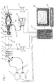
- One or more light sources 1, 2 are guided via a common beam guide along a beam axis 24 to the reaction site 11.
- sensors 17 and 25 scattered light or photometric signals can be detected.
- a pulse-shaped control both processes are decoupled in time so that there is no mutual interference or disturbances during operation.
- nephelometry is used predominantly for the analysis of agglutination tests and in particle-enhanced immunodiagnostics
- photometry serves to measure numerous other spectral changes based on clinical-chemical parameters.
- the combination achieves the goal of being able to perform a large number of different diagnostic tests of clinical chemistry, immunodiagnostics, plasma protein diagnostics or coagulation diagnostics on a single module.
- the present description relates to the field of use of automated measuring systems in analysis and in-vitro diagnostics.
- the described device makes the simultaneous performance of tests possible, which are measured by means of a scattered light measurement and / or by photometry in the UV-Vis spectral range.
- the unit can be integrated into systems in which the measurement of a plurality of samples and testing in cuvettes on a common rotor or carousel is performed, as is often the case for automatic analysis systems.
- a device has been developed by which it is possible to measure both the scattered light of a sample produced at angles outside the axis of the incident light and the light passing through angles of 0 °.
- Different narrowband or broadband light sources can be used to excite the material to be measured. These are guided on a common beam guidance to the reaction site. Due to the pulsed control of the light sources mutual interference or interference can be completely suppressed.
- Fig. 1 schematically shows an arrangement of light sources 1,2, Meßgutage 11 (cuvette) and detectors 17,22,25.
- solid angles around the axis of the incident light are utilized.
- the scattered light is detected at an angle of 90 °.
- a separation of the incident light to the scattered light can be achieved particularly easily.
- by choosing a larger solid angle range and taking advantage of angles or angular ranges about the forward direction of the incident light higher intensities of the scattered light can be achieved, whereby an arrangement can be technically easier and cheaper to build.
- the proportion of scattered light at angles around the forward direction is particularly high.
- the light sources 1, 2 used for the analysis have different spectral bandwidths according to the intended application. While a light source for the scattered light measurement has a narrowband emission in the red or infrared spectral range, preferably in the range between 650 and 950 nm, the light source for photometric measurements typically emits in a spectral range between 300 and 800 nm. In the present embodiment, both light sources are pulsed used.
- the light of both sources is guided, for example, via optical fibers or fiber bundles to a coupling unit 4 and coupled out via suitable optical components.
- a dichroic beam splitter 5 specially adapted for the two bandwidths makes it possible to guide both light sources on the common beam axis 24.
- the beam is collimated for the later measurement.
- a fraction of the incident light for reference measurement 22,23 be hidden.
- Meßgut 12 incident light beam leads to scattering or absorption depending on the type of Meßgut.
- both methods can be carried out independently of each other.
- the information necessary for triggering one of the light sources can be selected via a test definition necessary before the measurement and is thus known to the system during the execution of the measurement.
- the physical separation of the continuous in the axis and the scattered light 20 is effected by a arranged in the beam axis aperture 13.
- the aperture is advantageously designed so that it serves as a scattered light trap and on the other hand as a deflection unit for incident light in the axis.
- the aperture is constructed as a ring and pinhole. By choosing an inner and outer diameter of the most favorable for the analysis solid angle range can be selected.
- the portion which passes through the aperture as stray light is focused onto the input of a detector 17 by means of a lens or a lens system 14.
- the scattered light measurement is usually a discrete, narrow-band wavelength
- a broadband light source is used for the photometric measurement, so that the signal used for a photometric measurement should be further evaluated.
- the incident in the beam axis by 0 ° light is coupled by means of the diaphragm 13, whose central part is formed as a pinhole. This preferably has a diameter of 0.5 to 3 mm, which limits the incident beam cross section.
- the deflection of the beam can be effected by a prism 18 or another suitable light guide system, such as a correspondingly curved fiber bundle.
- the coupling of the light into the fiber bundle 19 takes place by means of the optical components known to the person skilled in the art.
- the fiber bundle subsequently serves as the entrance slit of a spectrophotometer 25.
- the spectrophotometer the known principle of a diode array is used which, without mechanical components, allows a short measuring time at full spectral bandwidth.
- the arrangement described is frequently used in analysis systems in which a multiplicity of measuring cuvettes are to be processed simultaneously for increased throughput.
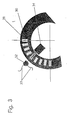
- the cuvettes 11 are positioned on a rotatable carousel or rotor, such as out Fig. 3 seen. From this also the favorable use of the pulse mode according to Fig. 2 Clearly, if a cuvette 11 is within a time interval ⁇ 1 in the range 32,34 accessible through the measuring optics, a pulse ( ⁇ 2) of one of the available light sources 1,2,2 can be triggered, the one above 33 and the coupling unit 32 on the cuvette 11th is applied. The signal obtained from this is detected within the time interval ⁇ 4.
Landscapes
- Physics & Mathematics (AREA)
- Immunology (AREA)
- Spectroscopy & Molecular Physics (AREA)
- Chemical & Material Sciences (AREA)
- Analytical Chemistry (AREA)
- Biochemistry (AREA)
- General Health & Medical Sciences (AREA)
- General Physics & Mathematics (AREA)
- Health & Medical Sciences (AREA)
- Life Sciences & Earth Sciences (AREA)
- Pathology (AREA)
- Investigating Or Analysing Materials By Optical Means (AREA)
- Investigating, Analyzing Materials By Fluorescence Or Luminescence (AREA)
- Spectrometry And Color Measurement (AREA)
- Investigating Or Analysing Biological Materials (AREA)
- Automatic Analysis And Handling Materials Therefor (AREA)
- Investigating Or Analysing Materials By The Use Of Chemical Reactions (AREA)
- Length Measuring Devices By Optical Means (AREA)
- Transmission Systems Not Characterized By The Medium Used For Transmission (AREA)
Claims (21)
- Dispositif pour effectuer des mesures optiques, comprenant un premier capteur ( 17 ), un deuxième capteur ( 25 ) et un troisième capteur ( 22 ), les capteurs étant propres à mesurer de la lumière, et un guidage commun de faisceau le long d'un axe ( 24 ) de faisceau ayant deux sources ( 1, 2 ) lumineuses couplées de domaines spectraux différents, pour guider la lumière sur l'emplacement de mesure souhaité, comprenant les éléments disposés dans l'ordre indiqué :a) au moins un diviseur ( 5 ) de faisceau dichroïque pour réunir la lumière de domaines spectraux différents issue des sources lumineuses,b) une cuvette ( 11 ) comme emplacement de mesure,c) un diaphragme ( 13 ),dans lequel le diaphragme (13) est constitué sous la forme d'un diaphragme annulaire et troué, qui, d'une part, laisse passer la lumière diffusée arrivant sur le diaphragme suivant une plage d'angles solides déterminée et, d'autre part, laisse passer la lumière transmise arrivant sur le diaphragme sous des angles petits d'environ 0° et dans lequel le premier capteur ( 17 ) mesure la lumière diffusée, le deuxième capteur ( 25 ) la lumière transmise et le troisième capteur ( 22 ) une partie de la lumière incidente comme témoin.
- Dispositif suivant la revendication 1, dans lequel l'une des sources (1, 2 ) lumineuses est constituée d'une source ( 1 ) émettant dans un domaine spectral UV-Vis, de préférence dans le domaine compris entre 320 et 750 nm.
- Dispositif suivant la revendication 1, dans lequel l'une des sources ( 1, 2 ) lumineuses est une source de lumière pulsée au xénon.
- Dispositif suivant la revendication 1, dans lequel l'une des sources ( 1, 2 ) lumineuses émet dans le domaine spectral rouge ou infrarouge ( NIR ), de préférence entre 600 et 900 nm.
- Dispositif suivant la revendication 1, dans lequel l'une des sources ( 1, 2 ) lumineuses est une diode laser ou une diode ( DEL ) électroluminescente.
- Dispositif suivant la revendication 5, dans lequel l'une des sources ( 1, 2 ) lumineuses est une DEL IR, qui émet dans le domaine compris entre 800 et 950 nm.
- Dispositif suivant l'une des revendications 1 à 6, dans lequel les sources ( 1, 2 ) lumineuses sont utilisées en mode pulsé.
- Dispositif suivant la revendication 1, dans lequel le guidage ( 24 ) commun de faisceau est constitué de fibres optiques souples.
- Dispositif suivant la revendication 1, muni d'un tiroir pour la réception de filtres, qui servent à l'étalonnage des sources lumineuses utilisées, en ce qui concerne leur longueur d'ondes ou leur absorption.
- Dispositif suivant la revendication 1, muni de diaphragmes ( 10, 16 ) pour la délimitation de la partie du faisceau disponible.
- Dispositif suivant la revendication 1, muni d'un miroir ( 8 ) semi-transparent pour la prise d'une proportion définie de la lumière incidente comme témoin.
- Dispositif suivant la revendication 1, dans lequel la lumière transmise est détectée sous des angles < 5° autour de la direction de propagation de la lumière incidente.
- Dispositif suivant la revendication 1, dans lequel la lumière transmise qui arrive est sortie du trajet du faisceau à l'aide d'une déviation ( 18 ) de faisceau.
- Dispositif suivant la revendication 13, dans lequel la déviation ( 18 ) de faisceau est constituée d'éléments optiques rigides ou de guides d'ondes lumineuses ayant des composants adéquats de raccordement.
- Dispositif suivant la revendication 1, dans lequel la lumière diffusée traversant le diaphragme ( 13 ) est projetée par un système de lentilles à l'entrée d'un détecteur ( 17 ).
- Dispositif suivant la revendication 1, muni de filtres ( 16 ) de séparation et de suppression de la lumière de domaine de longueurs d'ondes qui ne sont pas souhaitées.
- Dispositif suivant la revendication 1, muni de composants optoélectroniques pour la commande pulsée des sources lumineuses utilisées.
- Dispositif suivant la revendication 1, muni de composants ( 23, 26 ) électroniques d'amplification et de transformation des signaux pour un traitement ultérieur en technique de mesure.
- Dispositif suivant la revendication 1, muni d'une unité ( 27 ) de processeur pour la commande commune des composants, l'exploitation et la représentation des signaux.
- Dispositif suivant la revendication 1, par lequel la lumière diffusée et la lumière transmise peuvent être détectées sensiblement en même temps.
- Utilisation d'un dispositif suivant au moins l'une des revendications 1 à 20, dans un analyseur spectrophotométrique et néphélométrique dans le diagnostic in-vitro.
Applications Claiming Priority (2)
| Application Number | Priority Date | Filing Date | Title |
|---|---|---|---|
| DE19948587 | 1999-10-08 | ||
| DE19948587A DE19948587A1 (de) | 1999-10-08 | 1999-10-08 | Spektralphotometrische und nephelometrische Detektionseinheit |
Publications (3)
| Publication Number | Publication Date |
|---|---|
| EP1091205A2 EP1091205A2 (fr) | 2001-04-11 |
| EP1091205A3 EP1091205A3 (fr) | 2001-09-26 |
| EP1091205B1 true EP1091205B1 (fr) | 2011-02-16 |
Family
ID=7925001
Family Applications (1)
| Application Number | Title | Priority Date | Filing Date |
|---|---|---|---|
| EP00119806A Expired - Lifetime EP1091205B1 (fr) | 1999-10-08 | 2000-09-12 | Appareil de détection spectrophotométrique et néphélométrique |
Country Status (7)
| Country | Link |
|---|---|
| US (1) | US6791676B1 (fr) |
| EP (1) | EP1091205B1 (fr) |
| JP (1) | JP4791625B2 (fr) |
| AT (1) | ATE498836T1 (fr) |
| CA (1) | CA2322895C (fr) |
| DE (2) | DE19948587A1 (fr) |
| ES (1) | ES2359968T3 (fr) |
Cited By (1)
| Publication number | Priority date | Publication date | Assignee | Title |
|---|---|---|---|---|
| US10180248B2 (en) | 2015-09-02 | 2019-01-15 | ProPhotonix Limited | LED lamp with sensing capabilities |
Families Citing this family (36)
| Publication number | Priority date | Publication date | Assignee | Title |
|---|---|---|---|---|
| US7034942B2 (en) * | 2002-01-07 | 2006-04-25 | Hewlett-Packard Development Company, L.P. | Color measurement device and color measurement method |
| US20070054405A1 (en) * | 2003-10-23 | 2007-03-08 | Ortho-Clinical Diagnostics, Inc. | Patient sample classification based upon low angle light scattering |
| US7095500B2 (en) * | 2004-01-30 | 2006-08-22 | Nalco Company | Interchangeable tip-open cell fluorometer |
| ES2234441B1 (es) * | 2004-11-18 | 2006-02-16 | Grifols, S.A. | Aparato para la medicion de la absorbancia optica de muestras de liquidos, procedimiento y cubeta para su realizacion. |
| DE102005022880B4 (de) * | 2005-05-18 | 2010-12-30 | Olympus Soft Imaging Solutions Gmbh | Trennung spektral oder farblich überlagerter Bildbeiträge in einem Mehrfarbbild, insbesondere in transmissionsmikroskopischen Mehrfarbbildern |
| FR2907551A1 (fr) * | 2006-10-23 | 2008-04-25 | Bernard Pierre Andre Genot | Systeme d'analyse optique multifonctions |
| WO2009063322A2 (fr) * | 2007-08-15 | 2009-05-22 | Malvern Instruments Ltd | Spectromètre à grand parcours |
| DE202007016343U1 (de) * | 2007-11-19 | 2008-04-30 | Levin, Felix, Dr. | Vorrichtungssystem zur schnellen Bestimmung von Substanzen in Flüssigkeiten mit Hilfe eines Rechner-gekoppelten Videosystems |
| CN107132185B (zh) | 2008-02-05 | 2020-05-29 | 普凯尔德诊断技术有限公司 | 用于鉴定生物样品中细菌的系统 |
| DE102008061695A1 (de) | 2008-12-10 | 2010-06-17 | Laser- und Medizin-Technologie, Berlin GmbH | Anordnung zur Bestimmung optischer Eigenschaften bei mehreren Wellenlängen |
| US8852511B2 (en) | 2009-07-10 | 2014-10-07 | Hitachi High-Technologies Corporation | Automatic analyzer |
| US10288632B2 (en) * | 2009-09-21 | 2019-05-14 | Pocared Diagnostics Ltd. | System for conducting the identification of bacteria in biological samples |
| JP5379044B2 (ja) | 2010-02-25 | 2013-12-25 | 株式会社日立ハイテクノロジーズ | 自動分析装置 |
| JP5216051B2 (ja) | 2010-06-23 | 2013-06-19 | 株式会社日立ハイテクノロジーズ | 自動分析装置および自動分析方法 |
| EP2466292B1 (fr) * | 2010-10-29 | 2017-12-13 | F. Hoffmann-La Roche AG | Système permettant d'effectuer la diffusion et l'absorption d'analyses |
| US20130294974A1 (en) | 2010-12-08 | 2013-11-07 | Hitachi High-Technologies Corporation | Automatic analyzer |
| JP5822534B2 (ja) | 2011-05-13 | 2015-11-24 | 株式会社日立ハイテクノロジーズ | 自動分析装置 |
| TWI442031B (zh) * | 2011-06-17 | 2014-06-21 | Chroma Ate Inc | 光學量測系統及其裝置 |
| JP5740264B2 (ja) | 2011-09-20 | 2015-06-24 | 株式会社日立ハイテクノロジーズ | 自動分析装置及び分析方法 |
| JP5939833B2 (ja) | 2012-02-24 | 2016-06-22 | 株式会社日立ハイテクノロジーズ | 自動分析装置 |
| JP6013796B2 (ja) | 2012-06-25 | 2016-10-25 | 株式会社日立ハイテクノロジーズ | 自動分析装置及び試料測定方法 |
| JP5948173B2 (ja) | 2012-07-20 | 2016-07-06 | 株式会社日立ハイテクノロジーズ | 自動分析装置及び自動分析方法 |
| JP5932540B2 (ja) | 2012-07-24 | 2016-06-08 | 株式会社日立ハイテクノロジーズ | 自動分析装置 |
| JP6110710B2 (ja) | 2013-04-02 | 2017-04-05 | 株式会社日立ハイテクノロジーズ | 分析装置及び自動分析装置 |
| JPWO2014192963A1 (ja) | 2013-05-31 | 2017-02-23 | 積水メディカル株式会社 | 免疫凝集測定法 |
| JP6104746B2 (ja) * | 2013-07-23 | 2017-03-29 | 株式会社日立ハイテクノロジーズ | 自動分析装置および分析方法 |
| US9151672B2 (en) | 2013-11-21 | 2015-10-06 | Agilent Technologies, Inc. | Optical absorption spectrometry system including dichroic beam combiner and splitter |
| CN103822876B (zh) * | 2014-02-25 | 2017-01-04 | 深圳市清时捷科技有限公司 | 一种浊度测定仪及快速测定浊度的方法 |
| EP2957897A1 (fr) * | 2014-06-17 | 2015-12-23 | Siemens Healthcare Diagnostics Products GmbH | Scatteromètre doté d'un carrousel pour porte-échantillons cylindriques ou anguleux et d'un arrêt de faisceau pour lumière non diffusée qui est élargie de manière à recevoir la lumière non diffusée réfractée par le porte-échantillon |
| EP2957892A1 (fr) * | 2014-06-17 | 2015-12-23 | Siemens Healthcare Diagnostics Products GmbH | Système photométrique et procédé de détermination de position |
| ES2623452T3 (es) * | 2014-09-18 | 2017-07-11 | Siemens Healthcare Diagnostics Products Gmbh | Método y dispositivo para la determinación nefelométrica de un analito |
| JP6399520B2 (ja) * | 2015-03-16 | 2018-10-03 | 国立大学法人九州大学 | 光測定装置及び光測定方法 |
| EP3336495B1 (fr) * | 2016-12-16 | 2024-02-14 | F. Hoffmann-La Roche AG | Caractérisation des propriétés d'émission d'échantillons |
| CN111077073A (zh) * | 2018-10-19 | 2020-04-28 | 深圳迈瑞生物医疗电子股份有限公司 | 一种样本分析仪 |
| JP7181828B2 (ja) * | 2019-03-29 | 2022-12-01 | 古野電気株式会社 | 分析装置 |
| CN117629951A (zh) * | 2022-08-11 | 2024-03-01 | 深圳市帝迈生物技术有限公司 | 一种样本分析仪 |
Family Cites Families (26)
| Publication number | Priority date | Publication date | Assignee | Title |
|---|---|---|---|---|
| US3832062A (en) * | 1972-03-29 | 1974-08-27 | Den Bosch F Van | Spectrophotometrical apparatus for determining dosing substances in a liquid |
| DE2409273A1 (de) | 1974-02-27 | 1975-09-04 | Behringwerke Ag | Verfahren und vorrichtung zum messen von antigen-antikoerper-reaktionen |
| US4053229A (en) * | 1976-01-13 | 1977-10-11 | The United States Of America As Represented By The Administrator Of The National Aeronautics And Space Administration | 2°/90° Laboratory scattering photometer |
| US4325910A (en) * | 1979-07-11 | 1982-04-20 | Technicraft, Inc. | Automated multiple-purpose chemical-analysis apparatus |
| US4284355A (en) * | 1979-10-29 | 1981-08-18 | Ortho Diagnostics, Inc. | Automated method for cell volume determination |
| US4408880A (en) * | 1981-09-22 | 1983-10-11 | Chugai Seiyaku Kabushiki Kaisha | Laser nephelometric system |
| US4692883A (en) * | 1985-02-21 | 1987-09-08 | The Perkin-Elmer Corporation | Automatic digital wavelength calibration system for a spectrophotometer |
| US4730922A (en) * | 1985-05-08 | 1988-03-15 | E. I. Du Pont De Nemours And Company | Absorbance, turbidimetric, fluorescence and nephelometric photometer |
| FR2583164B1 (fr) * | 1985-06-06 | 1988-10-14 | Trapil Transports Petroliers P | Procede et dispositif pour determiner la couleur et la turbidite d'un fluide |
| GB8526355D0 (en) * | 1985-10-25 | 1985-11-27 | Alta Diagnostic Machines Ltd | Determination of antibody content of blood |
| US5104218A (en) * | 1989-11-09 | 1992-04-14 | General Atomics | Micropipette adaptor for spectrofluorimeters |
| JP2583653B2 (ja) * | 1990-02-23 | 1997-02-19 | 憲仁 丹保 | 液体中に含まれる複数成分の凝集過程を検出する方法とその装置 |
| US5646049A (en) * | 1992-03-27 | 1997-07-08 | Abbott Laboratories | Scheduling operation of an automated analytical system |
| US5348004A (en) * | 1993-03-31 | 1994-09-20 | Nellcor Incorporated | Electronic processor for pulse oximeter |
| US5400137A (en) * | 1993-08-11 | 1995-03-21 | Texaco Inc. | Photometric means for monitoring solids and fluorescent material in waste water using a stabilized pool water sampler |
| JPH07294429A (ja) * | 1994-04-27 | 1995-11-10 | Aretsuku Denshi Kk | 濁度計及び濁色度計 |
| US5959738A (en) * | 1994-07-25 | 1999-09-28 | Molecular Devices Corporation | Determination of light absorption pathlength in a vertical-beam photometer |
| US6104945A (en) * | 1995-08-01 | 2000-08-15 | Medispectra, Inc. | Spectral volume microprobe arrays |
| JPH0979975A (ja) * | 1995-09-12 | 1997-03-28 | Nakabootec:Kk | 防食皮膜の管理方法 |
| FI103434B1 (fi) * | 1996-04-22 | 1999-06-30 | Wallac Oy | Monileimamittauslaite |
| US5940178A (en) * | 1996-07-03 | 1999-08-17 | Beckman Instruments, Inc. | Nephelometer and turbidimeter combination |
| JPH11128176A (ja) * | 1997-10-29 | 1999-05-18 | Hitachi Ltd | 生体光計測装置 |
| DE19849597A1 (de) * | 1998-10-28 | 2000-05-04 | Dade Behring Marburg Gmbh | Nephelometrische Detektionseinheit mit optischer In-Prozeß-Kontrolle |
| JP2000230901A (ja) * | 1999-02-09 | 2000-08-22 | Mitsubishi Chemicals Corp | 光学ユニット |
| US6175750B1 (en) * | 1999-03-19 | 2001-01-16 | Cytometrics, Inc. | System and method for calibrating a reflection imaging spectrophotometer |
| FR2792725B1 (fr) * | 1999-04-23 | 2001-12-07 | Junior Instruments | Procede et dispositif pour la detection de variations de proprietes optiques d'un echantillon liquide dans un processus d'analyse |
-
1999
- 1999-10-08 DE DE19948587A patent/DE19948587A1/de not_active Ceased
-
2000
- 2000-09-12 AT AT00119806T patent/ATE498836T1/de active
- 2000-09-12 DE DE50016070T patent/DE50016070D1/de not_active Expired - Lifetime
- 2000-09-12 ES ES00119806T patent/ES2359968T3/es not_active Expired - Lifetime
- 2000-09-12 EP EP00119806A patent/EP1091205B1/fr not_active Expired - Lifetime
- 2000-10-06 JP JP2000307117A patent/JP4791625B2/ja not_active Expired - Fee Related
- 2000-10-06 US US09/680,436 patent/US6791676B1/en not_active Expired - Fee Related
- 2000-10-10 CA CA2322895A patent/CA2322895C/fr not_active Expired - Fee Related
Cited By (1)
| Publication number | Priority date | Publication date | Assignee | Title |
|---|---|---|---|---|
| US10180248B2 (en) | 2015-09-02 | 2019-01-15 | ProPhotonix Limited | LED lamp with sensing capabilities |
Also Published As
| Publication number | Publication date |
|---|---|
| EP1091205A2 (fr) | 2001-04-11 |
| US6791676B1 (en) | 2004-09-14 |
| ATE498836T1 (de) | 2011-03-15 |
| CA2322895A1 (fr) | 2001-04-08 |
| DE50016070D1 (de) | 2011-03-31 |
| JP2001141654A (ja) | 2001-05-25 |
| DE19948587A1 (de) | 2001-04-12 |
| CA2322895C (fr) | 2011-04-05 |
| ES2359968T3 (es) | 2011-05-30 |
| EP1091205A3 (fr) | 2001-09-26 |
| JP4791625B2 (ja) | 2011-10-12 |
Similar Documents
| Publication | Publication Date | Title |
|---|---|---|
| EP1091205A2 (fr) | Appareil de détection spectrophotométrique et néphélométrique | |
| EP0148497B1 (fr) | Dispositif pour conduire et collecter la lumière en photométrie | |
| DE69016027T2 (de) | Optischer Lesekopf für eine Immunoassay Vorrichtung. | |
| DE69422908T2 (de) | Optische vorrichtung fuer durchflusszytometer | |
| DE3724852C2 (de) | Absorptionsphotometer | |
| EP0470982B1 (fr) | Fluorimetre a reflection | |
| DE4441023C2 (de) | Gasanalysator nach dem Kreuzmodulations-Modus | |
| EP0938658A1 (fr) | Procede et dispositif de spectroscopie combinee par absorption et par reflectance | |
| CH618266A5 (en) | Spectrophotometer. | |
| EP3077793B1 (fr) | Dispositif d'analyse (photomètre) à guides de lumière en série | |
| DE3713149A1 (de) | Fernmess-spektrophotometer | |
| DE69012088T2 (de) | Optisches lesesystem. | |
| EP2533031A1 (fr) | Dispositif de mesure référencée de lumière réfléchie et procédé de calibrage d'un tel dispositif | |
| DE69023875T2 (de) | Vorrichtung zum Messen der Lichtabsorption oder Fluoreszenz in flüssigen Proben. | |
| DE69223377T2 (de) | Spektralphotometer zur Ausführung turbidimetrischer und kolorimetrischer Messungen | |
| DE60212910T2 (de) | Durchflusszellesystem zur Löslichkeitsprüfung | |
| DE2606481A1 (de) | Fluorometer | |
| DE60205406T2 (de) | Optisches zweiwellenlängen-fluoreszenzanalysegerät | |
| DE19824652A1 (de) | Vorrichtung zur Detektion von flüssigchromatographisch getrennten Substanzen mittels UV- oder Fluoreszenzspektren | |
| DE3938142C2 (fr) | ||
| EP0715166A1 (fr) | Méthode et dispositif pour contrÔler la contamination d'un bouteille à usage répété | |
| EP0427943B1 (fr) | Capteur à fibres optiques servant à la détection d'effets photothermiques | |
| WO2014053427A1 (fr) | Procédé de détection d'analytes | |
| DE19849597A1 (de) | Nephelometrische Detektionseinheit mit optischer In-Prozeß-Kontrolle | |
| EP3704473A1 (fr) | Capteur novateur pour spectroscopie raman |
Legal Events
| Date | Code | Title | Description |
|---|---|---|---|
| PUAI | Public reference made under article 153(3) epc to a published international application that has entered the european phase |
Free format text: ORIGINAL CODE: 0009012 |
|
| AK | Designated contracting states |
Kind code of ref document: A2 Designated state(s): AT BE CH CY DE DK ES FI FR GB GR IE IT LI LU MC NL PT SE |
|
| AX | Request for extension of the european patent |
Free format text: AL;LT;LV;MK;RO;SI |
|
| PUAL | Search report despatched |
Free format text: ORIGINAL CODE: 0009013 |
|
| AK | Designated contracting states |
Kind code of ref document: A3 Designated state(s): AT BE CH CY DE DK ES FI FR GB GR IE IT LI LU MC NL PT SE |
|
| AX | Request for extension of the european patent |
Free format text: AL;LT;LV;MK;RO;SI |
|
| RIC1 | Information provided on ipc code assigned before grant |
Free format text: 7G 01N 21/47 A, 7G 01N 21/31 B, 7G 01N 21/01 B, 7G 01N 21/51 B |
|
| 17P | Request for examination filed |
Effective date: 20020326 |
|
| AKX | Designation fees paid |
Free format text: AT BE CH CY DE DK ES FI FR GB GR IE IT LI LU MC NL PT SE |
|
| 17Q | First examination report despatched |
Effective date: 20070213 |
|
| RAP1 | Party data changed (applicant data changed or rights of an application transferred) |
Owner name: SIEMENS HEALTHCARE DIAGNOSTICS PRODUCTS GMBH |
|
| GRAP | Despatch of communication of intention to grant a patent |
Free format text: ORIGINAL CODE: EPIDOSNIGR1 |
|
| GRAS | Grant fee paid |
Free format text: ORIGINAL CODE: EPIDOSNIGR3 |
|
| GRAA | (expected) grant |
Free format text: ORIGINAL CODE: 0009210 |
|
| AK | Designated contracting states |
Kind code of ref document: B1 Designated state(s): AT BE CH CY DE DK ES FI FR GB GR IE IT LI LU MC NL PT SE |
|
| REG | Reference to a national code |
Ref country code: GB Ref legal event code: FG4D Free format text: NOT ENGLISH |
|
| REG | Reference to a national code |
Ref country code: CH Ref legal event code: EP |
|
| REG | Reference to a national code |
Ref country code: IE Ref legal event code: FG4D Free format text: LANGUAGE OF EP DOCUMENT: GERMAN |
|
| REF | Corresponds to: |
Ref document number: 50016070 Country of ref document: DE Date of ref document: 20110331 Kind code of ref document: P |
|
| REG | Reference to a national code |
Ref country code: DE Ref legal event code: R096 Ref document number: 50016070 Country of ref document: DE Effective date: 20110331 |
|
| REG | Reference to a national code |
Ref country code: ES Ref legal event code: FG2A Ref document number: 2359968 Country of ref document: ES Kind code of ref document: T3 Effective date: 20110530 |
|
| REG | Reference to a national code |
Ref country code: NL Ref legal event code: VDEP Effective date: 20110216 |
|
| PG25 | Lapsed in a contracting state [announced via postgrant information from national office to epo] |
Ref country code: GR Free format text: LAPSE BECAUSE OF FAILURE TO SUBMIT A TRANSLATION OF THE DESCRIPTION OR TO PAY THE FEE WITHIN THE PRESCRIBED TIME-LIMIT Effective date: 20110517 Ref country code: PT Free format text: LAPSE BECAUSE OF FAILURE TO SUBMIT A TRANSLATION OF THE DESCRIPTION OR TO PAY THE FEE WITHIN THE PRESCRIBED TIME-LIMIT Effective date: 20110616 Ref country code: SE Free format text: LAPSE BECAUSE OF FAILURE TO SUBMIT A TRANSLATION OF THE DESCRIPTION OR TO PAY THE FEE WITHIN THE PRESCRIBED TIME-LIMIT Effective date: 20110216 |
|
| PG25 | Lapsed in a contracting state [announced via postgrant information from national office to epo] |
Ref country code: CY Free format text: LAPSE BECAUSE OF FAILURE TO SUBMIT A TRANSLATION OF THE DESCRIPTION OR TO PAY THE FEE WITHIN THE PRESCRIBED TIME-LIMIT Effective date: 20110216 Ref country code: FI Free format text: LAPSE BECAUSE OF FAILURE TO SUBMIT A TRANSLATION OF THE DESCRIPTION OR TO PAY THE FEE WITHIN THE PRESCRIBED TIME-LIMIT Effective date: 20110216 Ref country code: NL Free format text: LAPSE BECAUSE OF FAILURE TO SUBMIT A TRANSLATION OF THE DESCRIPTION OR TO PAY THE FEE WITHIN THE PRESCRIBED TIME-LIMIT Effective date: 20110216 |
|
| REG | Reference to a national code |
Ref country code: IE Ref legal event code: FD4D |
|
| PG25 | Lapsed in a contracting state [announced via postgrant information from national office to epo] |
Ref country code: IE Free format text: LAPSE BECAUSE OF FAILURE TO SUBMIT A TRANSLATION OF THE DESCRIPTION OR TO PAY THE FEE WITHIN THE PRESCRIBED TIME-LIMIT Effective date: 20110216 Ref country code: DK Free format text: LAPSE BECAUSE OF FAILURE TO SUBMIT A TRANSLATION OF THE DESCRIPTION OR TO PAY THE FEE WITHIN THE PRESCRIBED TIME-LIMIT Effective date: 20110216 |
|
| PLBE | No opposition filed within time limit |
Free format text: ORIGINAL CODE: 0009261 |
|
| STAA | Information on the status of an ep patent application or granted ep patent |
Free format text: STATUS: NO OPPOSITION FILED WITHIN TIME LIMIT |
|
| 26N | No opposition filed |
Effective date: 20111117 |
|
| REG | Reference to a national code |
Ref country code: DE Ref legal event code: R097 Ref document number: 50016070 Country of ref document: DE Effective date: 20111117 |
|
| BERE | Be: lapsed |
Owner name: SIEMENS HEALTHCARE DIAGNOSTICS PRODUCTS G.M.B.H. Effective date: 20110930 |
|
| PG25 | Lapsed in a contracting state [announced via postgrant information from national office to epo] |
Ref country code: MC Free format text: LAPSE BECAUSE OF NON-PAYMENT OF DUE FEES Effective date: 20110930 |
|
| REG | Reference to a national code |
Ref country code: CH Ref legal event code: PL |
|
| PG25 | Lapsed in a contracting state [announced via postgrant information from national office to epo] |
Ref country code: IT Free format text: LAPSE BECAUSE OF FAILURE TO SUBMIT A TRANSLATION OF THE DESCRIPTION OR TO PAY THE FEE WITHIN THE PRESCRIBED TIME-LIMIT Effective date: 20110216 |
|
| PG25 | Lapsed in a contracting state [announced via postgrant information from national office to epo] |
Ref country code: BE Free format text: LAPSE BECAUSE OF NON-PAYMENT OF DUE FEES Effective date: 20110930 |
|
| PG25 | Lapsed in a contracting state [announced via postgrant information from national office to epo] |
Ref country code: CH Free format text: LAPSE BECAUSE OF NON-PAYMENT OF DUE FEES Effective date: 20110930 Ref country code: LI Free format text: LAPSE BECAUSE OF NON-PAYMENT OF DUE FEES Effective date: 20110930 |
|
| REG | Reference to a national code |
Ref country code: AT Ref legal event code: MM01 Ref document number: 498836 Country of ref document: AT Kind code of ref document: T Effective date: 20110912 |
|
| PG25 | Lapsed in a contracting state [announced via postgrant information from national office to epo] |
Ref country code: AT Free format text: LAPSE BECAUSE OF NON-PAYMENT OF DUE FEES Effective date: 20110912 |
|
| PGFP | Annual fee paid to national office [announced via postgrant information from national office to epo] |
Ref country code: DE Payment date: 20121119 Year of fee payment: 13 |
|
| PG25 | Lapsed in a contracting state [announced via postgrant information from national office to epo] |
Ref country code: LU Free format text: LAPSE BECAUSE OF NON-PAYMENT OF DUE FEES Effective date: 20110912 |
|
| PGFP | Annual fee paid to national office [announced via postgrant information from national office to epo] |
Ref country code: GB Payment date: 20130911 Year of fee payment: 14 Ref country code: FR Payment date: 20130924 Year of fee payment: 14 |
|
| PGFP | Annual fee paid to national office [announced via postgrant information from national office to epo] |
Ref country code: ES Payment date: 20131004 Year of fee payment: 14 |
|
| REG | Reference to a national code |
Ref country code: DE Ref legal event code: R119 Ref document number: 50016070 Country of ref document: DE Effective date: 20140401 |
|
| PG25 | Lapsed in a contracting state [announced via postgrant information from national office to epo] |
Ref country code: DE Free format text: LAPSE BECAUSE OF NON-PAYMENT OF DUE FEES Effective date: 20140401 |
|
| GBPC | Gb: european patent ceased through non-payment of renewal fee |
Effective date: 20140912 |
|
| REG | Reference to a national code |
Ref country code: FR Ref legal event code: ST Effective date: 20150529 |
|
| PG25 | Lapsed in a contracting state [announced via postgrant information from national office to epo] |
Ref country code: GB Free format text: LAPSE BECAUSE OF NON-PAYMENT OF DUE FEES Effective date: 20140912 |
|
| PG25 | Lapsed in a contracting state [announced via postgrant information from national office to epo] |
Ref country code: FR Free format text: LAPSE BECAUSE OF NON-PAYMENT OF DUE FEES Effective date: 20140930 |
|
| REG | Reference to a national code |
Ref country code: ES Ref legal event code: FD2A Effective date: 20151026 |
|
| PG25 | Lapsed in a contracting state [announced via postgrant information from national office to epo] |
Ref country code: ES Free format text: LAPSE BECAUSE OF NON-PAYMENT OF DUE FEES Effective date: 20140913 |