EP1091441B1 - Resonatorvorrichtung, Filter, zusammengestelltes Filter, Duplexer und Kommunikationsgerät - Google Patents
Resonatorvorrichtung, Filter, zusammengestelltes Filter, Duplexer und Kommunikationsgerät Download PDFInfo
- Publication number
- EP1091441B1 EP1091441B1 EP00121698A EP00121698A EP1091441B1 EP 1091441 B1 EP1091441 B1 EP 1091441B1 EP 00121698 A EP00121698 A EP 00121698A EP 00121698 A EP00121698 A EP 00121698A EP 1091441 B1 EP1091441 B1 EP 1091441B1
- Authority
- EP
- European Patent Office
- Prior art keywords
- cavity
- mode
- dielectric core
- quasi
- resonator
- Prior art date
- Legal status (The legal status is an assumption and is not a legal conclusion. Google has not performed a legal analysis and makes no representation as to the accuracy of the status listed.)
- Expired - Lifetime
Links
- 238000004891 communication Methods 0.000 title claims description 11
- 239000002131 composite material Substances 0.000 title claims description 8
- 239000004020 conductor Substances 0.000 claims description 101
- 230000005540 biological transmission Effects 0.000 claims description 16
- 230000008878 coupling Effects 0.000 description 48
- 238000010168 coupling process Methods 0.000 description 48
- 238000005859 coupling reaction Methods 0.000 description 48
- 230000008859 change Effects 0.000 description 20
- 230000005684 electric field Effects 0.000 description 20
- 239000013598 vector Substances 0.000 description 17
- 239000000463 material Substances 0.000 description 15
- 238000009826 distribution Methods 0.000 description 11
- XEEYBQQBJWHFJM-UHFFFAOYSA-N Iron Chemical compound [Fe] XEEYBQQBJWHFJM-UHFFFAOYSA-N 0.000 description 8
- 230000005672 electromagnetic field Effects 0.000 description 8
- 230000003068 static effect Effects 0.000 description 7
- 229910052782 aluminium Inorganic materials 0.000 description 6
- XAGFODPZIPBFFR-UHFFFAOYSA-N aluminium Chemical compound [Al] XAGFODPZIPBFFR-UHFFFAOYSA-N 0.000 description 6
- 239000007769 metal material Substances 0.000 description 6
- RYGMFSIKBFXOCR-UHFFFAOYSA-N Copper Chemical compound [Cu] RYGMFSIKBFXOCR-UHFFFAOYSA-N 0.000 description 5
- 229910052802 copper Inorganic materials 0.000 description 5
- 239000010949 copper Substances 0.000 description 5
- 230000003247 decreasing effect Effects 0.000 description 5
- 238000000034 method Methods 0.000 description 5
- 229910001374 Invar Inorganic materials 0.000 description 4
- 229910052742 iron Inorganic materials 0.000 description 4
- 229910052594 sapphire Inorganic materials 0.000 description 4
- 239000010980 sapphire Substances 0.000 description 4
- 239000000919 ceramic Substances 0.000 description 3
- 238000010586 diagram Methods 0.000 description 3
- 239000003989 dielectric material Substances 0.000 description 3
- 230000005855 radiation Effects 0.000 description 3
- IJGRMHOSHXDMSA-UHFFFAOYSA-N Atomic nitrogen Chemical compound N#N IJGRMHOSHXDMSA-UHFFFAOYSA-N 0.000 description 2
- GWEVSGVZZGPLCZ-UHFFFAOYSA-N Titan oxide Chemical compound O=[Ti]=O GWEVSGVZZGPLCZ-UHFFFAOYSA-N 0.000 description 2
- 230000015572 biosynthetic process Effects 0.000 description 2
- 238000005266 casting Methods 0.000 description 2
- 230000006866 deterioration Effects 0.000 description 2
- 238000003379 elimination reaction Methods 0.000 description 2
- 229910052738 indium Inorganic materials 0.000 description 2
- APFVFJFRJDLVQX-UHFFFAOYSA-N indium atom Chemical compound [In] APFVFJFRJDLVQX-UHFFFAOYSA-N 0.000 description 2
- 239000011347 resin Substances 0.000 description 2
- 229920005989 resin Polymers 0.000 description 2
- 238000005476 soldering Methods 0.000 description 2
- 229910001220 stainless steel Inorganic materials 0.000 description 2
- 239000010935 stainless steel Substances 0.000 description 2
- BFTGQIQVUVTBJU-UHFFFAOYSA-N 5,6-dihydroimidazo[2,1-c][1,2,4]dithiazole-3-thione Chemical compound C1CN2C(=S)SSC2=N1 BFTGQIQVUVTBJU-UHFFFAOYSA-N 0.000 description 1
- 229910001369 Brass Inorganic materials 0.000 description 1
- 230000002238 attenuated effect Effects 0.000 description 1
- 239000010951 brass Substances 0.000 description 1
- 230000001413 cellular effect Effects 0.000 description 1
- 229910010293 ceramic material Inorganic materials 0.000 description 1
- 230000000694 effects Effects 0.000 description 1
- 239000007788 liquid Substances 0.000 description 1
- 238000001465 metallisation Methods 0.000 description 1
- 238000010295 mobile communication Methods 0.000 description 1
- 238000000465 moulding Methods 0.000 description 1
- 229910052757 nitrogen Inorganic materials 0.000 description 1
- 238000007747 plating Methods 0.000 description 1
- 230000000644 propagated effect Effects 0.000 description 1
- 230000009467 reduction Effects 0.000 description 1
- 230000004044 response Effects 0.000 description 1
- 230000000630 rising effect Effects 0.000 description 1
- 229910000679 solder Inorganic materials 0.000 description 1
- 125000006850 spacer group Chemical group 0.000 description 1
- 229910052718 tin Inorganic materials 0.000 description 1
- 229910052726 zirconium Inorganic materials 0.000 description 1
Images


Classifications
-
- H—ELECTRICITY
- H01—ELECTRIC ELEMENTS
- H01P—WAVEGUIDES; RESONATORS, LINES, OR OTHER DEVICES OF THE WAVEGUIDE TYPE
- H01P7/00—Resonators of the waveguide type
- H01P7/04—Coaxial resonators
-
- H—ELECTRICITY
- H01—ELECTRIC ELEMENTS
- H01P—WAVEGUIDES; RESONATORS, LINES, OR OTHER DEVICES OF THE WAVEGUIDE TYPE
- H01P1/00—Auxiliary devices
- H01P1/20—Frequency-selective devices, e.g. filters
- H01P1/201—Filters for transverse electromagnetic waves
- H01P1/205—Comb or interdigital filters; Cascaded coaxial cavities
- H01P1/2053—Comb or interdigital filters; Cascaded coaxial cavities the coaxial cavity resonators being disposed parall to each other
Definitions
- the present invention relates to a resonator device in which plural resonance modes are multiplexed, a method of producing the same, a filter, a composite filter device, a duplexer, and a communication device including them.
- resonators to be operated with a relatively large power in a microwave band cavity resonators and re-entrant cylindrical cavity resonators re-entrant resonators have been used.
- the re-entrant cylindrical cavity resonator is also called a coaxial cavity resonator.
- the Q value is relatively high, and the size is smaller than that of the cavity resonator. Therefore, the re-entrant cylindrical cavity resonator has been effective in reducing the size of the configuration of a filter.
- microcells being employed in cellular mobile communication systems, e.g., in mobile telephones and so forth, it has been more strongly required to reduce the size of filters for use in base stations.
- the sapphire resonator consists of a sapphire ring separated into two parts with webs on the outer hand of each to form two re-entrant parts which are separated by a copper post.
- the re-entrant parts are bonded to the post by indium solder for good thermal conductivity between parts of that subassembly which is supported on the base plate of a closed copper cylinder (rf shielding casing) by a thin stainless steel cylinder.
- a unit for temperature control is placed in the stainless steel cylinder and is connected to the subassembly of re-entrant parts and copper post by a layer of indium for good thermal conduction.
- the rf shielding casing is placed in a vacuum tank which is in turn placed in a thermos flask of liquid nitrogen.
- the temperature regulator is controlled from outside the thermos flask to a temperature in a range of about 40° to 150° K, such as 87° K for the WGH 811 mode of resonance in response to microwave energy inserted into the rf shielding casing through a port from an outside source.
- the coaxial resonators are partly filled with dielectric round their inner conductors.
- the dielectric is provided with a metallised surface on each coaxial resonator.
- the metallised surfaces are interconnected by a conductor, passed through an opening in the outer wall, pref. between the dielectric and the outer wall is an air gap.
- one or several tuning screws protrude into the coaxial resonators, taking part in the coupling, via the metallised surfaces.
- a resonator device in which the structure of a re-entrant cylindrical cavity resonator or coaxial resonator is partially adopted, which can be configured in a small size as a whole, even when the number of resonator stages is increased, a filter, a composite filter device, a duplexer, and a communication device using them.
- the resonator device in accordance with the present invention comprises a conductive rod provided in a conductive cavity with at least one end of the rod being electrically connected to the cavity, and a dielectric core provided in the cavity.
- the mode of a re-entrant cylindrical cavity resonator is caused by the cavity and the conductor rod, a resonance mode such as a TM mode is caused by the cavity and the dielectric core, or a resonance mode such as a TE mode is caused by the dielectric core.
- resonators can be multiplexed in one cavity.
- the size of the device can be reduced.
- a hole is formed in the dielectric core, and the rod is inserted in and through the hole.
- the dielectric core can be disposed in an optional position, e.g., in the center of the cavity.
- the dielectric core may be bonded to the inner surface of the cavity.
- the capacitance component which determines the resonance frequency in the resonance mode caused by the cavity and the dielectric core can be increased.
- the dielectric core is supported on a stand in the cavity, and the dielectric core is spaced from the inner surface of the cavity.
- the capacitance component which determines the resonance frequency in the resonance mode caused by the dielectric core can be decreased.
- the resonance modes caused by the cavity and the dielectric core are made a duplex TM mode, which is coupled to the mode of the re-entrant cylindrical cavity resonator to be made triplex.
- a method of producing a resonator according to the present invention comprises the steps of selecting such a material of the dielectric core that the change of the resonance frequency in the resonance mode caused by the cavity and the dielectric core can be made substantially constant for changes in temperature, and selecting such a material of the rod that the change of the resonance frequency in the resonance mode caused by the cavity and the rod can be made substantially constant for changes in temperature.
- an input-output conductor is provided in the resonator device having the above-described structure to be coupled to a predetermined mode of the above resonance modes and carry out input-output of a signal.
- the composite filter device of the present invention comprises plural sets of the filters.
- the duplexer of the present invention comprises two sets of the filters, in which the input port of the first filter is an input port for a transmission signal, the output port of the second filter is an output port for a reception signal, and the input-output port shared by the first and second filters is an antenna port.
- the communication device of the present invention is formed by use of the filter, the composite filter device, or the duplexer.
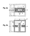
- Fig. 1 is an exploded perspective view of the resonator device.
- the resonator device contains a cavity body 1 having a substantially rectangular parallelepiped shape of which the upper side is open, and the underside is closed, and a cavity lid 2 covering the open upper side of the cavity body 1.
- a conductor rod 4 is formed so as to protrude from the center of the inner bottom of the cavity body 1, elongating in parallel to the respective inner walls of the cavity body 1.
- a dielectric core 3 having a substantially rectangular parallelepiped shape is provided, which has a hole which the conductor rod 4 is inserted in and through.
- Fig. 2A is a plan view of the resonator device before the cavity lid 2 is attached.
- Fig. 2B is a central, longitudinal cross section of the resonator device having the cavity lid 2 attached thereto.
- the conductor rod 4 is formed integrally with the cavity body 1, and has such a length that a predetermined gap is produced between the top of the conductor rod 4 and the inner surface of the cavity lid 2.
- Both of the end-faces in the longitudinal direction of the dielectric core 3 are bonded to the inner walls of the cavity body 1, respectively.
- Ag electrodes are formed by metallization on both of the end-faces of the dielectric core 3, and are bonded by soldering to the inner walls of the cavity body 1, respectively.
- the cavity body 1 and the cavity lid 2 are formed by casting or cutting a metallic material, or for the formation, a conductor film is applied on a ceramic or resin.
- the conductor rod 4 may be formed separately from the cavity body 1 and fixed to the cavity body 1 by screwing, soldering, or the like.
- the conductor rod 4 may be provided, separately from the cavity lid 2 or integrally with the cavity lid 2.
- the conductor rod 4 may be formed by casting or cutting a metallic material, or for the formation, a conductor film may be applied on the surface of a ceramic or resin, similarly to the cavity body 1 and the cavity lid 2.
- Figs. 3A, 3B, and 3C show examples of the electromagnetic field distributions in the respective modes of the resonator device.
- the solid line arrows indicate electric field vectors
- the broken line arrows indicate magnetic field vectors.
- Fig. 3A illustrates an electromagnetic field distribution in the TM mode, caused by the dielectric core 3 and the cavity. In this mode, the electric field vector is directed in the longitudinal direction of the dielectric core 3. The magnetic vector draws a loop in a plane perpendicular to the longitudinal direction of the dielectric core 3.
- the dielectric core 3 has a rectangular parallelepiped shape, a circular cylindrical coordinates system is employed as the representation of a mode.
- the numbers of waves in the respective electric field intensity distributions are represented by the sequence TM ⁇ rh, in which h represents the number of waves in the propagation direction, ⁇ represents the number of waves in the in-plane turning direction in a plane perpendicular to the propagation direction, and r represents the number of waves in the in-plane radiation (radial) direction in a plane perpendicular to the propagation direction.
- this mode is represented by TMO1O mode.
- the dielectric core 3 is not circle-cylindrical, and the conductor rod 4 is disposed in the center of the dielectric core 3. Therefore, practically, this mode is similar to the TMO10 mode, and hereinafter, is referred to as "quasi-TM mode".
- Figs. 3B and 3C are a plan view and a front view of the re-entrant cylindrical cavity resonator in a mode caused by the cavity and the conductor rod 4.
- the electric field vector is directed in the radial direction from the conductor rod 4 to the inner walls of the cavity.
- the magnetic field vector draws a loop in the turning-around direction with respect to the conductor rod 4.
- the dielectric core 3 is charged, and the top of the conductor rod 4 and the top-plane of the cavity has a gap therebetween.
- this mode is named a quasi-TEM mode.
- the resonance frequency in the quasi-TM mode is 1910 MHz, and that of the quasi-TEM mode is 2155 MHz.
- this device can be uses as a 2 GHz band resonator.
- the quasi-TM mode and the quasi-TEM mode shown in Figs. 3A, 3B, and 3C are not coupled together, since the electric field intensities in the longitudinal direction of the dielectric core 3 are balanced with each other. However, by unbalancing the electric field intensities in these two modes, the modes can be coupled together.
- Fig. 4 illustrates an example of the structure by which the above-mentioned two modes can be coupled together.
- Fig. 4 is a plan view of the resonator device prior to the attachment of the cavity lid 2.
- the electric field vector E TEM in the quasi-TEM mode is directed in the radial direction from the conductor rod 4
- the electric field vector E TM in the quasi-TM mode is directed in the longitudinal direction of the dielectric core 3. Accordingly, both of the modes are coupled to each other by disturbing the balance of the electric field intensity in the range of from one end in the longitudinal direction of the dielectric core 3 to the center thereof (the conductor rod 4 portion) with that in the range of from the other end to the center.
- the conductor rod 4 portion the electric field vector
- a coupling adjustment hole h is provided, so that the symmetry of the electric field intensity is lost in the vicinity of the hole h, and thereby, the quasi-TEM mode and the quasi-TM mode are coupled together.
- the coupling degree is determined by the size (inner diameter or depth) of the coupling adjustment hole h.
- a gap is provided between the hole in the center of the dielectric core 3 and the conductor rod 4. This suppresses the conductor loss which will be caused by current flowing in the conductor rod 4, and enhances the Q value of the resonator.
- the above-mentioned gap is not essential.
- the wall of the hole in the center of the dielectric core 3 may be bonded to the conductor rod 4.
- Figs. 5A and 5B show the structure of a resonator device according to a second embodiment of the present invention.
- Fig. 5A is a plan view of the resonator device before the cavity lid 2 is attached.
- Fig. 5B is a longitudinal cross section of the resonator device.
- the end-faces of the dielectric core 3 are spaced from the inner walls of the cavity, as is different from the first embodiment.
- a stand 5 for supporting the dielectric core 3 is provided.
- the stand 5 is made of a ceramic material having a low dielectric constant, is formed into a cylindrical shape, and is bonded to the dielectric core 3.
- the conductor rod 4 is inserted in and through the dielectric core 3 having the stand 5 attached thereto, whereby the dielectric core 3 is fixed substantially in the center of the cavity.
- this resonance mode can be expressed as TM01 ⁇ mode.
- ⁇ is a figure less than 1, namely, it represents that a wave are not completely propagated in the above-mentioned propagation direction, and a change in the intensity is generated.
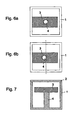
- Figs. 6A and 6B show two examples of the configuration of a resonator according to a third embodiment of the present invention. These figures are plan views of the resonator device before the cavity lid is attached thereto. In each example, one end-face in the longitudinal direction of the dielectric core 3 is bonded to the inner wall of the cavity body 1, while the other end is spaced from the inner wall of the cavity. In such a structure, a resonator device having a characteristic which is intermediate between the characteristic of the resonator device having both of the ends in the longitudinal direction of the dielectric core 3 bonded to the inner walls of the cavity and the characteristic of the resonator device having both of the ends of the dielectric core spaced from the inner walls of the cavity, respectively. Accordingly, a resonator having a small whole-size and having a high Q value can be obtained.
- the conductor rod 4 is disposed on the center axis of the cavity.
- the conductor rod 4 may be inserted in and through the center portion of the dielectric core 3, so that the conductor rod 4 is disposed in a position departing from the center axis of the cavity.
- the cavity and the conductor rod 4 are not necessarily coaxial. Even if the axes of the cavity and the conductor rod 4 are different from each other, the resonator device of the present invention functions as a so-called re-entrant cylindrical cavity resonator.
- Fig. 7 is a longitudinal cross section of a resonator device according to a fourth embodiment of the present invention.
- the conductor rod 4 is inserted in and through the hole formed in the dielectric core 3.
- the dielectric core 3 may be disposed between the top of the conductor rod 4 and the inner surface of the cavity opposed to the top of the conductor rod 4 (in this example, the underside of the cavity lid 3), as shown in Fig. 7 .
- the dielectric core 3 can be easily molded. If the dielectric core 3 is bonded to the top of the conductor rod 4 as in the embodiment of Fig. 7 , the dielectric core 3 can be fixed without a stand being provided.
- Fig. 8 is a perspective view showing the structure of the dielectric core 3 of a resonator device according to a fifth embodiment of the present invention.
- the shape of the dielectric core 3, together with the cavity, constituting the resonator in the quasi-TM mode is not limited to a rectangular parallelepiped.
- the shape may be another polyhedron except for a hexahedron, and also, may be columnar.
- Figs. 9A, 9B, and 9C are examples of the shapes in cross section of different cavities of a resonator device according to a sixth embodiment of the present invention.
- the shape in cross section of a cavity, taken in a plane perpendicular to the axial direction of the cavity is not limited to a square.
- the shape may be a polygon as shown in Fig. 9A , or may be circular as shown in Fig. 9B .
- the inner wall of the cavity may be a combination of curved and flat planes, as shown in Fig. 9C .
- the shape of the conductor rod 4 is not limited to a circle, and may be a prism, as shown in Fig. 9B . If the dielectric core 3 is provided with an angular hole corresponding to the shape of the conductor rod 4, the dielectric core 3 can be located in the axial direction by engagement of the dielectric core 3 with the conductor rod 4.
- Fig. 10A is a plan view of the resonator device before the cavity lid 2 is attached thereto.
- Fig. 10B is a center longitudinal cross section of the resonator device having the cavity lid 2 attached thereto.
- the top of the conductor rod 4 is electrically connected to the inner surface of the cavity lid 2.
- the cavity defined by the conductor rod 4, the conductor rod 4, and the cavity composed of the cavity body 1 and the cavity lid 2 constitute a coaxial cavity resonator.
- the coaxial cavity resonator acts as a half wave coaxial cavity resonator.
- the resonance frequency in the TM010 mode is 1349 MH, and that in the TEM mode is 1585 MHz.
- Fig. 11 is an exploded perspective view of the resonator device.
- the conductor rod 4 is provided on the center axis of the cavity body 1.
- the dielectric core 3 is provided in the cavity body 1 in such a manner that the conductor rod 4 is inserted in and through a hole formed in the dielectric core 3.
- the cavity lid 2 is attached to the open upper side of the cavity body 1.
- Fig. 12A is a plane view of the resonator device prior to the attachment of the cavity lid 2.
- Fig. 12B is a longitudinal cross section thereof.
- the resonator in the single quasi-TM mode is formed.
- a resonator in double quasi-TM modes is formed of which the cross section in a plane perpendicular to the conductor rod or the axis of the quasi-TEM mode is a square.
- Figs. 13A, 13B, and 13C illustrate examples of the electromagnetic field distributions in three resonance modes.
- Figs. 13A and 13B show the TM010 -x mode and the TM010 -y mode, respectively. These two modes have a degenerate relation to each other.
- Fig. 13C shows the electromagnetic field distribution in the quasi-TEM mode, caused by the cavity and the conductor rod 4.
- the solid line arrows represent the electric field vector
- the broken line arrows represent the magnetic field vector.
- a circular cylindrical coordinate system is employed as the representation of a mode.
- the numbers of waves in the respective electric field intensity distributions are represented by the sequence of TM ⁇ rh, in which h represents the number of waves in the propagation direction, ⁇ represents the number of waves in the in-plane turning-around direction in a plane perpendicular to the propagation direction, and r represents the number of waves in the in-plane radiation (radial) direction in a plane perpendicular to the propagation direction.
- the propagation direction is represented by a subscript.
- the magnetic field vector turns in parallel to the y-z plane of the dielectric core 3.
- the magnetic field vector turns in parallel to the x-z plane of the dielectric core 3.
- Fig. 14 shows an example of a structure for coupling the above three modes arbitrarily.
- a coupling adjustment hole h1 for coupling the above quasi-TEM mode and the TM010 -x mode is provided.
- the hole h1 is provided at one of symmetric positions with respect to the conductor rod 4 in the direction in which the electric field vectors in the TM010 -x mode and the quasi-TEM mode are directed in parallel to each other. Thereby, the balance at the symmetric positions of the electric field intensity in the quasi-TEM mode with that in the TM010 -x mode is disturbed, so that both of the modes are coupled together.
- a coupling adjustment hole h2 for coupling the above-mentioned quasi-TEM mode and the TM010 -y mode together is provided.
- the hole h2 is provided at one of symmetric positions with respect to the conductor rod 4 in the direction in which the electric field vectors in the TM010 -y mode and the quasi-TEM mode are directed in parallel to each other. Thereby, the balance at the symmetric positions of the electric field intensity in the quasi-TEM mode with that in the TM010 -y mode is disturbed, so that both of the modes are coupled together.
- a coupling adjustment hole h3 for coupling the TM010 -x and TM010 -y together is provided.
- the coupling adjustment hole h3 With the coupling adjustment hole h3, a difference is caused between the resonance frequencies in the odd mode and the even mode which are produced by coupling both of the two modes. Thereby, the degenerate relation of both of the modes is solved, so that the both of the modes are coupled to each other.
- Figs. 15A and 15B show two examples of a filter comprising three stage filters, formed by coupling the above-described three resonance modes.
- the intensity of the magnetic field in the TEM mode is stronger in the lower part of the resonator, and the intensity of the magnetic field in the TM mode is weaker at a position more distant from the dielectric core 3.
- the magnetic field in the quasi-TEM mode caused by the conductor rod 4 and the cavity, is passed through a coupling loop 10a.
- the coupling loop 10a is coupled to the quasi-TEM mode.
- the coupling degree of the coupling loop 10a and the TM mode is so small as to be negligible.
- the magnetic filed in the TM010 -x mode is passed through a coupling loop 10b.
- the coupling loop 10b is coupled to the TM010 -x mode.
- the coupling adjustment hole h2 causes the quasi-TEM mode and the TM010 -x mode to couple together.
- the coupling adjustment hole h2 causes the TM010 -x mode and the TM010 -y mode to be coupled together.
- the coupling adjustment hole h3 causes the TM010 -x mode and the TM010 -y mode to couple together.
- this device functions as a filter composed of three stage resonators.
- the magnetic field in the TM010 -y mode is passed through the coupling loop 10a.
- the coupling loop 10a is coupled to the TM010 -y mode.
- the magnetic field in the TM010 -x mode is passed through the coupling loop 10b.
- the coupling loop 10b is coupled to the TM010 -x mode.
- the coupling adjustment hole h1 causes the quasi-TEM mode and the TM010 -x mode to couple together.
- the coupling adjustment hole h2 causes the quasi-TEM mode and the TM010 -y mode to couple together.
- this device functions as a filter composed of three stage filters.
- the resonance frequencies in the TM010 -x mode, the TM010 -y mode, and the quasi-TEM mode are 1072 MHz, 1072 MHz, and 983 MHz, respectively.
- Fig. 16A is a plan view of the resonator prior to the attachment of the cavity lid 2.
- Fig. 16B is a center longitudinal cross section of the resonator having the cavity lid 2 attached thereto.
- the top of the conductor rod 4 is electrically connected to the inner surface of the cavity lid 2. Accordingly, the conductor rod 4, the cavity body 1, and the cavity lid 2 constitute a coaxial cavity resonator.
- This coaxial cavity resonator functions as a half-wave coaxial cavity resonator.
- the resonance frequencies in the TM010 -x mode, the TM010 -y mode, and the TEM mode are 2047 MHz, 2047 MHz, and 1970 MHz.
- Figs. 17A and 17B to 19A, 19B, and 19C show examples of various structures of the dielectric core 3 of a resonator device according to a tenth embodiment of the present invention, and examples of various types of attachment of the dielectric core 3 inside of the cavity.
- the dielectric core 3 has a cross shape.
- the dielectric core 3 takes a square shape of which the four corners are cut off. In these shapes, the area where each dielectric core contacts with the cavity is reduced. Thus, deterioration of the Q value in the conductor can be prevented.
- the faces of the dielectric core 3 are spaced from the inner walls in two directions of the cavity.
- the dielectric core 3 having a square sheet shape is used.
- the dielectric core 3 having a cross shape is used.
- the dielectric core 3 having an octagonal sheet shape is employed.
- the conductor rod 4 is disposed on the center axis of the cavity. In each of the figures on the left-hand side, the conductor rod 4 is disposed in the center of the dielectric core 3.
- the two modes produced when the faces of each dielectric core 3 are spaced from the two adjacent inner walls of the cavity can be expressed as TM01 ⁇ -x and TM01 ⁇ -y modes.
- the static capacitance between the opposed cavity inner walls can be reduced.
- the Q value of the resonator can be further enhanced.
- Fig. 20 is an exploded perspective view of the resonator device.
- the resonator device contains the cavity body 1 having a substantially rectangular parallelepiped shape of which the upper side is open, and the underside is closed, and the cavity lid 2 for covering the open side of the cavity body 1.
- the conductor rod 4 is projected from the center of the inner bottom of the cavity body 1 in parallel to the inner walls of the cavity.
- the dielectric core 3 shown in Fig. 20 takes a substantially square sheet shape, and has a hole which the conductor rod 4 is inserted in and through.
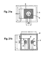
- Fig. 21A is a plan view of the resonator device prior to the attachment of the cavity lid 2.
- Fig. 11B is a center longitudinal cross section of the resonator device having the cavity lid 2 attached thereto.
- the conductor rod 4 is formed integrally with the cavity body 1.
- the top of the conductor rod 4 has a predetermined space from the inner surface of the cavity lid 2.
- the dielectric core 3 is fixed at a predetermined height in the cavity by means of screws 7 and nuts 11.
- the conductor rod 4 may be formed separately from the cavity body 1 and fixed to the cavity body 1.
- Figs. 22A and 22B show an example of the electromagnetic field distribution in the TE mode of this resonator device.
- Fig. 22A is a plan view of the resonator device.
- Fig. 22B is a front view thereof.
- the solid line arrows indicate the electric field vector
- the broken line arrows indicate the magnetic field vector.
- the electric field vector forms a loop in the in-plane direction of the dielectric core.
- Magnetic field loops are distributed perpendicularly to the electric field direction, in a toroidal form.
- the dielectric core has a square sheet shape, a circular cylindrical coordinate system is employed as the representation of a mode.
- the numbers of waves in the respective magnetic field intensity distributions are represented by the sequence of TM ⁇ rh, in which h represents the number of waves in the propagation direction, ⁇ represents the number of waves in the in-plane turning-around direction in a plane perpendicular to the propagation direction, and r represents the number of waves in the in-plane radiation (radial) direction in a plane perpendicular to the propagation direction.
- the mode in this embodiment is represented as TMO1 ⁇ mode.
- the dielectric core 3 has neither a disk shape nor a columnar shape.
- the mode is named a quasi-TE mode.
- the quasi-TEM mode as a resonance mode is generated, caused by the conductor rod 4 and the cavity, as well as in the above-described embodiments.
- Figs. 23A and 23B show an example of the structure inside of another cavity.
- Fig. 23A is a plan view of the resonator device prior to the attachment of the cavity lid 2.
- Fig. 23B is a center cross section thereof.
- a step portion for supporting the bottom of the dielectric core 3 is provided inside of the cavity body 1.
- the dielectric core 3 is fixed to the step portion by screwing screws 7 through spacers 6 having a low dielectric constant, respectively. With this structure, the fixing strength (rigidity) of the dielectric core 3 can be enhanced.
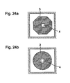
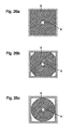
- Figs. 24A, 24B to 26A, 26B, and 26C are examples of a resonator device according to an twelfth embodiment of the present invention, in which the shapes and attachment positions of the dielectric core 3 are different. These figures are plan views of the resonator device as viewed in the axial direction of the conductor rod 4, respectively.
- the dielectric core 3 has an octagonal sheet shape which is similar to a square sheet shape dielectric plate having the four corners thereof cut off.
- the conductor rod 4 has a prism shape, and the hole of the dielectric core 3 has a square in section. Thereby the dielectric core 3 can be located with respect to the axis of the dielectric core 3.
- Fig. 24B shows an example of the resonator including the dielectric core 3 having a disk shape.
- a resonator can be obtained in which generation of spurious modes excluding the employed TE01 ⁇ mode are suppressed.
- the inner wall of the cavity may be cylindrical correspondingly to the shape of the dielectric core 3.
- Fig. 25A and 25B show examples of the resonator device in which the dielectric core 3 is bonded to two adjacent faces of the cavity.
- Figs. 26a, 26B, and 26C shows the examples in which the dielectric core 3 is bonded to or is brought into contact with all of the inner walls of the cavity, respectively.
- the resonance frequency in the above-described quasi-TM mode, caused by the cavity and the dielectric core 3, and that of the above-described quasi-TEM, caused by the cavity and the conductive rod are set at substantially the same value to couple both of the modes.
- the question is that in general, the temperature characteristics (characteristics of resonance frequency change versus temperature change) of these modes are considerably different from each other.
- the size of the cavity is one of the factors by which the resonance frequency is determined. That is, when the cavity is distorted, due to the change of temperature, the resonance frequencies of the two modes are changed.
- a resonator device having a good temperature characteristic is formed by use of a metallic material such as aluminum or the like which is inexpensive, and can be integrally molded.
- the resonance frequency in the quasi-TM mode considerably depends on the dielectric constant of the dielectric core 3.
- the resonance frequency in the quasi-TEM mode hardly depends on the dielectric constant of the dielectric core 3.
- the resonance frequencies in the quasi-TM and quasi-TEM modes are changed.
- the change of the resonance frequency with temperature has a negative coefficient.
- a dielectric material having such a dielectric constant as presents a negative temperature coefficient is employed for the dielectric core 3.
- the dielectric constant can be determined so as to stabilize the temperature characteristic of the resonance frequency in the quasi-TM mode, as described later.
- Fig. 32 shows the results.
- the cavity body 1 was formed from aluminum
- the conductor rod 4 was formed from any one of four types of material, namely, Invar, iron, copper, or aluminum.
- the length of the conductor rod 4 doesn't substantially change, even if the temperature is varied.
- the gap between the top of the conductor rod 4 and the cavity lid 2 is increased, so that the static capacitance, produced in the gap, is decreased.
- the resonance frequency in the quasi-TEM mode is considerably changed to increase.
- the conductor rod 4 is made of aluminum as well as the cavity body 1, the conductor rod 4 expands or shrinks together with the cavity, caused by changes in temperature, so that the gap between the top of the conductor rod 4 and the cavity lid 2 is not significantly varied.
- the conductor rod 4 is elongated with the rise of temperature, resulting in changing the resonance frequency in the quasi-TEM mode to decrease.
- the resonance frequency in the quasi-TEM mode is changed with temperature, correspondingly to the respective linear expansion coefficients of the materials.
- the resonance frequency in the quasi-TM mode is substantially constant, irrespective of materials for the conductor rod 4, and the expansion and shrinkage thereof. Accordingly, the temperature characteristic of the quasi-TEM mode can be determined, independently of the characteristic of the quasi-TM mode, by selecting a metallic material having such a linear expansion coefficient that the change of the resonance frequency in the quasi-TEM mode with temperature becomes substantially constant. In the example of Fig. 32 , the resonance frequency in the quasi-TEM mode can be stabilized for temperature change by using iron as material for the conductor rod 4.
- Figs. 33A, 33B, and 33C show the procedures for controlling the temperature characteristics of the resonance frequencies in the two modes, that is, the quasi-TM and quasi-TEM modes.
- Fig. 33A shows the temperature characteristics. As described above, the resonance frequency in the quasi-TM is decreased, due to the enlargement of the space in the cavity caused by a rise in temperature.
- the change amount of the resonance frequency, caused by changing the dielectric constant of the dielectric core 3 is determined.
- the temperature characteristic of the dielectric constant of the dielectric core 3 is determined in such a manner that the change amount of the resonance frequency in the quasi-TM mode with temperature, determined in Step 1, is made zero.
- selected is such a dielectric material that the temperature coefficient of the dielectric constant ⁇ r of the dielectric core 3 has a predetermined negative value, and the resonance frequency in the quasi-TM mode for changes in temperature becomes constant.
- Fig. 33B shows the temperature characteristic.
- the resonance frequency in the quasi-TM mode is changed with the dielectric constant of the dielectric core 3, as shown in Table 1.
- the change amount can be absorbed in the following step 3.
- the resonance frequency in the quasi-TEM mode is determined eventually by the linear expansion coefficient of the conductor rod 4.
- determined is such a linear expansion coefficient of the conductor rod 4 that the resonance frequency in the quasi-TEM mode becomes substantially constant.
- material for the conductor rod 4 selected is a material having a linear expansion coefficient at which the resonance frequency in the quasi-TEM mode becomes substantially constant for changes in temperature.
- Fig. 33C shows the temperature characteristic.
- the temperature compensation of the quasi-TEM mode is carried out. Succeedingly, the temperature compensation of the quasi-TEM mode is conducted. However, first, the temperature compensation of the quasi-TEM mode may be made, followed by that of the quasi-TM mode may be carried out, since the change of the resonance frequency in the quasi-TEM mode with temperature, based on the change of the dielectric constant of the dielectric core 3, is small.
- Fig. 34A is a plan view of the resonator device prior to the attachment of the cavity lid 2.
- Fig. 34B is a center longitudinal cross section of the resonator device having the cavity lid 2 attached thereto.
- the resonator device differs from that of the first embodiment in that the cavity lid 2 is provided with a frequency adjustment screw 14 for adjusting the resonance frequency in the quasi-TEM mode.
- the static capacitance produced between the screw 14 and the top of the conductor rod 4 is controlled by adjusting the projection degree of the frequency adjustment screw 14 projected into the cavity body 1.
- the resonance frequency in the quasi-TEM mode is controlled by the adjustment of this static capacitance.
- the cavity body 1 is produced by molding aluminum, and forming an Ag plating film on the outer surface of the aluminum molded product.
- the conductor rod 4 a round rod made of iron is used, and the frequency adjustment screw 14 is formed from brass.
- the temperature characteristic of the quasi-TEM mode is changed, depending on the projection degrees of the conductor rod 4 and the frequency adjustment screw 14 and the linear expansion coefficients of them.
- both of the conductor rod 4 and the frequency adjustment screw 14 as a whole function as a center conductor in the quasi-TEM mode.
- the combined linear expansion coefficient is determined by the linear expansion coefficients of the conductor rod 4 and the frequency adjustment screw 14, and the lengths of parts of both of them elongating in the cavity. Accordingly, for design of the resonator device, materials for the conductor rod 4 and the frequency adjustment screw 14 and the lengths thereof are determined so that the change of the resonance frequency in the quasi-TEM mode with temperature can be stabilized.
- the material for the conductor rod in the preferable form of the present invention means the material for each of the conductor rod 4 and the frequency adjustment screw 14, shown in Fig. 34A and 34B .
- the material is selected of which the temperature coefficient ⁇ f of the dielectric constant is - 15(ppm/°C) so that the resonance frequency in the quasi-TM mode is substantially constant for changes in temperature.
- a dielectric ceramic of (Zr, Sn) TiO 2 may be employed.
- a filter according to a fourteenth embodiment of the present invention will be described with reference to Fig. 27 .
- the cavities are shown by alternate long and two short dash lines.
- the tops of conductor rods 4a and 4b are spaced from the inner walls of the cavities.
- this device functions as a resonator operating in a quasi-TEM mode produced by the conductor rod 4a and the cavity surrounding the conductor rod 4a, and moreover, functions as a resonator operating in a quasi-TM mode produced by a dielectric core 3a and the cavity surrounding the conductor rod 3a.
- this device functions as a resonator operating in a quasi-TEM mode produced by the conductor rod 4b and the cavity surrounding the conductor rod 4b, and moreover, functions as a resonator operating in a quasi-TM mode produced by a dielectric core 3b and the cavity surrounding the dielectric core 3b.
- Coaxial connectors 8a and 8b are provided, and the center conductors of the connectors 8a and 8b and the inner surfaces of the cavity are connected through coupling loop 9a and 9b, respectively.
- the coupling loops 9a and 9b are arranged in such a manner that the loop planes thereof link with magnetic fields in the above-described quasi-TM mode are linked together, and don't substantially link with magnetic fields in the quasi-TEM mode, respectively.
- these coupling loops 9a and 9b are coupled with the magnetic fields in the above-described quasi-TM mode.
- Coupling adjustment holes ha and hb are provided to couple the quasi-TM and quasi-TEM modes to each other.
- a window is formed in the wall between the two adjacent cavities.
- a coupling loop 10 is disposed so as to extend through the window. The loop plane of the coupling loop 10 is directed in such a manner that the magnetic fields in the quasi-TM mode don't link with each other, and the magnetic fields in the quasi-TEM mode link with each other.
- the coupling loop 10 links with the magnetic fields in the quasi-TEM mode, produced in the two cavities.
- this device functions as a filter comprising four stage resonators, having a band-pass characteristic.
- Fig. 28A is a perspective view of the filter
- Fig. 28B is a plan view thereof.
- the cavity is shown by an alternate long and two short dash line.
- the dielectric core 3 and the conductor rod 4 inserted in and through a hole formed in the center of the conductor rod 4 are provided.
- the resonator in the quasi-TEM mode caused by the cavity and the conductor rod 4 and the resonator in the quasi-TE mode caused by the dielectric core 3 are multiplexed.
- Two coupling loops 10a and 10b are provided in the cavity, and moreover, and are connected through a cable 12 having an electrical length of one-quarter wavelength.
- the coupling loop 10a is directed in such a manner that it links with the magnetic field in the quasi-TEM mode, and doesn't link with the magnetic field in the quasi-TE mode.
- the coupling loop 10b is directed in such a manner that it links with the magnetic field in the quasi-TE mode, and doesn't link with magnetic field in the quasi-TEM mode.
- the resonator in the quasi-TEM mode and the resonator in the quasi-TE mode are coupled through the cable 12 having a one-quarter wavelength.
- this filter is used as a band-elimination filter, another coupling loop for coupling the magnetic fields in the quasi-TEM and quasi-TE modes is provided.
- the filter comprising the two stage resonators is connected between a transmission line and the ground.
- Fig. 29 is a graph showing the transmission characteristic of the above-described filter. As seen in the graph, a band-elimination filter characteristic can be obtained, in which the resonance frequencies of the two stage resonators are attenuated.
- Fig. 30 shows an example of the configuration of a transmission reception sharing device.
- the transmission filter and the reception filter are band-pass filters each having the same configuration as the above-described dielectric filter.
- the transmission filter allows a transmission frequency signal to pass, and the reception filter allows a reception frequency signal to pass.
- the position at which the output port of the transmission filter and the input port of the reception filter are connected to each other is set in such a manner that the electrical length of from the connection point to the equivalent short-circuiting plane of the final stage resonator of the transmission filter is odd-number times the one-quarter wavelength at the frequency of a transmission signal, and also, the electrical length of from the connection point to the equivalent short-circuiting plane of the initial stage resonator of the reception filter is odd-number times the one-quarter wavelength at the frequency of a reception signal. This causes the transmission and reception signals to be securely branched.
- a diplexer and a multiplexer can be formed by providing plural dielectric filters between the common port and the individual ports, as described above.
- Fig. 31 is a block diagram showing the configuration of a communication device including the above-described transmission reception sharing device (duplexer). As seen in Fig. 31 , a transmission circuit is connected to the input port of the transmission filer, a reception circuit is connected to the output port of the reception filter, and an antenna is connected to the input-output port of the duplexer. Thus, a high frequency section of the communication device is formed.
- the communication device can be reduced in size.
- the resonators can be multiplexed in one cavity.
- the whole configuration of a resonator device having a predetermined number of stages can be reduced in size.
- the dielectric core can be disposed at an optional position, e.g., in the center of the cavity.
- the capacitance component which determines the resonance frequency in the resonance mode, caused by the cavity and the dielectric core can be increased. Accordingly, the resonator can be miniaturized by reducing the size of the cavity.
- the capacitance component which determines the resonance frequency in the resonance mode, caused by the cavity and the dielectric core, can be decreased. Accordingly, the size of the cavity can be increased to some degree, so that the Q value of the resonator is enhanced.
- Three resonators can be formed in one cavity. Further miniaturization is possible.
- the temperature characteristics in the resonance modes caused by the cavity and the dielectric core and by the conductor rod and the cavity can be easily stabilized.
- the filter, the composite filter device, and the duplexer each comprising multi-stage resonators can be easily formed.
- a communication device having a small whole-size, a low loss, and a high gain can be easily formed by use of the resonators which are small in size and have a high Q value.
Landscapes
- Physics & Mathematics (AREA)
- Electromagnetism (AREA)
- Control Of Motors That Do Not Use Commutators (AREA)
Claims (9)
- Ein Resonatorbauelement, das einen leitfähigen Stab (4) umfasst, der in einem leitfähigen Hohlraum (1) vorgesehen ist, wobei zumindest ein Ende des leitfähigen Stabs (4) elektrisch mit dem leitfähigen Hohlraum (1) verbunden ist, und einen dielektrischen Kern (3), der in dem leitfähigen Hohlraum (1) vorgesehen ist, wobei die Resonanzfrequenz in einer ersten Resonanzmode, die durch den leitfähigen Hohlraum (1) und den leitfähigen Stab (4) bewirkt wird, und die Resonanzfrequenz in einer zweiten Resonanzmode, die durch den leitfähigen Hohlraum (1) und den dielektrischen Kern (3) bewirkt wird, eingestellt sind, um im Wesentlichen gleich zueinander zu sein, um beide Moden zu koppeln;
wobei die erste Resonanzmode, die durch den leitfähigen Hohlraum (1) und den leitfähigen Stab (4) bewirkt wird, eine Quasi-TEM-Mode ist, die zweite Resonanzmode, die durch den leitfähigen Hohlraum (1) und den dielektrischen Kern (3) bewirkt wird, eine Quasi-TEM-Mode ist, und die beiden Resonanzmoden zu Duplex-Moden gemacht werden;
wobei in der Mitte des dielektrischen Kerns (3) ein Loch gebildet ist, und der leitfähige Stab (4) in und durch das Loch eingefügt wird; und
wobei ein Zwischenraum zwischen dem Abschnitt des leitfähigen Stabs (4), der sich durch das Loch in dem leitfähigen Kern (3) erstreckt, und dem dielektrischen Kern (3) vorgesehen ist. - Ein Resonatorbauelement gemäß Anspruch 1, bei dem der dielektrische Kern (3) mit der Innenoberfläche des leitfähigen Hohlraums (1) verbunden ist.
- Ein Resonatorbauelement gemäß einem der Ansprüche 1 und 2, bei dem der dielektrische Kern auf einem Ständer (5) in dem leitfähigen Hohlraum (1) getragen wird, und der dielektrische Kern (3) von der Innenoberfläche des leitfähigen Hohlraums (1) beabstandet ist.
- Ein Resonatorbauelement gemäß einem der Ansprüche 1 bis 3, bei dem die erste Resonanzmode, die durch den leitfähigen Hohlraum (1) und den leitfähigen Stab (4) bewirkt wird, eine Quasi-TEM-Mode ist, die zweite Resonanzmode, die durch den leitfähigen Hohlraum (1) und den dielektrischen Kern (3) bewirkt wird, eine Quasi-TEM-Mode ist, und die beiden Resonanzmoden zu Duplex-Moden gemacht werden.
- Ein Resonatorbauelement gemäß einem der Ansprüche 1 bis 3, bei dem die erste Resonanzmode, die durch den leitfähigen Hohlraum (1) und den leitfähigen Stab (4) bewirkt wird, eine Quasi-TEM-Mode ist, die zweite Resonanzmode, die durch den leitfähigen Hohlraum (1) und den dielektrischen Kern (3) bewirkt wird, eine Quasi-TEM-Mode ist, und die Moden insgesamt zu Triplex-Moden gemacht werden.
- Ein Filter, das ein Resonatorbauelement gemäß einem der Ansprüche 1 bis 5 umfasst, wobei das Filter ferner einen Eingabe-Ausgabe-Leiter (9a, 9b; 10a, 10b) umfasst, zum Koppeln mit einer vorbestimmten Mode der obigen Resonanzmoden und zum Ausführen einer Eingabe-Ausgabe eines Signals, wobei der Eingabe-Ausgabe-Leiter (9a, 9b; 10a, 10b) in dem Resonatorbauelement vorgesehen ist.
- Ein zusammengesetztes Filterbauelement, das mehrere Sätze von Filtern gemäß Anspruch 6 umfasst.
- Ein Duplexer, der zwei Sätze der Filter gemäß Anspruch 6 umfasst, wobei das Eingangstor des ersten Filters ein Eingangstor für ein Sendesignal ist, das Ausgangstor des zweiten Filters ein Ausgangstor für ein Empfangssignal ist, das Eingangs-Ausgangs-Tor, das durch das erste und das zweite Filter gemeinschaftlich verwendet wird, ein Antennentor ist.
- Ein Kommunikationsbauelement, das das Filter gemäß Anspruch 6, das zusammengesetzte Filterbauelement gemäß Anspruch 7 oder den Duplexer gemäß Anspruch 8 umfasst.
Applications Claiming Priority (4)
| Application Number | Priority Date | Filing Date | Title |
|---|---|---|---|
| JP28303799 | 1999-10-04 | ||
| JP28303799 | 1999-10-04 | ||
| JP2000165335 | 2000-06-02 | ||
| JP2000165335A JP3506104B2 (ja) | 1999-10-04 | 2000-06-02 | 共振器装置、フィルタ、複合フィルタ装置、デュプレクサおよび通信装置 |
Publications (3)
| Publication Number | Publication Date |
|---|---|
| EP1091441A2 EP1091441A2 (de) | 2001-04-11 |
| EP1091441A3 EP1091441A3 (de) | 2002-04-10 |
| EP1091441B1 true EP1091441B1 (de) | 2009-02-25 |
Family
ID=26554872
Family Applications (1)
| Application Number | Title | Priority Date | Filing Date |
|---|---|---|---|
| EP00121698A Expired - Lifetime EP1091441B1 (de) | 1999-10-04 | 2000-10-04 | Resonatorvorrichtung, Filter, zusammengestelltes Filter, Duplexer und Kommunikationsgerät |
Country Status (4)
| Country | Link |
|---|---|
| US (1) | US6549092B1 (de) |
| EP (1) | EP1091441B1 (de) |
| JP (1) | JP3506104B2 (de) |
| DE (1) | DE60041619D1 (de) |
Families Citing this family (32)
| Publication number | Priority date | Publication date | Assignee | Title |
|---|---|---|---|---|
| JP3506124B2 (ja) * | 2001-02-28 | 2004-03-15 | 株式会社村田製作所 | フィルタ装置、デュプレクサおよび基地局用通信装置 |
| JP3633520B2 (ja) * | 2001-04-04 | 2005-03-30 | 株式会社村田製作所 | 共振器装置、フィルタ、デュプレクサおよび通信装置 |
| JP3596505B2 (ja) | 2001-09-27 | 2004-12-02 | 株式会社村田製作所 | 誘電体共振器、フィルタ、デュプレクサおよび通信装置 |
| JP2004186712A (ja) * | 2001-12-13 | 2004-07-02 | Murata Mfg Co Ltd | 誘電体共振素子、誘電体共振器、フィルタ、発振器装置、および通信装置 |
| US7405815B1 (en) * | 2003-11-04 | 2008-07-29 | The Boeing Company | Systems and methods for characterizing laser beam quality |
| US7078990B1 (en) * | 2004-05-14 | 2006-07-18 | Lockheed Martin Corporation | RF cavity resonator with low passive inter-modulation tuning element |
| WO2006026826A1 (en) * | 2004-09-09 | 2006-03-16 | Filtronic Pty Ltd | Multiband filter |
| WO2006075439A1 (ja) * | 2005-01-11 | 2006-07-20 | Murata Manufacturing Co., Ltd. | チューナブルフィルタ、デュプレクサおよび通信機装置 |
| JP4795130B2 (ja) * | 2006-01-25 | 2011-10-19 | スタンレー電気株式会社 | 光源装置 |
| EP1962370A1 (de) * | 2007-02-21 | 2008-08-27 | Matsushita Electric Industrial Co., Ltd. | Dielektrischer multimoder Resonator |
| US8723722B2 (en) * | 2008-08-28 | 2014-05-13 | Alliant Techsystems Inc. | Composites for antennas and other applications |
| JP5310022B2 (ja) * | 2009-01-22 | 2013-10-09 | 日本電気株式会社 | マイクロ波帯域制限フィルタ、その溶接方法、及び、マイクロ波帯域制限フィルタを備えた人工衛星 |
| US8410792B2 (en) | 2009-03-02 | 2013-04-02 | Forschungszentrum Juelich Gmbh | Resonator arrangement and method for analyzing a sample using the resonator arrangement |
| DE102009011069B3 (de) * | 2009-03-02 | 2010-07-15 | Forschungszentrum Jülich GmbH | Resonatoranordnung und Verfahren zur Untersuchung einer Probe mit der Resonatoranordnung |
| CN103155273B (zh) * | 2010-09-29 | 2014-12-24 | 京瓷株式会社 | 同轴谐振器及利用其的电介质滤波器、无线通信模块及无线通信设备 |
| US9385409B2 (en) * | 2011-09-30 | 2016-07-05 | Toshio Ishizaki | Multi-mode resonator/filter comprised of first and second columnar central conductors disposed within a cylindrical exterior conductor |
| KR101414093B1 (ko) * | 2012-10-19 | 2014-07-01 | 주식회사 이너트론 | 복합 재질의 공진기 및 이를 구비하는 통신 장치 |
| JP5989890B2 (ja) * | 2013-02-26 | 2016-09-07 | 京セラ株式会社 | 誘電体フィルタ,デュプレクサおよび通信装置 |
| CN105408973B (zh) * | 2013-08-08 | 2017-10-03 | 株式会社Ihi | 非接触供电装置的制造方法及共振器 |
| WO2016023070A1 (en) * | 2014-08-12 | 2016-02-18 | The University Of Western Australia | Microwave frequency magnetic field manipulation systems and methods and associated application instruments, apparatus and system |
| DE102015005613B4 (de) | 2015-04-30 | 2017-04-06 | Kathrein-Werke Kg | Multiplexfilter mit dielektrischen Substraten zur Übertragung von TM-Moden in transversaler Richtung |
| DE102015005523B4 (de) | 2015-04-30 | 2018-03-29 | Kathrein-Werke Kg | Hochfrequenzfilter mit dielektrischen Substraten zur Übertragung von TM-Moden in transversaler Richtung |
| CN109075422B (zh) | 2016-04-26 | 2020-02-21 | 华为技术有限公司 | 介质谐振器及应用其的介质滤波器、收发信机及基站 |
| WO2018119825A1 (zh) * | 2016-12-29 | 2018-07-05 | 深圳市大富科技股份有限公司 | 一种tem模滤波器及通信设备 |
| CN108258371B (zh) * | 2018-02-05 | 2020-02-18 | 华南理工大学 | 一种基于电容加载与开槽耦合的介质三模滤波器 |
| GB201906093D0 (en) * | 2019-05-01 | 2019-06-12 | Radio Design Ltd | Multi-mode resonator apparatus and method of use thereof |
| CN209929461U (zh) | 2019-06-28 | 2020-01-10 | 瑞典爱立信有限公司 | 谐振器装置和滤波器装置 |
| CN111900524B (zh) * | 2020-08-07 | 2021-09-03 | 物广系统有限公司 | 一种谐振单元和介质滤波器 |
| CN112186323A (zh) * | 2020-09-04 | 2021-01-05 | 广州司南天线设计研究所有限公司 | 微波谐振器和滤波器 |
| CN112271423A (zh) * | 2020-11-13 | 2021-01-26 | 深圳顺络电子股份有限公司 | 一种谐振器结构、滤波器、双工器、多工器、通讯基站 |
| CN113540716A (zh) * | 2021-08-30 | 2021-10-22 | 苏州波发特电子科技有限公司 | 一种新型滤波器 |
| CN120049166A (zh) * | 2023-11-24 | 2025-05-27 | 上海华为技术有限公司 | 一种谐振器、滤波器及电子设备 |
Family Cites Families (5)
| Publication number | Priority date | Publication date | Assignee | Title |
|---|---|---|---|---|
| JPS5622323Y2 (de) * | 1976-05-24 | 1981-05-26 | ||
| JPS60107902A (ja) * | 1983-11-16 | 1985-06-13 | Matsushita Electric Ind Co Ltd | 同軸型共振器 |
| JPS6179301A (ja) * | 1984-09-27 | 1986-04-22 | Nec Corp | 誘電体共振器帯域通過ろ波器 |
| JPS61245606A (ja) * | 1985-04-23 | 1986-10-31 | Alps Electric Co Ltd | マイクロ波発振器 |
| DE4018219A1 (de) * | 1990-06-07 | 1991-12-19 | Ant Nachrichtentech | Mikrowellenfilter |
-
2000
- 2000-06-02 JP JP2000165335A patent/JP3506104B2/ja not_active Expired - Fee Related
- 2000-10-04 DE DE60041619T patent/DE60041619D1/de not_active Expired - Lifetime
- 2000-10-04 EP EP00121698A patent/EP1091441B1/de not_active Expired - Lifetime
- 2000-10-04 US US09/679,176 patent/US6549092B1/en not_active Expired - Lifetime
Also Published As
| Publication number | Publication date |
|---|---|
| US6549092B1 (en) | 2003-04-15 |
| DE60041619D1 (de) | 2009-04-09 |
| JP3506104B2 (ja) | 2004-03-15 |
| EP1091441A2 (de) | 2001-04-11 |
| JP2001177313A (ja) | 2001-06-29 |
| EP1091441A3 (de) | 2002-04-10 |
Similar Documents
| Publication | Publication Date | Title |
|---|---|---|
| EP1091441B1 (de) | Resonatorvorrichtung, Filter, zusammengestelltes Filter, Duplexer und Kommunikationsgerät | |
| Chen et al. | A dual-mode monoblock dielectric bandpass filter using dissimilar fundamental modes | |
| US4410868A (en) | Dielectric filter | |
| EP1014473B1 (de) | Multimodale dielektrische resonanzvorrichtungen, dielektrisches filter,zusammengestelltes dielektrisches filter, synthetisierer, verteiler und kommunikationsgerät | |
| EP1014474B1 (de) | Multimodale dielektrische resonanzvorrichtung, dielktrisches filter, synthesierer, verteiler und kommunikationsgerät | |
| JP2001189612A (ja) | 共振器、共振素子、共振器装置、フィルタ、デュプレクサおよび通信装置 | |
| JP2000295009A (ja) | 一般応答デュアルモード、誘電体共振器にロードされる空洞共振器フィルタ | |
| US5804534A (en) | High performance dual mode microwave filter with cavity and conducting or superconducting loading element | |
| Xiang et al. | Compact waveguide filters using novel resonant coupling structures | |
| Bakr et al. | Miniature triple-mode dielectric resonator filters | |
| EP1732158A1 (de) | Mikrowellenfilter mit einem stirnwandgekoppelten Koaxialresonator | |
| WO2009067056A1 (en) | A filter for use in a wireless communications network | |
| Zhao et al. | Monolithic multiband coaxial resonator-based bandpass filter using stereolithography apparatus (SLA) manufacturing | |
| US5495216A (en) | Apparatus for providing desired coupling in dual-mode dielectric resonator filters | |
| Rao et al. | Analysis of the compact graded dumbbell coaxial resonator with its filter design applications | |
| US6756865B2 (en) | Resonator device, filter, duplexer, and communication apparatus using the same | |
| JPH11308009A (ja) | シングルモード及びデュアルモードヘリックス装着空洞フィルタ | |
| EP1079457B1 (de) | Dielektrische Resonanzvorrichtung, dielektrisches Filter, zusammengestellte dielektrische Filtervorrichtung, dielektrischer Duplexer und Kommunikationsgerät | |
| CN119481654B (zh) | 一种双模谐振器、双模滤波器及多工器 | |
| Zhao et al. | Monolithically-integrated 3D printed bandpass filters using highly-miniaturized dome-shaped resonators | |
| Mohanan et al. | Applications of Dielectric Resonators | |
| Matsumoto et al. | A miniaturized dielectric monoblock band-pass filter for 800 MHz band cordless telephone system | |
| JP2004349981A (ja) | 共振器装置、フィルタ、複合フィルタ装置および通信装置 | |
| JP2001085908A (ja) | 多重モード共振器装置、フィルタ、複合フィルタ装置、デュプレクサおよび通信装置 | |
| Chen et al. | Metal-dielectric coaxial dual-mode resonator for compact inline bandpass filters |
Legal Events
| Date | Code | Title | Description |
|---|---|---|---|
| PUAI | Public reference made under article 153(3) epc to a published international application that has entered the european phase |
Free format text: ORIGINAL CODE: 0009012 |
|
| 17P | Request for examination filed |
Effective date: 20001004 |
|
| AK | Designated contracting states |
Kind code of ref document: A2 Designated state(s): AT BE CH CY DE DK ES FI FR GB GR IE IT LI LU MC NL PT SE Kind code of ref document: A2 Designated state(s): DE FI FR GB SE |
|
| AX | Request for extension of the european patent |
Free format text: AL;LT;LV;MK;RO;SI |
|
| PUAL | Search report despatched |
Free format text: ORIGINAL CODE: 0009013 |
|
| AK | Designated contracting states |
Kind code of ref document: A3 Designated state(s): AT BE CH CY DE DK ES FI FR GB GR IE IT LI LU MC NL PT SE |
|
| AX | Request for extension of the european patent |
Free format text: AL;LT;LV;MK;RO;SI |
|
| AKX | Designation fees paid |
Free format text: DE FI FR GB SE |
|
| RAP1 | Party data changed (applicant data changed or rights of an application transferred) |
Owner name: MURATA MANUFACTURING CO., LTD. |
|
| 17Q | First examination report despatched |
Effective date: 20071213 |
|
| GRAP | Despatch of communication of intention to grant a patent |
Free format text: ORIGINAL CODE: EPIDOSNIGR1 |
|
| GRAS | Grant fee paid |
Free format text: ORIGINAL CODE: EPIDOSNIGR3 |
|
| GRAA | (expected) grant |
Free format text: ORIGINAL CODE: 0009210 |
|
| AK | Designated contracting states |
Kind code of ref document: B1 Designated state(s): DE FI FR GB SE |
|
| REG | Reference to a national code |
Ref country code: GB Ref legal event code: FG4D |
|
| REF | Corresponds to: |
Ref document number: 60041619 Country of ref document: DE Date of ref document: 20090409 Kind code of ref document: P |
|
| PG25 | Lapsed in a contracting state [announced via postgrant information from national office to epo] |
Ref country code: FI Free format text: LAPSE BECAUSE OF FAILURE TO SUBMIT A TRANSLATION OF THE DESCRIPTION OR TO PAY THE FEE WITHIN THE PRESCRIBED TIME-LIMIT Effective date: 20090225 |
|
| PG25 | Lapsed in a contracting state [announced via postgrant information from national office to epo] |
Ref country code: SE Free format text: LAPSE BECAUSE OF FAILURE TO SUBMIT A TRANSLATION OF THE DESCRIPTION OR TO PAY THE FEE WITHIN THE PRESCRIBED TIME-LIMIT Effective date: 20090525 |
|
| PLBE | No opposition filed within time limit |
Free format text: ORIGINAL CODE: 0009261 |
|
| STAA | Information on the status of an ep patent application or granted ep patent |
Free format text: STATUS: NO OPPOSITION FILED WITHIN TIME LIMIT |
|
| 26N | No opposition filed |
Effective date: 20091126 |
|
| REG | Reference to a national code |
Ref country code: FR Ref legal event code: ST Effective date: 20100630 |
|
| PG25 | Lapsed in a contracting state [announced via postgrant information from national office to epo] |
Ref country code: FR Free format text: LAPSE BECAUSE OF NON-PAYMENT OF DUE FEES Effective date: 20091102 |
|
| PG25 | Lapsed in a contracting state [announced via postgrant information from national office to epo] |
Ref country code: GB Free format text: LAPSE BECAUSE OF NON-PAYMENT OF DUE FEES Effective date: 20091004 |
|
| PGFP | Annual fee paid to national office [announced via postgrant information from national office to epo] |
Ref country code: DE Payment date: 20181019 Year of fee payment: 19 |
|
| REG | Reference to a national code |
Ref country code: DE Ref legal event code: R119 Ref document number: 60041619 Country of ref document: DE |
|
| PG25 | Lapsed in a contracting state [announced via postgrant information from national office to epo] |
Ref country code: DE Free format text: LAPSE BECAUSE OF NON-PAYMENT OF DUE FEES Effective date: 20200501 |