EP1091464B1 - Support de montage d'appareils dans une goulotte - Google Patents
Support de montage d'appareils dans une goulotte Download PDFInfo
- Publication number
- EP1091464B1 EP1091464B1 EP99307798A EP99307798A EP1091464B1 EP 1091464 B1 EP1091464 B1 EP 1091464B1 EP 99307798 A EP99307798 A EP 99307798A EP 99307798 A EP99307798 A EP 99307798A EP 1091464 B1 EP1091464 B1 EP 1091464B1
- Authority
- EP
- European Patent Office
- Prior art keywords
- channel
- shaped member
- trunking
- cover means
- accessory mounting
- Prior art date
- Legal status (The legal status is an assumption and is not a legal conclusion. Google has not performed a legal analysis and makes no representation as to the accuracy of the status listed.)
- Expired - Lifetime
Links
- 238000001125 extrusion Methods 0.000 claims 1
- 238000000465 moulding Methods 0.000 claims 1
- 238000009740 moulding (composite fabrication) Methods 0.000 claims 1
- 239000000463 material Substances 0.000 description 5
- 239000004411 aluminium Substances 0.000 description 4
- 229910052782 aluminium Inorganic materials 0.000 description 4
- XAGFODPZIPBFFR-UHFFFAOYSA-N aluminium Chemical compound [Al] XAGFODPZIPBFFR-UHFFFAOYSA-N 0.000 description 4
- 239000004020 conductor Substances 0.000 description 4
- 229910052751 metal Inorganic materials 0.000 description 4
- 239000002184 metal Substances 0.000 description 4
- 230000003287 optical effect Effects 0.000 description 2
- 229920001169 thermoplastic Polymers 0.000 description 2
- 239000012815 thermoplastic material Substances 0.000 description 2
- 239000004416 thermosoftening plastic Substances 0.000 description 2
- 230000015572 biosynthetic process Effects 0.000 description 1
- 238000004519 manufacturing process Methods 0.000 description 1
- 238000000034 method Methods 0.000 description 1
- 230000003313 weakening effect Effects 0.000 description 1
Images

Classifications
-
- H—ELECTRICITY
- H02—GENERATION; CONVERSION OR DISTRIBUTION OF ELECTRIC POWER
- H02G—INSTALLATION OF ELECTRIC CABLES OR LINES, OR OF COMBINED OPTICAL AND ELECTRIC CABLES OR LINES
- H02G3/00—Installations of electric cables or lines or protective tubing therefor in or on buildings, equivalent structures or vehicles
- H02G3/02—Details
- H02G3/08—Distribution boxes; Connection or junction boxes
- H02G3/12—Distribution boxes; Connection or junction boxes for flush mounting
- H02G3/128—Distribution boxes; Connection or junction boxes for flush mounting in plinths, channels, raceways or similar
Definitions
- the present invention provides an accessory mounting for use in trunking, a kit for forming an accessory mounting for use in trunking and a combination of trunking and an accessory mounting.
- Electrical and communications trunking is widely used to provide electrical power and communication services within buildings.
- Such trunking typically comprises a longitudinally extending channel of indefinite length defined by a longitudinally extending floor member and a pair of longitudinally extending wall members projecting from the floor member.
- Various longitudinally extending mounting means are typically provided for supporting within the channel longitudinally electrically extending electrical conductors (commonly called busbars) or electrical or optical communication cables.
- Access to electrical power or communications can be provided at any selected point along the length of the trunking by accessories, such as electrical sockets, communication sockets and the like, which engage with respective conductors or cables.
- accessories typically comprise accessory mountings as part of their design, or are fixed in accessory boxes which provides a rigid support for the accessory and which can be conveniently engaged at any suitable point in the trunking.
- Lid members may be provided to give a flush surface to the trunking between accessories.
- the trunking is typically mounted on walls extending in the horizontal direction, but it may be mounted extended in any suitable direction, including vertically.
- An accessory mounting may be configured to support a plurality of similar or different accessories if necessary, for example double electrical power sockets.
- the present inventors have realised that considerable simplification of the equipment and stores necessary for installing trunking, or of the methods of manufacturing such equipment and stores, can be obtained if the accessory mounting is formed from a kit which includes a longitudinally extending member which can be cut to a suitable length to house one, two or more accessories.
- the present invention provides an accessory mounting for use in trunking of the sort comprising a longitudinally extending channel of indefinite length defined by a longitudinally extending floor member and at least two longitudinally extending wall members projecting from the floor member, the accessory mounting comprising
- the present invention further provides a kit for forming an accessory mounting for use in trunking of the sort comprising a longitudinally extending channel of indefinite length defined by a longitudinally extending floor member and at least two longitudinally extending wall members projecting from the floor member, the kit comprising:
- channel-shaped member is configured to engage with the cover means and the trunking, there need not be any direct engagement between the channel-shaped member and the trunking.
- the channel-shaped member will be of length sufficient to accommodate a defined number of accessories.
- a further embodiment of the present invention provides a combination of an accessory mounting according to the present invention and trunking.
- a further embodiment of the invention provides end wall parts for engaging the first and second ends or a cover part, or both.
- the trunking may of any suitable type. It is suitably made of cast, moulded or extruded material, for example thermoplastic material or metal, particularly uPVC or aluminium.
- the trunking comprises members projecting from the floor member for engaging with cables, conductors, busbars, optical fibres etc.
- the trunking may comprise means defining additional or subsidiary longitudinally extending channels.
- lid means for closing the channel comprises lid means for closing the channel.
- Suitable trunking is described for example in GB-A-2253096 and GB-A-2282278 .
- the channel-shaped member may be supplied in any length.
- the channel-shaped member may be cut to the desired length or it may be provided with weakenings whereby it can be snapped apart into parts of the desired length.
- the desired length will typically correspond to a length large enough to accommodate one, two or more accessories.
- the channel-shaped member as supplied will be long enough to accommodate at least two accessories
- the channel-shaped member preferably comprises a longitudinally extending channel-floor member and at least two longitudinally extending channel-wall members, preferably formed at the extremities of the channel-floor member.
- the channel-shaped member may be suitably made of cast, moulded, formed (ie provided by folding and cutting) or extruded material, for example thermoplastic or metal, particularly uPVC or aluminium. It is particularly preferred that it is formed of extruded material.
- the ends of the channel-shaped member lie at right angles to the longitudinal direction of the channel-shaped member.
- the end wall parts preferably substantially completely close the ends of the channel-shape member.
- the end walls parts are preferably releasably engageable with the ends of the channel-shaped member so that the accessory mounting can be taken apart for re-use.
- the end wall parts comprise an end wall face and rim parts extending generally at right angles to the end wall face, which rim parts are configured to lie, in use, against the walls of the channel-shaped member on the outside or on the inside of the channel. This may define a stiff enough joint for no further connection to be required, but it is preferred that further overlapping sleeve members are provided for overlapping the walls of the channel-shaped member on the opposite side to the rim parts.
- the end wall parts are suitably made of cast or moulded material, for example thermoplastic or metal, particularly uPVC or aluminium.
- the end wall parts may additionally comprise means for engaging the trunking, in particular they may have engaging means for engaging the channel-wall members of the trunking.
- Each of the channel-shaped member and the end wall parts may comprise knock-out portions which can be knocked-out in use to allow access for cables, fibres, etc.
- the channel-shaped member comprises an extruded member. This will make the formation of knock-out portions difficult, so that it is particularly preferred in this embodiment that the end wall parts comprise knock-out portions.
- the cover means is provided for closing the open face of the channel-shaped member.
- the cover means may be of any suitable design. It is suitably made of cast, moulded or extruded material, for example thermoplastic material or metal, particularly uPVC or aluminium. It may engage the channel-shape member or the end wall parts or both of them by any suitable means, for example snap fit or screw connections.
- a kit according to the invention comprises a set of different cover means, including cover means suitable for different numbers of accessories.
- the cover means may comprise openings through which the accessory protrudes, for example a hole for a switch or a space for a three-pin socket.
- the cover means comprises means for engaging with the trunking and, separately, means for engaging the channel-shaped member, whereby the channel-shaped member is fixed in position in the trunking through its engagement with the cover means.
- the means for engaging the trunking and the channel-shaped member may be any suitable means.
- they may comprise snap-fit engaging means.
- each end wall comprises an upwardly directed extension, for projecting above the level of the open face of the channel-shaped member, the cover means comprising an abutment against which the upwardly directed extension of the end wall part abuts, when in position, to prevent movement of the end wall out of engagement with the channel-shaped member in the longitudinal direction of the channel-shaped member.
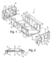
- Figure 1 shows a kit for producing an accessory mounting according to the present invention.
- the kit (1) includes a channel-shaped member (2)comprising a longitudinally extending channel-floor member (3) and longitudinally extending channel-wall members (4) and (5) extending from the extremities of the floor member (3).
- a lip (6) is formed at the ends of wall members (4) and (5) for engagement with trunking (not shown).
- the channel-shaped member (2) is supplied at or is cut to a desired length L which, in this case, is sufficient to accommodate two accessories (not shown).
- the ends (7) and (8) of the channel-shaped member (2) lie in a plane at right angles to the longitudinal direction x of the channel-shaped member (2).
- End wall parts (9) and (10) are provided for closing the ends (7) and (8) of the channel-shaped member.
- Each comprises an end wall face (11) and rim parts (12) extending around three sides of the end wall face (11).
- the end wall parts (9) and (10) lie flush against the ends (7) and (8) of the channel-shaped member with the rim parts (12) overlapping the channel-wall members (4) and (50) and the channel-floor member (3) at the ends thereof.
- overlapping sleeve members (13) are provided on the inside of the end wall parts, to grip the channel-wall members (4) and (5) and the channel-floor member (3).
- Each end wall part (9) and (10) comprises an extension in the form of a lip (21), whose function will be described further below.
- Knock-out portions (14) are providedon the end wall parts (9) and (10) and the channel-shaped member (2), which can be knocked-out to provide access from the inside of the channel-shaped member (2) for cables, conductors etc. in trunking.
- FIG 2 shows a view, partly in cross-section, of a cover means for use in the present invention.
- the cover means (15) comprises cast uPVC. It comprises an outer face (16) profiled to give a smooth, clean exterior appearance. It has an opening 17 through which accessories can project.
- the cover means (15) further comprises means (16), (17) for engaging with channel-wall members of trunking (not shown).
- the cover means (15) further comprises means (18) comprising a notch into which the lip (6) of the channel-shaped member (2) can be snap-fitted during assembly, whereby the channel-shaped member (2) is held in position by the cover means (15). The entire assembly can be fixed into trunking using the means (16) and (17).
- Figure 3 shows a side view, partially in cross-section, of the cover means (15). The position of notch (18) is shown on the right-hand side of the figure.
- the cover means (15) further comprises an edge (19) forming an abutment against which the end wall members (9) or (10) can engage.
- the cover means (15) also comprises a notch (20) for engaging cover members of the trunking (not shown).
- Figure 4 shows a view of the cover (15) in perspective, from the top, showing the longitudinally displaced positions of the means (16) and (17).
- Figure 5 is a cross-sectional view, from the side, of the channel-shaped member (2) engaged with the end wall part (10) through the sleeve members (13).
- a projection in the form of a lip (21) can be seen extending from the end wall part (10) and abutting against abutment (19), thereby preventing longitudinal movement of the end wall part (10) and the channel-shaped member (2).
- the channel-shaped member is engaged by its lip (6) in the notch (18) (not shown).
Landscapes
- Engineering & Computer Science (AREA)
- Architecture (AREA)
- Civil Engineering (AREA)
- Structural Engineering (AREA)
- Details Of Indoor Wiring (AREA)
- Purses, Travelling Bags, Baskets, Or Suitcases (AREA)
- Supporting Of Heads In Record-Carrier Devices (AREA)
Claims (10)
- Support de montage d'accessoires (1) destiné à être utilisé dans une goulotte du type comprenant un canal à extension longitudinale d'une longueur indéfinie, définie par un élément de plancher à extension longitudinale et au moins deux éléments de paroi à extension longitudinale débordant de l'élément de plancher, le support de montage d'accessoires (1) comprenant :(a) un élément en forme de canal formé d'une seule pièce (2), s'étendant sur une longueur définie dans la direction du canal, l'élément en forme de canal (2) comportant des première et deuxième parties d'extrémité (7, 8) et étant configuré de sorte à pouvoir être ajusté à l'intérieur du canal de la goulotte en service ; et(b) des moyens de couverture (15) ;l'élément en forme de canal (2) étant engagé dans les moyens de couverture (15), caractérisé en ce que les moyens de couverture (15) peuvent être engagés dans la goulotte, l'élément en forme de canal (2) étant fixé dans la goulotte par les moyens de couverture (15).
- Support de montage d'accessoires (1) selon la revendication 1, dans lequel l'élément en forme de canal (2) a une longueur suffisante pour recevoir au moins deux accessoires.
- Support de montage d'accessoires (1) selon les revendications 1 ou 2, comprenant en outre des parties d'extrémité de paroi (9) engagées dans les première et deuxième parties d'extrémité (7, 8) de l'élément en forme de canal (2).
- Support de montage d'accessoires (1) selon la revendication 3, dans lequel les parties d'extrémité de paroi (9) sont engagées de manière amovible dans les parties d'extrémité (7, 8) de l'élément en forme de canal (2).
- Support de montage d'accessoires (1) selon l'une quelconque des revendications précédentes, dans lequel l'élément en forme de canal (2) est formé par extrusion, moulage, formage ou estampage.
- Kit pour former un support de montage d'accessoires (1) destiné à être utilisé dans une goulotte du type comprenant un canal à extension longitudinale d'une longueur indéfinie, définie par un élément de plancher à extension longitudinale et au moins deux éléments de paroi à extension longitudinale débordant de l'élément de plancher, le kit comprenant :(a) un élément en forme de canal formé d'une seule pièce (2), ayant une longueur indéfinie et s'étendant dans la direction du canal, l'élément en forme de canal (2) étant configuré de sorte à pouvoir être ajusté à l'intérieur du canal de la goulotte en service ; et(b) un moyen de couverture (15) ;l'élément en forme de canal (2) pouvant en service être coupé ou divisé à une longueur suffisante pour recevoir un nombre voulu d'accessoires, le moyen de couverture (15) comprenant un moyen destiné à s'engager dans l'élément en forme de canal (2), caractérisé en ce que le moyen de couverture (15) comporte des moyens destinés à s'engager dans la goulotte, l'élément en forme de canal (2) pouvant être fixé dans la goulotte par le moyen de couverture (15).
- Kit selon la revendication 6, dans lequel l'élément en forme de canal (2) a une longueur suffisante pour recevoir au moins deux accessoires.
- Kit selon les revendications 6 ou 7, comprenant en outre des parties d'extrémité de paroi (9) pouvant s'engager dans des parties d'extrémité (7, 8) de l'élément en forme de canal (2) pour fermer le canal.
- Kit selon la revendication 8, dans lequel les parties d'extrémité de paroi (9) peuvent s'engager de manière amovible dans les extrémités (7, 8) de l'élément en forme de canal (2).
- Kit selon les revendications 6, 7, 8 ou 9, comprenant en outre un groupe de moyens de couverture (15) appropriés pour différents nombres d'accessoires.
Priority Applications (3)
| Application Number | Priority Date | Filing Date | Title |
|---|---|---|---|
| DE69940907T DE69940907D1 (de) | 1999-10-04 | 1999-10-04 | Träger für Installationsgeräte zur Benutzung mit Installationskanälen |
| AT99307798T ATE431974T1 (de) | 1999-10-04 | 1999-10-04 | Träger für installationsgeräte zur benutzung mit installationskanälen |
| EP99307798A EP1091464B1 (fr) | 1999-10-04 | 1999-10-04 | Support de montage d'appareils dans une goulotte |
Applications Claiming Priority (1)
| Application Number | Priority Date | Filing Date | Title |
|---|---|---|---|
| EP99307798A EP1091464B1 (fr) | 1999-10-04 | 1999-10-04 | Support de montage d'appareils dans une goulotte |
Publications (2)
| Publication Number | Publication Date |
|---|---|
| EP1091464A1 EP1091464A1 (fr) | 2001-04-11 |
| EP1091464B1 true EP1091464B1 (fr) | 2009-05-20 |
Family
ID=8241654
Family Applications (1)
| Application Number | Title | Priority Date | Filing Date |
|---|---|---|---|
| EP99307798A Expired - Lifetime EP1091464B1 (fr) | 1999-10-04 | 1999-10-04 | Support de montage d'appareils dans une goulotte |
Country Status (3)
| Country | Link |
|---|---|
| EP (1) | EP1091464B1 (fr) |
| AT (1) | ATE431974T1 (fr) |
| DE (1) | DE69940907D1 (fr) |
Families Citing this family (2)
| Publication number | Priority date | Publication date | Assignee | Title |
|---|---|---|---|---|
| FR2799896B1 (fr) * | 1999-10-15 | 2002-01-18 | Legrand Sa | Support pour appareillage, en particulier pour appareillage electrique, a rapporter sur le socle d'une goulotte |
| CN112382030A (zh) * | 2020-10-22 | 2021-02-19 | 安徽辰诺科技有限公司 | 一种壁挂式入侵检测装置 |
Family Cites Families (3)
| Publication number | Priority date | Publication date | Assignee | Title |
|---|---|---|---|---|
| DK157277C (da) * | 1986-05-23 | 1990-04-30 | Knudsen Nordisk Elect | Eldaase til montering i kabelskinne |
| FR2614752B1 (fr) * | 1987-04-28 | 1993-09-03 | Legrand Sa | Socle d'appareil electrique pouvant prendre place dans une goulotte de passage de conducteurs |
| GB8902356D0 (en) * | 1989-02-03 | 1989-03-22 | Ackermann Electrical Syst | Improvements in and relating to mounting of electrical accessories |
-
1999
- 1999-10-04 DE DE69940907T patent/DE69940907D1/de not_active Expired - Fee Related
- 1999-10-04 EP EP99307798A patent/EP1091464B1/fr not_active Expired - Lifetime
- 1999-10-04 AT AT99307798T patent/ATE431974T1/de not_active IP Right Cessation
Also Published As
| Publication number | Publication date |
|---|---|
| ATE431974T1 (de) | 2009-06-15 |
| DE69940907D1 (de) | 2009-07-02 |
| EP1091464A1 (fr) | 2001-04-11 |
Similar Documents
| Publication | Publication Date | Title |
|---|---|---|
| US4857670A (en) | Wiring duct unit | |
| US8901417B2 (en) | Network enclosure with removable and interchangeable sides | |
| EP0106535B1 (fr) | Canalisation électrique | |
| US9318888B1 (en) | Through wall electrical and low voltage connector | |
| EP0633639A1 (fr) | Dispositif d'adaptation d'un mécanisme électrique à une canalisation pour câbles électrique | |
| EP0462329B1 (fr) | Système de conduit | |
| GB2091953A (en) | Support strip for conduits cables and the like | |
| US6881083B2 (en) | Raceway system with selectively placed outlet devices | |
| EP0509413B1 (fr) | Rail pour boîtiers de composants électriques | |
| US5853098A (en) | Repositioning backplate for an electrical outlet box | |
| EP1091464B1 (fr) | Support de montage d'appareils dans une goulotte | |
| FI108759B (fi) | Sähköjohtojen kytkentärasia | |
| GB2137025A (en) | Outlet adaptor for cable trunking | |
| AU2020200757A1 (en) | A modular distribution box for cables | |
| CA1319964C (fr) | Prise pour chemin de cablage | |
| US6455780B2 (en) | Branch connection accessory for fitting at a junction between two lengths of trunking | |
| US6508452B2 (en) | Mounting device for mounting an electrical device on trunking | |
| CN1248385A (zh) | 有两个结构相同的壳套的电设备 | |
| HU221150B1 (en) | Accessory for duct | |
| GB2319281A (en) | Cavity closer with modular clip-on pieces to allow adjustment for cavities of various widths | |
| EP0753920B1 (fr) | Boítier de jonction pour canalisations de câbles électriques | |
| JP3232115B2 (ja) | 防雨形ジョイントボックス | |
| FI86928C (fi) | Taeckplatta foer en kombination av eldosor | |
| EP0706247B1 (fr) | Système modulaire pour couvercles électriques | |
| GB2266414A (en) | Trunking for electrical cables |
Legal Events
| Date | Code | Title | Description |
|---|---|---|---|
| PUAI | Public reference made under article 153(3) epc to a published international application that has entered the european phase |
Free format text: ORIGINAL CODE: 0009012 |
|
| AK | Designated contracting states |
Kind code of ref document: A1 Designated state(s): AT BE CH CY DE DK ES FI FR GB GR IE IT LI LU MC NL PT SE |
|
| AX | Request for extension of the european patent |
Free format text: AL;LT;LV;MK;RO;SI |
|
| 17P | Request for examination filed |
Effective date: 20011011 |
|
| AKX | Designation fees paid |
Free format text: AT BE CH CY DE DK ES FI FR GB GR IE IT LI LU MC NL PT SE |
|
| GRAP | Despatch of communication of intention to grant a patent |
Free format text: ORIGINAL CODE: EPIDOSNIGR1 |
|
| GRAS | Grant fee paid |
Free format text: ORIGINAL CODE: EPIDOSNIGR3 |
|
| GRAA | (expected) grant |
Free format text: ORIGINAL CODE: 0009210 |
|
| AK | Designated contracting states |
Kind code of ref document: B1 Designated state(s): AT BE CH CY DE DK ES FI FR GB GR IE IT LI LU MC NL PT SE |
|
| REG | Reference to a national code |
Ref country code: GB Ref legal event code: FG4D |
|
| REG | Reference to a national code |
Ref country code: CH Ref legal event code: EP |
|
| REG | Reference to a national code |
Ref country code: IE Ref legal event code: FG4D |
|
| REF | Corresponds to: |
Ref document number: 69940907 Country of ref document: DE Date of ref document: 20090702 Kind code of ref document: P |
|
| PG25 | Lapsed in a contracting state [announced via postgrant information from national office to epo] |
Ref country code: PT Free format text: LAPSE BECAUSE OF FAILURE TO SUBMIT A TRANSLATION OF THE DESCRIPTION OR TO PAY THE FEE WITHIN THE PRESCRIBED TIME-LIMIT Effective date: 20090920 Ref country code: FI Free format text: LAPSE BECAUSE OF FAILURE TO SUBMIT A TRANSLATION OF THE DESCRIPTION OR TO PAY THE FEE WITHIN THE PRESCRIBED TIME-LIMIT Effective date: 20090520 Ref country code: ES Free format text: LAPSE BECAUSE OF FAILURE TO SUBMIT A TRANSLATION OF THE DESCRIPTION OR TO PAY THE FEE WITHIN THE PRESCRIBED TIME-LIMIT Effective date: 20090831 Ref country code: AT Free format text: LAPSE BECAUSE OF FAILURE TO SUBMIT A TRANSLATION OF THE DESCRIPTION OR TO PAY THE FEE WITHIN THE PRESCRIBED TIME-LIMIT Effective date: 20090520 |
|
| NLV1 | Nl: lapsed or annulled due to failure to fulfill the requirements of art. 29p and 29m of the patents act | ||
| PG25 | Lapsed in a contracting state [announced via postgrant information from national office to epo] |
Ref country code: SE Free format text: LAPSE BECAUSE OF FAILURE TO SUBMIT A TRANSLATION OF THE DESCRIPTION OR TO PAY THE FEE WITHIN THE PRESCRIBED TIME-LIMIT Effective date: 20090820 Ref country code: NL Free format text: LAPSE BECAUSE OF FAILURE TO SUBMIT A TRANSLATION OF THE DESCRIPTION OR TO PAY THE FEE WITHIN THE PRESCRIBED TIME-LIMIT Effective date: 20090520 |
|
| PG25 | Lapsed in a contracting state [announced via postgrant information from national office to epo] |
Ref country code: DK Free format text: LAPSE BECAUSE OF FAILURE TO SUBMIT A TRANSLATION OF THE DESCRIPTION OR TO PAY THE FEE WITHIN THE PRESCRIBED TIME-LIMIT Effective date: 20090520 |
|
| PG25 | Lapsed in a contracting state [announced via postgrant information from national office to epo] |
Ref country code: BE Free format text: LAPSE BECAUSE OF FAILURE TO SUBMIT A TRANSLATION OF THE DESCRIPTION OR TO PAY THE FEE WITHIN THE PRESCRIBED TIME-LIMIT Effective date: 20090520 |
|
| PLBE | No opposition filed within time limit |
Free format text: ORIGINAL CODE: 0009261 |
|
| STAA | Information on the status of an ep patent application or granted ep patent |
Free format text: STATUS: NO OPPOSITION FILED WITHIN TIME LIMIT |
|
| 26N | No opposition filed |
Effective date: 20100223 |
|
| PG25 | Lapsed in a contracting state [announced via postgrant information from national office to epo] |
Ref country code: MC Free format text: LAPSE BECAUSE OF NON-PAYMENT OF DUE FEES Effective date: 20091031 |
|
| REG | Reference to a national code |
Ref country code: CH Ref legal event code: PL |
|
| PG25 | Lapsed in a contracting state [announced via postgrant information from national office to epo] |
Ref country code: DE Free format text: LAPSE BECAUSE OF NON-PAYMENT OF DUE FEES Effective date: 20100501 |
|
| PG25 | Lapsed in a contracting state [announced via postgrant information from national office to epo] |
Ref country code: LI Free format text: LAPSE BECAUSE OF NON-PAYMENT OF DUE FEES Effective date: 20091031 Ref country code: IE Free format text: LAPSE BECAUSE OF NON-PAYMENT OF DUE FEES Effective date: 20091004 Ref country code: GR Free format text: LAPSE BECAUSE OF FAILURE TO SUBMIT A TRANSLATION OF THE DESCRIPTION OR TO PAY THE FEE WITHIN THE PRESCRIBED TIME-LIMIT Effective date: 20090821 Ref country code: CH Free format text: LAPSE BECAUSE OF NON-PAYMENT OF DUE FEES Effective date: 20091031 |
|
| PG25 | Lapsed in a contracting state [announced via postgrant information from national office to epo] |
Ref country code: GB Free format text: LAPSE BECAUSE OF NON-PAYMENT OF DUE FEES Effective date: 20091004 |
|
| PGFP | Annual fee paid to national office [announced via postgrant information from national office to epo] |
Ref country code: FR Payment date: 20101224 Year of fee payment: 12 |
|
| PG25 | Lapsed in a contracting state [announced via postgrant information from national office to epo] |
Ref country code: IT Free format text: LAPSE BECAUSE OF FAILURE TO SUBMIT A TRANSLATION OF THE DESCRIPTION OR TO PAY THE FEE WITHIN THE PRESCRIBED TIME-LIMIT Effective date: 20090520 |
|
| PG25 | Lapsed in a contracting state [announced via postgrant information from national office to epo] |
Ref country code: LU Free format text: LAPSE BECAUSE OF NON-PAYMENT OF DUE FEES Effective date: 20091004 |
|
| PG25 | Lapsed in a contracting state [announced via postgrant information from national office to epo] |
Ref country code: CY Free format text: LAPSE BECAUSE OF FAILURE TO SUBMIT A TRANSLATION OF THE DESCRIPTION OR TO PAY THE FEE WITHIN THE PRESCRIBED TIME-LIMIT Effective date: 20090520 |
|
| REG | Reference to a national code |
Ref country code: FR Ref legal event code: ST Effective date: 20120629 |
|
| PG25 | Lapsed in a contracting state [announced via postgrant information from national office to epo] |
Ref country code: FR Free format text: LAPSE BECAUSE OF NON-PAYMENT OF DUE FEES Effective date: 20111102 |