EP1091531A1 - Datensende und empfangsverfahren und vorrichtung und medium mit aufgezeichnentem programm - Google Patents
Datensende und empfangsverfahren und vorrichtung und medium mit aufgezeichnentem programm Download PDFInfo
- Publication number
- EP1091531A1 EP1091531A1 EP99925389A EP99925389A EP1091531A1 EP 1091531 A1 EP1091531 A1 EP 1091531A1 EP 99925389 A EP99925389 A EP 99925389A EP 99925389 A EP99925389 A EP 99925389A EP 1091531 A1 EP1091531 A1 EP 1091531A1
- Authority
- EP
- European Patent Office
- Prior art keywords
- descriptor
- data
- event
- additional information
- condition
- Prior art date
- Legal status (The legal status is an assumption and is not a legal conclusion. Google has not performed a legal analysis and makes no representation as to the accuracy of the status listed.)
- Ceased
Links
Images


Classifications
-
- H—ELECTRICITY
- H04—ELECTRIC COMMUNICATION TECHNIQUE
- H04L—TRANSMISSION OF DIGITAL INFORMATION, e.g. TELEGRAPHIC COMMUNICATION
- H04L41/00—Arrangements for maintenance, administration or management of data switching networks, e.g. of packet switching networks
- H04L41/06—Management of faults, events, alarms or notifications
-
- H—ELECTRICITY
- H05—ELECTRIC TECHNIQUES NOT OTHERWISE PROVIDED FOR
- H05B—ELECTRIC HEATING; ELECTRIC LIGHT SOURCES NOT OTHERWISE PROVIDED FOR; CIRCUIT ARRANGEMENTS FOR ELECTRIC LIGHT SOURCES, IN GENERAL
- H05B6/00—Heating by electric, magnetic or electromagnetic fields
- H05B6/64—Heating using microwaves
- H05B6/66—Circuits
- H05B6/68—Circuits for monitoring or control
- H05B6/688—Circuits for monitoring or control for thawing
-
- H—ELECTRICITY
- H04—ELECTRIC COMMUNICATION TECHNIQUE
- H04L—TRANSMISSION OF DIGITAL INFORMATION, e.g. TELEGRAPHIC COMMUNICATION
- H04L41/00—Arrangements for maintenance, administration or management of data switching networks, e.g. of packet switching networks
- H04L41/06—Management of faults, events, alarms or notifications
- H04L41/0631—Management of faults, events, alarms or notifications using root cause analysis; using analysis of correlation between notifications, alarms or events based on decision criteria, e.g. hierarchy, tree or time analysis
-
- H—ELECTRICITY
- H04—ELECTRIC COMMUNICATION TECHNIQUE
- H04L—TRANSMISSION OF DIGITAL INFORMATION, e.g. TELEGRAPHIC COMMUNICATION
- H04L41/00—Arrangements for maintenance, administration or management of data switching networks, e.g. of packet switching networks
- H04L41/08—Configuration management of networks or network elements
- H04L41/0803—Configuration setting
- H04L41/0813—Configuration setting characterised by the conditions triggering a change of settings
- H04L41/0816—Configuration setting characterised by the conditions triggering a change of settings the condition being an adaptation, e.g. in response to network events
-
- H—ELECTRICITY
- H04—ELECTRIC COMMUNICATION TECHNIQUE
- H04N—PICTORIAL COMMUNICATION, e.g. TELEVISION
- H04N21/00—Selective content distribution, e.g. interactive television or video on demand [VOD]
- H04N21/40—Client devices specifically adapted for the reception of or interaction with content, e.g. set-top-box [STB]; Operations thereof
- H04N21/41—Structure of client; Structure of client peripherals
- H04N21/426—Internal components of the client ; Characteristics thereof
-
- H—ELECTRICITY
- H04—ELECTRIC COMMUNICATION TECHNIQUE
- H04N—PICTORIAL COMMUNICATION, e.g. TELEVISION
- H04N7/00—Television systems
- H04N7/08—Systems for the simultaneous or sequential transmission of more than one television signal, e.g. additional information signals, the signals occupying wholly or partially the same frequency band, e.g. by time division
Definitions
- the present invention relates to a data transmission method for transmitting data together with conditions for processing the data, etc., and a data reception processing method for receiving the data and for processing the received data in accordance with the received conditions.
- the present invention relates to an event-driven type file creating apparatus, an event-driven type file reading apparatus, a data storing method, a data processing method, and a program recording medium, which are used to create various kinds of data, or to read and process the created data, when exchanging various kinds of information via a recording medium.
- the present invention relates to the transmission and reception of auxiliary information in the fields of analog or digital broadcast systems or the like.
- Japanese Patent Application No. 10-108323 a method that distributes rule-format data to terminal equipment.
- Japanese Patent Application No. 10-108323 Japanese Patent Application No. 10-108323
- Japanese Patent Application No. 10-108323 since the judgement as to the execution at the terminal equipment side is made using data of the ordinary rule format, if the number of rules held at the terminal equipment side increases, large CPU power is needed to evaluate the condition part of the rule, and system response and performance drop. This inconvenience may increase particularly in cases where a plurality of processing operations have to be performed together by using a single microcomputer because of cost constraints.
- the information exchange using recording media is no more than simple exchange of data, and has the problem that interoperation between apparatuses, like plug-and-play, cannot be accomplished.
- an event-driven type rule is recorded together with data so that, upon occurrence of a specified event, corresponding processing can be automatically carried out. For example, by preparing a rule that triggers an action by responding to the insertion of a recording medium as an event, various plug-and-play features can be realized. Furthermore, by allowing the imposition of a time limitation on the rule, efficient processing can be achieved.
- the place where the data for transmission is created is different from the place where the communication line such as the telephone line is available.
- This problem can be addressed by laying a special line to the personal computer or by connecting the personal computer via a wireless link, but these measures involve problems of increased cost, limited communication speed, etc.
- the problems of telephone line routing, etc. can be solved, because by writing data destination information, transmission time, etc. as event-driven type rules on a recording medium at the data creating side, the transmission can be accomplished by just inserting the recording medium into a transmission apparatus installed at a place where the telephone line is available.
- the 1st invention of the present invention is a data transmission method for transmitting:
- the 2nd invention of the present invention is an event-driven type file creating apparatus comprising:
- the 3rd invention of the present invention is a transmission method for transmitting, by multiplexing on a broadcast signal, an additional information storage location identifier indicating the storage location of additional information and a transfer destination identifier expressing transfer destination information of said additional information.
- the 4th invention of the present invention is a transmission method for transmitting, by multiplexing on a broadcast signal, an additional information storage location identifier indicating the storage location of additional information, a transfer destination identifier expressing transfer destination information of said additional information, and a user confirmation information descriptor describing contents that need user confirmation regarding said additional information.
- Figure 1 is a diagram showing the system configuration at the transmitting end according to a first embodiment in the first aspect of the present invention.
- reference numeral 101 is a transmission data specifying means for specifying data to be transmitted
- 102 is a data processing method specifying means for specifying how the transmitted data is to be processed at the receiving end
- 103 is a descriptor generating unit for generating an event descriptor, a condition descriptor, and a data processing descriptor in accordance with the data processing method specified by the data processing method specifying means 102
- 104 is a transmission data combining unit for compressing the transmission data and the descriptors and combining them together
- 105 is a transmitting unit for transmitting the data combined in the transmission data combining unit 104 in accordance with a prescribed protocol
- 106 is a modem.
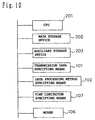
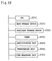
- Figure 2 shows the hardware configuration of the present embodiment for implementing the above-configured system at the transmitting end.
- the configuration shown in Figure 2 is basically the same as that of a general purpose computer system.
- reference numeral 202 is a main storage device constructed from a volatile memory for storing programs
- 203 is an auxiliary storage device constructed from a nonvolatile memory in which programs and other data are stored
- 201 is a CPU for executing the programs stored in the main storage device 202.
- the hardware configuration is basically the same as that of a general purpose computer system, so that any program stored on the auxiliary storage device 203 is first loaded into the main storage device 202 before it can be executed by the CPU 201.
- reference numeral 301 is a receiving unit for receiving data in accordance with a prescribed protocol
- 302 is a received data demultiplexing unit for expanding and demultiplexing the received data
- 303 is a data storing means for storing the demultiplexed data
- 304 is a data processing descriptor storing means for storing the data processing descriptor out of the demultiplexed descriptors
- 305 is a condition descriptor storing means for storing the condition descriptor
- 306 is an event descriptor storing means for storing the event descriptor
- 307 is a data processing unit for processing the data stored in the data storing means 303 in accordance with the data processing descriptor
- 308 is a condition evaluating unit for evaluating the condition in accordance with the condition descriptor
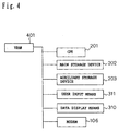
- Figure 4 shows the hardware configuration of the present embodiment for implementing the above-configured system.
- the configuration shown in Figure 4 is basically the same as that of a general purpose computer system.
- Reference numeral 401 is a VRAM for storing image data, etc. for implementing an graphic user interface.
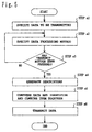
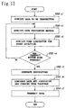
- step a2 Continues to accept the specification of the data processing method being entered in step a2 until the transmit button is pressed. When the transmit button is pressed, the process proceeds to step a4.
- the transmission data combining unit 104 compresses the specified data and the descriptors and combines them together.
- the transmitting unit 105 transmits the data via the modem 106 in accordance with a prescribed protocol, after which the step is terminated.
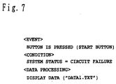
- text data is used as the data to be transmitted, but image data such as GIF or JPEG, image data such as MPEG, or data described using such a language as HTML or XML may also be used.
- binary data (including byte code) or program, executable at the receiving end may be transmitted as the data.
- Such data can be used, for example, for upgrading software at the receiving apparatus side.
- a command or program for directly controlling a device at the receiving side is described in the data processing descriptor, or where display data is described by including it in the data processing descriptor, the main body of the data to be processed need not necessarily be transmitted (this corresponds to claims 13 and 14).
- a modem is used as the communication device, but it will be appreciated that other type of communication device may be used depending on the communication line used (a digital line, the Internet, digital broadcasting, etc.).
- a proprietary protocol may be used as the communication protocol, or any other protocol, such as XMODEM, FTP, HTTP, SMTP, or BFT of G3, may be used.
- the above embodiment has dealt with the simplest example of display as an example of the data processing, but a condition concerning a user profile may be described in the condition descriptor, and processing for editing the contents of data to match the user may be included in the description.
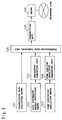
- Figure 9 is a diagram showing the system configuration at the transmitting end according to a second embodiment in the first aspect of the present invention.
- This system configuration includes the same constituent elements as those shown in the system configuration of Figure 1; therefore, the same constituent elements will be designated by the same reference numerals and will not be specifically described herein.
- reference numeral 107 is a time limitation specifying means for specifying a time limitation
- 108 is a time limiting descriptor generating unit for generating an event time limiting descriptor, a condition time limiting descriptor, and a processing time limiting descriptor in accordance with the time limitation specified by the time limitation specifying means 107; here, the transmission data combining unit 104 combines the data including these time limiting descriptors.
- Figure 10 shows the hardware configuration of the present embodiment for implementing the above-configured transmitting system.
- the configuration shown in Figure 10 is basically the same as that of a general purpose computer system. Since this hardware configuration includes the same constituent elements as those shown in the system configuration of Figure 9, the same constituent elements will be designated by the same reference numerals and will not be specifically described herein.
- FIG 11 The system configuration at the receiving end is shown in Figure 11.
- the embodiment shown in Figure 11 concerns the case where only the event time limitation is imposed.
- This system configuration includes the same constituent elements as those shown in the system configuration of Figure 9; therefore, the same constituent elements will be designated by the same reference numerals and will not be specifically described herein.
- reference numeral 312 is an event time limiting descriptor storing means for storing the event time limiting descriptor demultiplexed from the received data
- 313 is an event reception management unit for managing the validity/invalidity of the reception of an event on the basis of the event time limiting descriptor
- 314 is a timing means for holding the current time and measuring a time interval.
- Figure 12 shows the hardware configuration of the present embodiment for implementing the above-configured system.
- the configuration shown in Figure 12 is basically the same as that of a general purpose computer system. Since this hardware configuration includes the same constituent elements as those shown in the system configuration of Figure 2 or 11, the same constituent elements will be designated by the same reference numerals and will not be specifically described herein.
- the method is specified so that prescribed information is displayed when the user presses the apply button. Since one of two different screens is selected for display according to the time limit described hereinafter, the processing for display is specified for each case. If there is no specific condition concerning the display, the condition need not be specified. If the condition is not specified, it is assumed that the condition always holds.
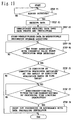
- step c2 Specifies the time limit for the reception of an event.
- art event time limitation is imposed on each of the two different kinds of display processing specified in step c2 so that one is valid through September 30th and the other becomes valid on October 1st.
- step c3 Continues to accept the specification of the time limit being entered in step c3 until the transmit button is pressed. When the transmit button is pressed, the process proceeds to step c5.
- the transmission data combining unit 104 compresses the specified data and each of the descriptors and combines them together.
- the transmitting unit 105 transmits the data via the modem 106 in accordance with a prescribed protocol, after which the step is terminated.
- the present embodiment has dealt with the case where a time limitation is specified only for the event, but it will be appreciated that a time limitation can also be specified for the condition or the data processing.
- a time limitation is specified for the condition or the data processing
- the condition time limiting descriptor or the processing time limiting descriptor is also generated in step c5, and all the descriptors generated are compressed and combined together in step c6.
- the received data is expanded and demultiplexed into the data and the descriptors, i.e., the event time limiting descriptor, the event descriptor, the condition descriptor, and the data processing descriptor.
- the demultiplexed data is stored in the data storing means 303, the data processing descriptor is stored in the data processing descriptor storing means 304, the condition descriptor is stored in the condition descriptor storing means 305, the event descriptor is stored in the event descriptor storing means 306, and the event time limiting descriptor is stored in the event time limiting descriptor storing means 312.
- a time table is generated that is used to manage the periods during which the respective event descriptors are valid.
- the time table is generated such that the descriptor in part (a) of Figure 14 is valid through September 30th and the descriptor in part (b) of Figure 14 is valid from October 1st onward.
- the event receiving unit 309 receives the event associated with the event descriptor currently valid for reception.
- the process proceeds to step d6.
- "APPLY BUTTON IS PRESSED" from the user input means 311 is received as the event regardless of the date (though the condition to be evaluated and the data processing to be performed both differ depending on the date of event reception).
- the condition evaluating unit 308 evaluates the condition described in the condition descriptor associated with the currently valid event descriptor passed from step d6. If the condition is satisfied, the process proceeds to step d8. In this example, since the condition is not specified, it is always assumed that the condition is satisfied.
- the data processing unit 307 processes the data, after which the step is terminated.
- the data processing shown in part (a) of Figure 14 is performed to display the application format, and if the date is October istor later, the data processing shown in part (b) of Figure 14 is performed to display the message "WE HAVE ALREADY CLOSED APPLICATIONS" on the data display means 310.
- the above embodiment has dealt with the simplest example of display as an example of the data processing, but in a sales system, for example, it is possible to describe the processing such that if 80% of the sales target is attained by 18:00, then merchandise will be sold at a discount.
- a rule that can automatically change the method of processing for an event at the receiving end according to the date of the occurrence of the event can be easily created at the transmitting end for transmission. Accordingly, different processing can be performed for the same event, for example, according to the time segment, or processing that is valid only during a certain time segment can be realized.
- reference numeral 315 is a condition time limiting descriptor storing means for storing the condition time limiting descriptor demultiplexed from the received data
- 316 is a condition evaluation control unit for controlling the condition evaluation in accordance with the condition time limiting descriptor.
- the received data is expanded and demultiplexed into the data and the descriptors, i.e., the event descriptor, the condition time limiting descriptor, the condition descriptor, and the data processing descriptor.
- the demultiplexed data is stored in the data storing means 303, the data processing descriptor is stored in the data processing descriptor storing means 304, the condition descriptor is stored in the condition descriptor storing means 305, the event descriptor is stored in the event descriptor storing means 306, and the condition time limiting descriptor is stored in the condition time limiting descriptor storing means 315.
- the event receiving unit 309 receives the event described in the event descriptor. When the event is received, the process proceeds to step e6. In this example, "MERCHANDISE DELIVERED" from the user input means 311 is received as the event.
- a time table for condition evaluation is generated in accordance with the condition time limiting descriptor.
- the condition evaluating unit 308 evaluates the condition by considering the time limit under the control of the condition evaluation control unit 316. If the condition is satisfied, the process proceeds to step e7. In this example, the stock period of the merchandise since its delivery is counted, and when the period exceeds one month, the condition is satisfied.
- the data processing unit 307 Based on the contents of the data processing descriptor associated with the condition descriptor examined in step e6, the data processing unit 307 processes the data, after which the step is terminated. In this example, a report is sent to the center.
- FIG 18 The system configuration at the receiving end is shown in Figure 18.
- This system configuration includes the same constituent elements as those shown in the system configuration of Figure 11; therefore, the same constituent elements will be designated by the same reference numerals and will not be specifically described herein.
- reference numeral 317 is a processing time limiting descriptor storing means for storing the processing time limiting descriptor demultiplexed from the received data
- 318 is a processing time control unit for controlling the time of data processing in accordance with the processing time limiting descriptor.
- the received data is expanded and demultiplexed into the data and the descriptors, i.e., the event descriptor, the condition descriptor, the processing time limiting descriptor, and the data processing descriptor.
- the demultiplexed data is stored in the data storing means 303, the data processing descriptor is stored in the data processing descriptor storing means 304, the condition descriptor is stored in the condition descriptor storing means 305, the event descriptor is stored in the event descriptor storing means 306, and the processing time limiting descriptor is stored in the processing time limiting descriptor storing means 317.
- the event receiving unit 309 receives the event described in the event descriptor. When the event is received, the process proceeds to step f6. In this example, "MESSAGE TRANSMIT REQUEST" from the user input means 311 is received as the event.
- the condition evaluating unit 308 evaluates the condition described in the condition descriptor associated with the valid event descriptor passed from step f5. If the condition is satisfied, the process proceeds to step f7. In this example, if there is no specification of "urgency" in the message requesting a transmission, the condition is satisfied.
- Preparations are made for the processing described in the data processing descriptor associated with the condition descriptor passed from step f6 and, based on the contents of the processing time limiting descriptor, the processing time control unit instructs the data processing unit 307 to start the processing.
- the processing time control unit instructs the data processing unit 307 to start the processing. In this example, if any message to be transmitted is left when the time is past 23:00, the instruction to execute the transmission is given to the data processing unit.
- the data processing unit 301 instructed to start the processing carries out the data processing, after which the step is terminated.
- the message is transmitted.
- FIG. 20 is a diagram showing the system configuration at the transmitting end according to a fifth embodiment of the present invention.
- reference numeral 501 is a signal encoding unit for applying proper encoding operations, including compression, to a broadcast signal
- 502 is an event descriptor encoding unit for encoding an event descriptor in synchronization with the encoding being performed in the signal encoding unit
- 503 is a rule encoding unit for encoding a rule associated with the event descriptor in synchronization with the encoding being performed in the signal encoding unit
- 504 is an additional information encoding unit for encoding additional information in synchronization with the encoding being performed in the signal encoding unit
- 505 is a multiplexing unit for multiplexing the encoded broadcast signal
- descriptor and additional information
- 506 is a transmitting unit for applying processing necessary for transmission, such as channel codec and modulation operations, to the multiplexed signal
- 507 is an up converter for modulating the signal
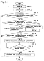
- Figure 21 shows the hardware configuration of the present embodiment for implementing the above-configured system at the transmitting end.
- the configuration shown in Figure 21 is basically the same as that of a general purpose computer system. Since this hardware configuration includes the same constituent elements as those shown in the system configuration of Figure 2 or 20, the same constituent elements will be designated by the same reference numerals and will not be specifically described herein.
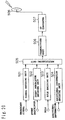
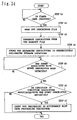
- FIG. 22 The system configuration at the receiving end is shown in Figure 22.
- This system configuration includes the same constituent elements as those shown in the system configuration of Figure 3; therefore, the same constituent elements will be designated by the same reference numerals and will not be specifically described herein.
- reference numeral 701 is a receiving antenna
- 702 is a down converter for modulating the satellite wave received by the receiving antenna into a predetermined lower frequency
- 703 is a digital broadcast receiving tuner
- 704 is a demultiplexing unit for demultiplexing the signal selected by the tuner into the broadcast signal consisting of video and audio information
- 705 is a signal decoding unit for decoding the encoded broadcast signal
- 706 is an event descriptor decoding unit for decoding the encoded event descriptor
- 707 is a rule decoding unit for decoding the encoded rule
- 708 is an additional information decoding unit for decoding the encoded additional information
- 709 is a rule executing unit for
- Figure 23 shows the hardware configuration of the present embodiment for implementing the above-configured system.
- the configuration shown in Figure 23 is basically the same as that of a general purpose computer system. Since this hardware configuration includes the same constituent elements as those shown in the system configuration of Figure. 2 or 22, the same constituent elements will be designated by the same reference numerals and will not be specifically described herein.
- a rule 1 which identifies the reception of additional information as an event and displays a message "RECEIVING ADDITIONAL INFORMATION" on the monitor if onscreen display is enabled
- a rule 2 which identifies the pressing of a display button by the user as an event and displays the contents of the additional information if the additional information is being received.
- the signal encoding unit 501 applies proper encoding operations, including compression, etc. to the broadcast signal consisting of video information, such as a standard television signal or HighVision signal, and its associated audio information.
- step g8 It is examined whether there is additional information associated with the broadcast signal encoded in step g1 and, if there is additional information, the process proceeds to step g3. Otherwise, the process proceeds to step g8.
- the additional information to be multiplexed for transmission is encoded by the additional information encoding unit 504 in the same manner as in step g1.
- the condition for processing the additional information and the contents of the processing are specified in the form of a rule, and an event that triggers the rule is specified.
- Rules and event descriptors are generated in accordance with the specified contents.
- the rule 1 and the rule 2 are specified.
- the descriptors generated here are shown in Figure 25.
- the event descriptor encoding unit 502 encodes the event descriptors.
- the rule encoding unit 503 encodes the rules.
- the encoded broadcast signal, additional information, event descriptors, and rules are supplied to the multiplexing unit 505 for multiplexing.
- the transmitting unit 506 applies necessary processing, such as channel codec and modulation operations, to the signal multiplexed in step g7, and thus modulates the signal into a digital broadcast transmission signal.
- the signal is transmitted toward a broadcast satellite from the transmitting antenna 508 via the up converter 507.
- the satellite wave received by the receiving antenna 701 is down converted by the down converter 702 to the predetermined frequency band, and supplied to the digital broadcast tuner 703 and then to the digital demodulator for frequency selection and demodulation.
- the digital broadcast signal selected and demodulated in step h1 is demultiplexed by the demultiplexing unit 704 into the program information consisting of video and audio information, the event descriptors, the rules, and the additional information.
- the event descriptor decoding unit 706 decodes the event descriptors carried in the received signal.
- the rule decoding unit 707 decodes the rules carried in the received signal.
- the additional information decoding unit 708 decodes the additional information carried in the received signal.
- step h7 Receives an event corresponding to the event descriptors decoded in step h3.
- the process proceeds to step h7.
- the process proceeds to the next step.
- step h6 The condition evaluation and the execution of the rule corresponding to the event descriptor received in step h6 are performed, after which the step is terminated.
- the rule 1 is executed to examine whether onscreen display is enabled or not and, if it is enabled, the message "RECEIVING ADDITIONAL INFORMATION" is displayed on the monitor 710.
- the rule 2 is executed and, if the additional information is being received, the additional information is displayed.
- interrupts to the CPU have been handled as events, but the events used in the present invention are not limited to such events, but generally refer to externally arising events that need not monitoring.
- the program medium of the present invention refers to a program medium, such as a CD, which stores thereon a program for implementing by a computer all or part of each process in the above-described data transmission method, or to a program medium, such as a DVD, which stores thereon a program for implementing by a computer all or part of each process in the above-described data reception processing method.
- Figure 27 is a diagram showing the system configuration at the writing side according to a first embodiment in the second aspect of the present invention.
- reference numeral 101A is a data specifying means for specifying data to be stored
- 102A is a data processing method specifying means for specifying how the data is to be processed at the reading side
- 103A is a descriptor generating unit for generating an event descriptor, a condition descriptor, and a data processing descriptor in accordance with the data processing method specified by the data processing method specifying means 102A
- 104A is a file creating unit for converting the data and the descriptors to a predetermined file format
- 105A is a file writing unit for writing the file created by the file creating unit 104A to a designated storage medium.
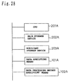
- Figure 28 shows the hardware configuration of the present embodiment for implementing the above-configured system at the writing side.
- the configuration shown in Figure 28 is basically the same as that of a general purpose computer system. Since this hardware configuration includes the same constituent elements as those shown in the system configuration of Figure 27, the same constituent elements will be designated by the same reference numerals and will not be specifically described herein.
- reference numeral 202A is a main storage device constructed from a volatile memory for storing programs
- 203A is an auxiliary storage device constructed from a nonvolatile memory in which programs and other data are stored
- 201A is a CPU for executing the programs stored in the main storage device 202A.
- the hardware configuration is basically the same as that of a general purpose computer system, so that any program stored on the auxiliary storage device 203A is first loaded into the main storage device 202A before it can be executed by the CPU 201A.
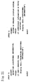
- FIG. 29 The system configuration at the reading side is shown in Figure 29.
- This system configuration includes the same constituent elements as those shown in the system configuration of Figure 27; therefore, the same constituent elements will be designated by the same reference numerals and will not be specifically described herein.
- reference numeral 301A is a file reading unit for reading out a file from a designated storing medium
- 302A is a descriptor separating unit for separating the descriptors by extracting them from the readout file
- 303A is a data processing descriptor storing means for storing the data processing descriptor out of the separated descriptors
- 304A is a condition descriptor storing means for storing the condition descriptor
- 305A is an event descriptor storing means for storing the event
- 306A is a data processing unit for processing the data in accordance with the data processing descriptor
- 307A is a condition evaluating unit for evaluating the condition in accordance with the condition descriptor
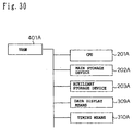
- Figure 30 shows the hardware configuration of the present embodiment for implementing the above-configured system.
- the configuration shown in Figure 30 is basically the same as that of a general purpose computer system. Since this hardware configuration includes the same constituent elements as those shown in the system configuration of Figure 29, the same constituent elements will be designated by the same reference numerals and will not be specifically described herein.
- the description given hereinafter deals with an example in which a message for a family member is created and written to a flash card at the writing side and, when the flash card is inserted at the reading side, the message is displayed upon the arrival of a preset time to display the message.
- a message "PLEASE TAKE IN THE WASHING" is created using a text editor.
- step a2 continues to accept the specification of the data processing method being entered in step a2 until the enter button is pressed.
- the process proceeds to step a4.
- the file creating unit 104A converts the specified data and the descriptors to a predetermined file format.
- An example of a generated file format is shown in Figure 33.
- the set of descriptors is converted to a file named RULE1.TXT, while the data is converted to a file named DATA1.TXT.
- the DATA1.TXT is associated as the display data.
- the file writing unit 105A writes the files to a flash card, upon which the step is terminated.
- the message has been created by entering characters using a text editor, but the characters may be entered using a tablet, or the message may be input in form of voice by using a microphone or in the form of an image by using a camera.
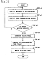
- step b2 It is examined whether the flash card is inserted or not. If the flash card is inserted, the process proceeds to step b2.
- the descriptor file is read out from the file reading unit 106A.
- the respective descriptors i.e., the event descriptor, the condition descriptor, and the data processing descriptor, are separated from the file read out in step b2.
- the data processing descriptor thus separated is stored in the data processing descriptor storing means 303A, the condition descriptor is stored in the condition descriptor storing means 304A, and the event descriptor is stored in the event descriptor storing means 305A.
- the event receiving unit 308A receives the event described in the event descriptor. When the event is received, the process proceeds to step b6. In this example, "TIMER INTERRUPT" from the timing means 310A is received as the event.
- the condition evaluating unit 308A evaluates the condition described in the condition descriptor associated with the event descriptor passed from step b5. If the condition is satisfied, the process proceeds to step b7. In this example, it is examined whether "15:00" is satisfied or not.
- the corresponding data file is read out of the storing medium, and the data is processed by the data processing unit 307A, after which the step is terminated.
- the message "PLEASE TAKE IN THE WASHING" is displayed on the data display means 309A.
- the respective descriptors are automatically read, and waiting mode is entered to wait for the occurrence of an event so that the event described in the event descriptor is automatically received.
- the above embodiment has dealt with the simplest example of message display as an example of the data processing, but it is also possible to present procedures such as a cooking recipe by voice by using the elapsed time as an event.
- the flash card has been taken as an example of the storing medium, but it will be appreciated that other removable media such as a hard disk may be used, or a ROM (read only memory) such as a CD-ROM may be used as the medium.
- ROM read only memory
- the file creating unit in the present embodiment is an example of the file creating means of the present invention
- the file writing unit in the present embodiment is an example of the file writing means of the present invention
- the file reading unit in the present embodiment is an example of the file reading means of the present invention
- the data processing unit, condition evaluating unit, and event receiving unit in the present embodiment are each an example of the data processing means of the present invention.
- event-driven type file creating apparatus event-driven type file reading apparatus, data storing method, and data processing method described above, it becomes possible to implement the writing side, for example, as software of a personal computer and the reading side as an adaptor connected to a television set.
- This not only enables the creation of relatively complex data, but can also make the reading side simple and low cost in construction.
- Another advantage is that since no particular operation is needed at the message viewing side, the system can be used easily even by children and old people.
- Figure 35 is a diagram showing the system configuration at the writing side according to a second embodiment of the present invention.
- the configuration shown in Figure 35 includes the same constituent elements as those shown in the system configuration of Figure 27; therefore, the same constituent elements will be designated by the same reference numerals and will not be specifically described herein.
- reference numeral 501A is a data transmission method specifying means for specifying the telephone number of the data receiving party and the timing for data transmission by time or by an event.
- Figure 36 shows the hardware configuration of the present embodiment for implementing the above-configured system at the writing side.
- the configuration shown in Figure 36 is basically the same as that of a general purpose computer system. Since this hardware configuration includes the same constituent elements as those shown in the system configuration of Figure 28 or 35, the same constituent elements will be designated by the same reference numerals and will not be specifically described herein.
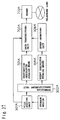
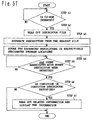
- FIG. 37 The system configuration at the transmitting (reading) side is shown in Figure 37.
- This system configuration includes the same constituent elements as those shown in the system configuration of Figure 29; therefore, the same constituent elements will be designated by the same reference numerals and will not be specifically described herein.
- reference numeral 701A is a destination descriptor storing means for storing a destination descriptor out of the separated descriptors
- 702A is a data transmitting unit for transmitting data associated with the event descriptor in accordance with the destination descriptor
- 703A is a modem.
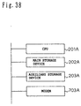
- Figure 38 shows the hardware configuration of the present embodiment for implementing the above-configured system.
- the configuration shown in Figure 38 is basically the same as that of a general purpose computer system. Since this hardware configuration includes the same constituent elements as those shown in the system configuration of Figure 28 or 37, the same constituent elements will be designated by the same reference numerals and will not be specifically described herein.
- the image to be transmitted is selected using the data specifying means 101A.
- the destination and the event for starting the transmission are specified using the transmission method specifying means 501A.
- the transmission method specifying means 501A In this example, assuming that it is desired to start the transmission immediately after the insertion of the flash card, "FLASH CARD IS INSERTED" is specified as the event.
- An example of a screen for specifying the data and the transmission method is shown in Figure 40.
- the file creating unit 104A converts the specified image data and the descriptors to a predetermined file format. Examples of the generated files are shown in Figure 41.
- the file writing unit 105A writes the files generated in step c5 to the flash card, after which the step is terminated.
- step d2 It is examined whether the flash card is inserted or not. If the flash card is inserted, the process proceeds to step d2.
- the descriptor file is read out from the file reading unit 106A.
- the respective descriptors i.e., the event descriptor and the destination descriptor, are separated from the file read out in step d2.
- the destination descriptor thus separated is stored in the destination descriptor storing means 701A, and the event descriptor is stored in the event descriptor storing means 305A.
- the event receiving unit 308A receives the event described in the event descriptor. When the event is received, the process proceeds to step d6. In this example, since "CARD IS INSERTED" is used as the event, it is determined that the event has occurred upon insertion of the card.
- the corresponding data file is read out from the flash card, and the data transmitting unit 702A transmits the data via the modem 703A, after which the step is terminated.
- TIMER COUNT COMPLETED AT SPECIFIED TIME may be used as the event to specify the time so that the data will be transmitted during a time segment where lower charges apply.
- Image data has been taken as an example of the transmission data, but moving image data such as MPEG data, facsimile data, program data, or any other data can be transmitted as long as the data is digital data.
- the writing side may be connected to the telephone line so that the set of the descriptors and data can be downloaded.
- the file creating unit in the present embodiment is an example of the file creating means of the present invention
- the file writing unit in the present embodiment is an example of the file writing means of the present invention
- the data transmission method specifying means in the present embodiment is an example of the data processing method specifying means of the present invention
- the file reading unit in the present embodiment is an example of the file reading means of the present invention
- the data transmitting unit and event receiving unit in the present embodiment are each an example of the data processing means of the present invention.
- the processing for transmission can be accomplished by just inserting the recording medium in the transmission apparatus which is the only one being installed at a place where the telephone line is available; this offers the advantage of being able to eliminate the problem of telephone line routing, etc.
- Figure 43 is a diagram showing the system configuration at the writing side according to a third embodiment of the present invention.
- the configuration shown in Figure 43 includes the same constituent elements as those shown in the system configuration of Figure 27; therefore, the same constituent elements will be designated by the same reference numerals and will not be specifically described herein.
- reference numeral 901A is a heating control data input means for inputting heating control data
- 902A is a heating condition specifying means for specifying the menu number that uses the heating control data and the condition under which the heating control data can be used.
- Figure 44 shows the hardware configuration of the present embodiment for implementing the above-configured system at the writing side.
- the configuration shown in Figure 44 is basically the same as that of a general purpose computer system. Since this hardware configuration includes the same constituent elements as those shown in the system configuration of Figure 28 or 43, the same constituent elements will be designated by the same reference numerals and will not be specifically described herein.
- FIG. 45 The system configuration at the cooking (reading) side is shown in Figure 45.
- This system configuration includes the same constituent elements as those shown in the system configuration of Figure 29; therefore, the same constituent elements will be designated by the same reference numerals and will not be specifically described herein.
- reference numeral 1101A is a heating control unit for performing heating based on the heating control data
- 1102A is a cooking heater
- 1103A is a user input unit for accepting a user input such as a menu number input, the pressing of a start button, etc.
- 1104A is a heating control data storing means for storing the heating control data that the heating control unit 1101A uses.
- Figure 46 shows the hardware configuration of the present embodiment for implementing the above-configured system.
- the configuration shown in Figure 46 is basically the same as that of a general purpose computer system. Since this hardware configuration includes the same constituent elements as those shown in the system configuration of Figure 28 or 45, the same constituent elements will be designated by the same reference numerals and will not be specifically described herein.
- the present embodiment deals with an example in which food is heated by a microwave oven using heating control data recorded on a flash card.
- Heating control data is input from the heating control data input means 901A.
- An example of an input screen is shown in Figure 48.
- the example of Figure 48 shows that the food is first heated at 600 W for 60 seconds and then heated at 800 W for 30 seconds.
- the menu number and the condition such as ambient temperature are specified as the event for writing the heating data. For example, "1" is specified as the menu number, and ambient temperature not lower than 0 degree and not higher than 40 degrees is specified as the condition.
- Steps e1 and e2 are repeated until the heating control data and heating conditions are specified and, when the specification is completed, the process proceeds to step e4.
- the event descriptor and condition descriptor are generated.
- the file creating unit 104A converts the input heating control data and the descriptors to a predetermined file format. Examples of the generated files are shown in Figure 49.
- the file writing unit 105A writes the files generated in step e5 to the flash card, after which the step is terminated.
- step f2 When the flash card is inserted, an interrupt is caused to the CPU. Accordingly, when the flash card is inserted, the process proceeds to step f2.
- the descriptor file is read out from the file reading unit 106A.
- the respective descriptors i.e., the event descriptor and the condition descriptor, are separated from the file read out in step f2.
- condition descriptor thus separated is stored in the condition descriptor storing means 304A, and the event descriptor is stored in the event descriptor storing means 305A.
- the event receiving unit 308A receives the event described in the event descriptor. When the event is received, the process proceeds to step f6. In this example, the menu number input from the user input unit 1103A is received as the event.
- the corresponding event descriptor is retrieved, and it is examined whether the condition defined by the condition descriptor is satisfied or not; if the condition is satisfied, the process proceeds to step f7.
- the corresponding heating control data is read out from the file reading unit 301A, and stored in the heating control data storing means 1104A.
- step f9 When the start button is pressed from the user input unit 1103A, it is determined that the event has occurs. Therefore, when the button is pressed, the process proceeds to step f9.
- the heating control unit 1101A controls the cooking heater 1102A to perform heating. The step is then terminated.
- a flash card has been used as the recording medium, but other media such as a bar code or a magnetic card may be used.
- condition described in the condition descriptor any other condition than the ambient temperature, for example, the temperature inside the oven, the weight of the food, or the like can also be described as the condition.
- the file creating unit in the present embodiment is an example of the file creating means of the present invention
- the file writing unit in the present embodiment is an example of the file writing means of the present invention
- the heating condition specifying means in the present embodiment is an example of the data processing means of the present invention
- the file reading unit in the present embodiment is an example of the file reading means of the present invention
- the heating control unit, condition evaluating unit, and event receiving unit in the present embodiment are each an example of the data processing means of the present invention
- the cooking heater in the present embodiment is an example of the heating means of the present invention.
- heating control data By writing the heating control data as an event-driven type data processing descriptor to the recording medium together with the data at the writing side, as described above, fine heating control can be performed for each menu, and an adjustment to a new menu can also be accomplished easily.
- Figure 51 is a diagram showing the system configuration at the writing side according to a fourth embodiment in the second aspect of the present invention.
- the configuration shown in Figure 51 includes the same constituent elements as those shown in the system configuration of Figure 27; therefore, the same constituent elements will be designated by the same reference numerals and will not be specifically described herein.
- reference numeral 1301A is a related information specifying means for specifying program related information
- 1302A is a display condition specifying means for specifying an event for displaying the related information, such as an action to select a program from a program list, and the condition under which the related information can be displayed.
- Figure 52 shows the hardware configuration of the present embodiment for implementing the above-configured system at the data creating side.
- the configuration shown in Figure 52 is basically the same as that of a general purpose computer system. Since this hardware configuration includes the same constituent elements as those shown in the system configuration of Figure 28 or 51, the same constituent elements will be designated by the same reference numerals and will not be specifically described herein.
- FIG. 53 The system configuration at the display (reading) side is shown in Figure 53.
- This system configuration includes the same constituent elements as those shown in the system configuration of Figure 29; therefore, the same constituent elements will be designated by the same reference numerals and will not be specifically described herein.
- reference numeral 1501A is a related information display means for displaying the related information by reading it from a recording medium
- 1502A is a program selecting means for the user to select the program whose related information he wishes to have displayed.
- Figure 54 shows the hardware configuration of the present embodiment for implementing the above-configured system.
- the configuration shown in Figure 54 is basically the same as that of a general purpose computer system. Since this hardware configuration includes the same constituent elements as those shown in the system configuration of Figure 28 or 53, the same constituent elements will be designated by the same reference numerals and will not be specifically described herein.
- Program related information is specified using the related information specifying means 1301A. It is assumed here that the file name of already created data is specified.
- Program identifier obtained when a program is selected from the program list is specified as the event for displaying the related information. It is assumed here that the condition that the related information is displayed if, by judging from the time, it is determined that the program is not being broadcast at the moment, is given by default as the condition in the condition descriptor. By so defining the condition descriptor, if the same program is selected, the displayed contents differ depending on the time; that is, if the program is being broadcast, the program is displayed as it is broadcast, otherwise, its related information is displayed.
- step g4 When all information to be recorded on the CD-ROM has been selected by repeating the steps g1 and g2, the process proceeds to step g4.
- the event descriptor and condition descriptor are generated for all selected information.
- the file creating unit 104A converts the input related information and the descriptors to a predetermined file format. Examples of the generated files are shown in Figure 56.
- the file writing unit 105A writes the files generated in step g5 onto the CD-ROM master, after which the step is terminated.
- CD-ROMs are pressed from the thus created master.
- step h2 It is examined whether the CD-ROM is inserted or not. If the CD-ROM is inserted, the process proceeds to step h2.
- the descriptor file is read out from the file reading unit 106A.
- the respective descriptors i.e., the event descriptor and the condition descriptor, are separated from the file read out in step f2.
- condition descriptor thus separated is stored in the condition descriptor storing means 304A, and the event descriptor is stored in the event descriptor storing means 305A.
- the event receiving unit 308A receives the event described in the event descriptor. When the event is received, the process proceeds to step f6. In this example, the selection of a program from a program list is received as the event.
- the process proceeds to step f7.
- the scheduled broadcast time segment for the program is compared with the current time obtained from the timing means 310A and, if the current time is outside the scheduled broadcast time segment, it is determined that the condition is satisfied.
- the corresponding related information is read out from the file reading unit 301A, and displayed on the related information display means 1501A, after which the step is terminated.
- Any display method such as a pop-up display, two-screen display, or picture-in-picture, can be used.
- a CD-ROM has been used as the recording medium, but other media such as a ROM, a DVD-ROM, for example,or floppy disk may be used.
- the file creating unit in the present embodiment is an example of the file creating means of the present invention
- the file writing unit in the present embodiment is an example of the file writing means of the present invention
- the display condition specifying means in the present embodiment is an example of the data processing method specifying means of the present invention
- the file reading unit in the present embodiment is an example of the file reading means of the present invention
- the related information display means, condition evaluating unit, and event receiving unit in the present embodiment are each an example of the data processing means of the present invention.
- the event descriptor, condition descriptor, and data processing descriptor of the present invention can be associated with an event time limiting descriptor, condition time limiting descriptor, and processing time limiting descriptor, respectively, to impose time limitations on the respective descriptors.
- reception of the event is enabled only during the time segment defined by the event time limiting descriptor.
- processing time limiting descriptor receives any event outside the defined time segment.
- processing time limiting descriptor When the processing time limiting descriptor is provided, processing of the data is performed during the time segment defined by the processing time limiting descriptor. Thus it becomes possible not to perform data processing outside the defined time segment. In this way, by imposing time limitations, the data processing method can be specified in a more flexible manner.
- interrupts to the CPU have been handled as events, but the events used in the present invention are not limited to such events, but generally refer to externally arising events that need not monitoring.
- each constituent element of the event-driven type file creating apparatus, event-driven type file reading apparatus, data storing method, or data processing method of the present invention may be implemented in software using a computer, or in hardware using a dedicated hardware circuit or device.
- a program recording medium which stores a program for implementing by a computer all or part of the functions of each constituent element of the event-driven type file creating apparatus, event-driven type file reading apparatus, data storing method, or data processing method of the present invention, also falls within the scope of the present invention.
- Figure 58 is a diagram showing the system configuration at the transmitting end according to a first embodiment in the third aspect of the present invention.
- reference numeral 101B is a signal encoding unit for applying proper encoding operations, including compression, etc. to a broadcast signal
- 102B is an identifier 1 encoding unit for encoding an additional information storage location identifier in synchronization with the encoding being performed in the signal encoding unit
- 103B is an identifier 2 encoding unit for encoding a transfer destination identifier in synchronization with the encoding being performed in the signal encoding unit
- 104B is an additional information encoding unit for encoding additional information in synchronization with the encoding being performed in the signal encoding unit
- 105B is a multiplexing unit for multiplexing the encoded broadcast signal
- identifiers identifiers
- 106B is a transmitting unit for applying processing necessary for transmission, such as channel codec and modulation operations, to the
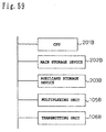
- Figure 59 shows the hardware configuration of the present embodiment for implementing the above-configured system at the transmitting end.
- the configuration shown in Figure 59 is basically the same as that of a general purpose computer system. Since this hardware configuration includes the same constituent elements as those shown in the system configuration of Figure 58, the same constituent elements will be designated by the same reference numerals and will not be specifically described herein.
- reference numeral 202B is a main storage device constructed from a volatile memory for storing programs
- 203B is an auxiliary storage device constructed from a nonvolatile memory in which programs and other data are stored
- 201B is a CPU for executing the programs stored in the main storage device 202B.
- the hardware configuration is basically the same as that of a general purpose computer system, so that any program stored on the auxiliary storage device 203B is first loaded into the main storage device 202B before it can be executed by the CPU 201B.
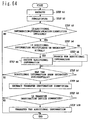
- FIG. 60 The system configuration at the receiving end is shown in Figure 60.
- reference numeral 301B is a receiving antenna
- 302B is a down converter for modulating the satellite wave received by the receiving antenna into a predetermined lower frequency
- 303B is a digital broadcast receiving tuner
- 304B is a demultiplexing unit for demultiplexing the signal selected by the tuner 303B into the broadcast signal consisting of video and audio information
- 305B is a signal decoding unit for decoding the encoded broadcast signal
- 306B is an identifier 1 decoding unit for decoding the encoded additional information storage location identifier
- 307B is an identifier 2 decoding unit for decoding the encoded transfer destination identifier
- 308B is an additional information decoding unit for decoding the encoded additional information
- 309B is a transferring unit for transferring the additional information in accordance with a user device identifier or the transfer destination
- Figure 61 shows the hardware configuration of the present embodiment for implementing the above-configured system.
- the configuration shown in Figure 61 is basically the same as that of a general purpose computer system. Since this hardware configuration includes the same constituent elements as those shown in the system configuration of Figure 59 or 61, the same constituent elements will be designated by the same reference numerals and will not be specifically described herein.
- the signal encoding unit 101B applies proper encoding operations, including compression, etc. to the broadcast signal consisting of video information, such as a standard television signal or HighVision signal, and its associated audio information.
- step a8 it is examined whether there is additional information associated with the broadcast signal encoded in step a1 and, if there is additional information, the process proceeds to step a3. Otherwise, the process proceeds to step a8.
- step a4 it is determined whether the additional information should be transmitted by multiplexing on the broadcast signal; if it should be so transmitted, the process proceeds to step a4. If it should be accessed from the receiving apparatus side via a network or the like, the process proceeds to step a5.
- the additional information to be multiplexed for transmission is encoded by the additional information encoding unit 104B in the same manner as in step a1.
- the storage location of the additional information is specified using prescribed means, and encoding is applied using the identifier 1 encoding unit 102B. If the additional information is to be multiplexed on broadcast signal for transmission, an identifier corresponding to a file name is specified which is used to specify the location of the additional information multiplexed for transmission. If the storage location indicates a file on a network, a URL address as used in an Internet browser or the like is specified.
- maker type or model name of the device for which the additional information is intended is given in accordance with a predetermined naming scheme, and this name is appended as the transfer destination identifier and is encoded by the identifier 2 encoding unit 103B.
- the encoded broadcast signal, additional information, additional information storage location identifier, and transfer destination identifier are supplied to the multiplexing unit 105B for multiplexing.
- the transmitting unit 106B applies necessary processing, such as channel codec and modulation operations, to the signal multiplexed in step a7, and thus modulates the signal into a digital broadcast transmission signal.
- the signal is transmitted toward a broadcast satellite from the transmitting antenna 108B via the up converter 107B.
- Figure 63 shows an example in which the additional information storage location identifier, transfer destination identifier, and additional information are multiplexed for transmission with a cooking program.
- the cooking program consists of video data in slot 1 and audio data in slot 2.
- the additional information storage location identifier, which indicates the storage location of the additional information relating to the cooking program, and the transfer destination identifier, which indicates the device for which the additional information is intended, are paired together, and the thus paired data is transmitted in slot 3.
- the transfer destination identifier can be determined uniquely in accordance with a prescribed naming scheme; for example, if the device is a microwave oven manufactured by Company N, then the name "N-NE-XXXX" (XXXX is the model name ID) or the like is given.
- heating control data for the microwave oven is transmitted in slot 4 as the additional information.
- the heating control data is used in the peripheral device connected at the receiving apparatus side and designated by the transfer destination identifier.
- a device manufacturer can transmit, for example, device control data, or the like as additional information for an advertisement by multiplexing them together, and can thus provide remote service in broadcasting fashion to devices in homes connected by a home bus, IEEE 1394, or the like. For example, if a defect is found in a program built in a product, etc., a corrective measure can be taken quickly and at low cost compared with the traditional method of replacing a ROM.
- the additional information itself need not necessarily be multiplexed on the broadcast signal, but may be obtained via a network. It is obtained by the transferring unit 309B in Figure 60 via the Internet (see the NO branch from the multiplexing step a3 in Figure 62).
- the satellite wave received by the receiving antenna 301B is down converted by the down converter 302B to the predetermined lower frequency, and supplied to the digital broadcast tuner 303B and then to the digital demodulator for frequency selection and demodulation.
- the digital broadcast signal selected and demodulated in step b1 is demultiplexed by the demultiplexing unit 304B into the program information consisting of video and audio information, the additional information storage location identifier, the transfer destination identifier, and the additional information.
- step b4 Using the identifier 1 decoding unit 306B, it is examined whether an additional information storage location identifier is carried in the received signal and, if yes, the process proceeds to step b4. Otherwise, the step is terminated.
- the additional information storage location identifier is analyzed to see whether additional information is multiplexed on the broadcast signal. If additional information is multiplexed on the broadcast signal, the process proceeds to step b5. Otherwise, the process proceeds to step b6.
- the additional information multiplexed on the broadcast signal is decoded by the additional information decoding unit 308B.
- the transferring unit 309B searches for the additional information in accordance with the additional information storage location identifier and, if it is found, the additional information is received by the receiving apparatus. If the additional information is multiplexed, it is transferred from the additional information decoding unit 308B; if the additional information is to be obtained via the Internet, it is transferred from the designated URL.
- step b8 If the additional information is successfully obtained in accordance with the additional information storage location identifier, the process proceeds to step b8. If failed to obtain the additional information, for example, because the additional information storage location is wrong, or the like, the step is terminated.
- the transferring unit 309B receives from the identifier 2 decoding unit 307B the transfer destination identifier extracted from the received signal and designating the peripheral device for which the additional information obtained in step b7 is intended.
- step b10 the step is terminated.
- the transferring unit 309B transfers the additional information to the peripheral device designated by the transfer destination identifier.
- a signal such as shown in Figure 64 described in connection with the transmitting end is received; then, when the cooking program is selected at the receiving end, the received signal is demultiplexed, and the additional information storage location identifier is decoded.
- the additional information since the additional information is multiplexed on the received signal, the additional information is decoded, and further, the transfer destination identifier is decoded.
- the additional information carries new cooking menu data and the transfer destination identifier designates a microwave oven manufactured by Company N. When Company N's microwave oven is connected to the receiving apparatus, then the decoded additional information is transferred to the microwave oven. If it is assumed here that the microwave oven has the function of updating or modifying the cooking data, then with the transferred data a new cooking menu is automatically added without human intervention and becomes ready to use.
- control data such as described above, but any other data such as voice data, image data, driver (firmware), script, executable program, etc; can also be transmitted as the additional data, and in any data format.
- the user device identifier or the transfer destination identifier may be constructed to designate the receiving apparatus itself or an external device having such functions of display, output (printing), storage, etc. In this way, the method of processing the additional information can be set and/or added independently at the user device or destination device side, irrespective of the functions of the receiving apparatus. As a result, the additional information can be used freely at the peripheral device side according to individual needs, for example, allowing the user to print out the information promptly or to temporarily store it.
- the transfer destination identifier to be multiplexed on the broadcast signal may be constructed to designate a plurality of destinations.
- a service called LCR which automatically chooses the lowest cost telephone line has been around for many years, but since this service delivers telephone tariffs over the telephone line, if a fax machine, a telephone, etc. are connected in series, for example, there arises the problem that only the equipment installed on the upstream side can use the service.
- a plurality of communication devices can be configured to receive the LCR service by extracting the user device identifier at the receiving apparatus side and, if the applicable devices are connected to the receiving apparatus, then by extracting the corresponding additional information and transferring it to the devices. If no devices corresponding to the user device identifier are connected, the received additional information is not transferred, but is discarded.
- Information transfer may also be controlled according to user profile information stored in the receiving apparatus by using a transfer condition identifier in addition to the transfer destination identifier.
- a transfer condition identifier in addition to the transfer destination identifier.
- such services as member exclusive service where value added service is provided only to particular users, if the transfer condition identifier is multiplexed for transmission together with the transfer destination identifier, conditions for the transfer can be set to match individual needs.
- program interlinked service can be provided that allows the user to view the picture image of the idol by entering his or her fan club member number from the numeric keypad on the receiving apparatus.
- the third aspect of the present invention provides a transmitting apparatus and receiving apparatus capable of updating firmware, software, or data in peripheral devices utilizing a digital broadcast, by identifying the peripheral devices connected to the receiving apparatus via a home bus or IEEE 1394 and by transferring the additional information, demultiplexed from the transmitted signal, to the peripheral devices designated by the transfer destination identifier at the transmitting apparatus side.
- information can be transferred to any peripheral device designated from the transmitting apparatus side irrespective of the contents or the format of the information, provided that the information transfer is performed in accordance with the protocol between the receiving apparatus and the peripheral device; accordingly, control commands, etc. specific to the peripheral device need not be supported at the receiving apparatus side.
- the data is transferred only when the specified device is connected; therefore; by broadcasting data utilizing a CM broadcast, or the like, maintenance service can be provided simultaneously to all designated devices.
- the present invention also concerns a medium for storing a program that can implement all or part of the means, units, or steps of the invention described above.
- each means or unit may be implemented using dedicated hardware having the equivalent function, or by a computer using software achieving the equivalent function.
- the disadvantage is that the user cannot determine whether or not the data should be transferred to the peripheral device.
- the third aspect of the invention proposes a method for automatically determining whether to transfer or not transfer the data on the basis of the transfer condition identifier, there are cases where the procedure is simpler and more efficient if the user makes the decision on the transfer by himself.
- Figure 65 is a diagram showing the system configuration at the transmitting end according to a first embodiment of the fourth aspect of the present invention.
- reference numeral 101B is a signal encoding unit for applying proper encoding operations, including compression, to a broadcast signal
- 102C is a storage location identifier encoding unit for encoding a storage location identifier in synchronization with the encoding being performed in the signal encoding unit
- 103C is a transfer destination identifier encoding unit for encoding a transfer destination identifier in synchronization with the encoding being performed in the signal encoding unit
- 104C is a user confirmation information encoding unit for encoding user confirmation information in synchronization with the encoding being performed in the signal encoding unit
- 105C is an additional information encoding unit for encoding additional information in synchronization with the encoding being performed in the signal encoding unit
- 106C is a multiplex
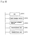
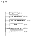
- Figure 66 shows the hardware configuration of the present embodiment for implementing the above-configured system at the transmitting end.
- the configuration shown in Figure 66 is basically the same as that of a general purpose computer system. Since this hardware configuration includes the same constituent elements as those shown in the system configuration of Figure 65, the same constituent elements will be designated by the same reference numerals and will not be specifically described herein.
- reference numeral 202C is a main storage device constructed from a volatile memory for storing programs
- 203C is an auxiliary storage device constructed from a nonvolatile memory in which programs and data are stored
- 201C is a CPU for executing the programs stored in the main storage device 202C.
- the hardware configuration is basically the same as that of a general purpose computer system, so that any program stored on the auxiliary storage device 203C is first loaded into the main storage device 202C before it can be executed by the CPU 201C.
- FIG. 67 The system configuration at the receiving end is shown in Figure 67.
- reference numeral 301C is a receiving antenna
- 302C is a down converter for modulating the satellite wave received by the receiving antenna into a predetermined lower frequency
- 303C is a digital broadcast receiving tuner
- 304C is a demultiplexing unit for demultiplexing the signal selected by the tuner into the broadcast signal consisting of video and audio information
- 305C is a signal decoding unit for decoding the encoded broadcast signal
- 306C is a storage location identifier decoding unit for decoding the encoded storage location identifier
- 307C is a transfer destination identifier decoding unit for decoding the encoded transfer destination identifier
- 308C is an additional information decoding unit for decoding the encoded additional information
- 309C is a user confirmation information descriptor decoding unit for decoding the encoded user confirmation information identifier
- Figure 68 shows the hardware configuration of the present embodiment for implementing the above-configured system.
- The, configuration shown in Figure 68 is basically the same as that of a general purpose computer system.
- the signal encoding unit 101C applies proper encoding operations, including compression, to the broadcast signal consisting of video information, such as a standard television signal or HighVision signal, and its associated audio information.
- step a1 It is examined whether there is additional information associated with the broadcast signal encoded in step a1 and, if there is additional information, the process proceeds to step a3. Otherwise, the process proceeds to step a8.
- step a4 If the additional information should be transmitted by multiplexing on the broadcast signal, the process proceeds to step a4. If it should be accessed from the receiving apparatus side via a network or the like, the process proceeds to step a5.
- the additional information to be multiplexed for transmission is encoded by the additional information encoding unit 104C in the same manner as in step a1.
- the storage location of the additional information is specified, and encoding is applied using the storage location identifier encoding unit 102C. If the additional information is to be multiplexed on the broadcast signal for transmission, an identifier corresponding to a file name is specified which is used to designate the location of the additional information multiplexed for transmission.
- a URL address as used in an Internet browser or the like is specified.
- Maker type or model name of the device for which the additional information is intended is given in accordance with a predetermined naming scheme, and this name is appended as the transfer destination identifier and is encoded by the destination identifier encoding unit 103C.
- the encoded broadcast signal, additional information, additional information storage location identifier, and user device identifier are supplied to the multiplexing unit 106C for multiplexing.
- the transmitting unit 107C applies necessary processing, such as channel codec and modulation operations, to the signal multiplexed in step a8, and thus modulates the signal into a digital broadcast transmission signal.
- the signal is transmitted toward a broadcast satellite from the transmitting antenna 109C via the up converter 108C.
- Figure 70 shows an example in which the storage location identifier, transfer destination identifier, user confirmation information identifier, and additional information are multiplexed for transmission with a CM for a frozen food product.
- the frozen food CM consists of video data in slot 1 and audio data in slot 2.
- the storage location identifier which indicates the storage location of the additional information relating to the frozen food product, and the transfer destination identifier, which designates the device for which the additional information is intended, are paired together, and the thus paired data is transmitted in slot 3.
- the transfer destination identifier can be determined uniquely in accordance with a prescribed naming scheme; for example, if the device is a microwave oven manufactured by Company N, the name "N-NE-XXXX" (XXXX is the model ID) is given.
- microwave oven control data for optimum heating of the frozen food is transmitted in slot 4 as the additional information.
- the control data is used in the microwave oven connected at the receiving apparatus side and designated by the transfer destination identifier.
- the information carried in the user confirmation information descriptor is used, for example, by outputting it to the monitor when transferring the data at the receiving apparatus side.
- device control data can be transmitted after being multiplexed as additional information with the CM, and when the user confirmation information descriptor is used, it becomes possible to confirm on a screen that the data is being transferred when the applicable device is connected.
- the additional information itself need not necessarily be multiplexed on the broadcast signal, but may be obtained via a network. That is, in the broadcast, only information concerning the method of obtaining the additional information may be transmitted, and the actual additional information may be obtained through the Internet or from a dealer. Further, how each identifier or descriptor is to be used at the receiving end is not specifically specified from the transmitting end.
- the satellite wave received by the receiving antenna 301C is down converted by the down converter 302C to the predetermined frequency band, and supplied to the digital demodulator for frequency selection and demodulation via the digital broadcast tuner 303C.
- the digital broadcast signal selected and demodulated in step b1 is demultiplexed by the demultiplexing unit 304C into the program information consisting of video and audio information, the storage location identifier, the transfer destination identifier, and the additional information.
- step b4 Using the identifier 1 decoding unit 306C, it is examined whether a storage location identifier is carried in the received signal and, if yes, the process proceeds to step b4. Otherwise, the step is terminated.
- the storage location identifier is analyzed to see whether additional information is multiplexed on the broadcast signal.
- the additional information multiplexed on the broadcast signal is decoded by the additional information decoding unit 308C.
- Search is made for the additional information in accordance with the storage location identifier and, if it is found, the additional information is received by the receiving apparatus.
- step b8 If the additional information is successfully obtained in accordance with the storage location identifier, the process proceeds to step b8. If failed to obtain the additional information, for example, because the storage location of the additional information is wrong, the step is terminated.
- the user confirmation information descriptor decoding unit 309C extracts from the received signal the user confirmation information descriptor which describes the confirmation information for the user.
- the contents of the user confirmation information descriptor extracted in step b8 are output on the monitor 312C.
- Timer is activated to measure the monitor output time.
- the transfer destination identifier decoding unit 307C extracts from the received signal the transfer destination identifier identifying the peripheral device for which the additional information obtained in step b7 is intended.
- the additional information is transferred to the peripheral device designated by the transfer destination identifier.
- step b14 It is examined whether a prescribed time has elapsed from the activation of the timer; if the prescribed time has elapsed, the process proceeds to step b14 to end the monitor output of the user confirmation information.
- the message "DOWNLOADING HOW-TO-HEAT DATA" is displayed in an overlaid fashion on the monitor for 10 seconds.
- An example of the monitor output is shown in Figure 72.
- the decoded additional information is transferred to the designated microwave oven.
- the microwave oven to which the additional information has been transferred can heat the frozen sweet-and-sour pork using the optimum heating data so it tastes good when eaten.
- the user confirmation information descriptor may be constructed to carry not only the text data to be displayed on the monitor, but also image data or melody or voice data or a combination thereof.
- the user can easily confirm what additional information is being transferred.
- Figure 73 shows the system configuration according to a second embodiment of the present invention.
- the same elements as those shown in the system configuration of Figure 67 will be designated by the same reference numerals and will not be specifically described herein.
- Reference numeral 311C is a transferring unit for transferring additional information in accordance with the user device identifier or transfer destination identifier; the system configuration of this embodiment differs from the system configuration of Figure 67 in that a transfer completion notification can be sent to the user confirmation information descriptor decoding unit.
- Figure 74 shows the hardware configuration of the present embodiment for implementing the above-configured system.
- the configuration shown in Figure 74 is basically the same as that of a general purpose computer system. Since this hardware configuration includes the same constituent elements as those shown in the system configuration of Figure 68, the same constituent elements will be designated by the same reference numerals and will not be specifically described herein.
- the transfer destination identifier decoding unit 307C extracts from the received signal the transfer destination identifier identifying the peripheral device for which the additional information obtained in step b7 is intended.
- the additional information is transferred to the peripheral device designated by the transfer destination identifier.
- step c13 it is examined whether the transfer of the additional information has been completed; if the transfer has been completed, the process proceeds to step c13 to end the monitor output of the user confirmation information.
- the displayed message "DOWNLOADING HOW-TO-HEAT DATA" disappears as soon as the downloading is finished; this is convenient because the user can confirm whether the writing to the microwave oven has been completed or riot.
- Figure 76 shows the system configuration at the receiving end according to a third embodiment of the present invention.
- Reference numeral 501C is a user input unit for accepting an input from the user regarding the display of the user confirmation information.
- Figure 77 shows the hardware configuration of the present embodiment for implementing the above-configured system.
- the configuration shown in Figure 77 is basically the same as that of a general purpose computer system. Since this hardware configuration includes the same constituent elements as those shown in the system configuration of Figure 68 or 76, the same constituent elements will be designated by the same reference numerals and will not be specifically described herein.
- step d11 accepts an input from the user input unit 501.
- the confirm button is pressed, the process proceeds to step d11.
- the transfer destination identifier decoding unit 307C extracts from the received signal the transfer destination identifier identifying the peripheral device for which the additional information obtained in step b7 is intended.
- the additional information is transferred to the peripheral device designated by the transfer destination identifier.
- heating control data for a microwave oven is downloaded from a CM, as in the first embodiment, the transfer, is performed only when the user presses the confirm button during the broadcasting of the CM; this offers the advantage that unnecessary data is not transferred. If a message "PRESS CONFIRM BUTTON TO START TRANSFER" is set in the user confirmation information identifier, the operating procedure is easier to understand.
- Figure 79 shows the system configuration at the receiving end according to a fourth embodiment of the present invention.
- Reference numeral 701C is a destination device status confirming unit for confirming the status of the destination device connected to the receiving apparatus.
- Figure 80 shows the hardware configuration of the present embodiment for implementing the above-configured system.
- the configuration shown in Figure 80 is basically the same as that of a general purpose computer system. Since this hardware configuration includes the same constituent elements as those shown in the system configuration of Figure. 68 or 79, the same constituent elements will be designated by the same reference numerals and will not be specifically described herein.
- the transfer destination identifier decoding unit 307C extracts from the received signal the transfer destination identifier identifying the peripheral device for which the additional information obtained in step b7 is intended.
- step e10 the process waits until the device is ready.
- the additional information is transferred to the peripheral device designated by the transfer destination identifier.
- heating control data for a microwave oven is downloaded from a CM, as in the first embodiment, if the power of the destination device is OFF, the data transfer is started after power is turned on to the device; this offers the advantage of being able to transfer the data without fail.
- Figure 82 shows the system configuration at the receiving end according to a fifth embodiment of the present invention.
- Reference numeral 901C is an identifier storage unit for storing the transfer destination identifier and additional information as a pair.
- Figure 83 shows the hardware configuration of the present embodiment for implementing the above-configured system.
- the configuration shown in Figure 83 is basically the same as that of a general purpose computer system. Since this hardware configuration includes the same constituent elements as those shown in the system configuration of Figures 68 and 82, the same constituent elements will be designated by the same reference numerals and will not be specifically described herein.
- step f10 it is examined whether the destination device designated by the transfer destination identifier is ready to accept data. If the device is ready, the process proceeds to step f10; otherwise, the process proceeds to f11.
- the additional information is transferred to the peripheral device designated by the transfer destination identifier.
- the additional information and the transfer destination identifier are paired and stored in the identifier storage unit.
- a removable medium such as a flash card is used as the identifier storage unit.
- heating control data for a microwave oven is downloaded from a CM, as in the first embodiment, if the destination device is not connected, the data can be stored in the identifier storage unit constructed from a flash card or the like. The stored data can be retrieved when the device is replaced or when a new device is connected.
- Figure 85 shows the system configuration at the receiving end according to a sixth embodiment of the present invention.
- Reference numeral 1101C is a transfer destination candidate identifier decoding unit for decoding an encoded transfer destination candidate identifier
- 1102C is a transfer destination candidate identifier decoding unit for decoding an encoded transfer destination candidate identifier
- 1103C is a transfer destination candidate selecting unit for providing a means for allowing the user to select a transfer destination candidate.
- Figure 86 shows the hardware configuration of the present embodiment for implementing the above-configured system.
- the configuration shown in Figure 86 is basically the same as that of a general purpose computer system. Since this hardware configuration includes the same constituent elements as those shown in the system configuration of Figures 68 and 85, the same constituent elements will be designated by the same reference numerals and will not be specifically described herein.
- the transfer destination candidate descriptor decoding unit 1102C extracts from the received signal the transfer destination identifier identifying the peripheral device for which the additional information obtained in step g is intended.
- the transfer destination descriptor decoding unit 1102C extracts from the received signal the transfer destination candidate descriptor which gives a description about peripheral device candidates that can use the additional information obtained in step g5.
- the transfer destination identifier decoding unit 1101C extracts from the received signal the transfer destination candidate identifier corresponding to the transfer destination candidate descriptor obtained in g9.
- a user selection input is accepted from the transfer destination candidate selecting unit 1103C, and when a valid destination is selected, the process proceeds to step g12.
- the additional information is transferred to the peripheral device designated by the transfer destination candidate identifier selected in step g12.
- data, event, condition, and processing for the data can be transmitted as a set of information.
- the processing can be carried out in accordance with the condition, without increasing the burden of the CPU.
- a set of information consisting of data, event, condition, and processing for the data can be written to a designated recording medium.
- data, a destination descriptor specifying the destination of the data, and an event descriptor specifying the event for starting the transmission can be written as a set of information to a designated storage medium.
- data describing a heating control method, a condition descriptor describing the condition for performing the heating, and an event descriptor specifying the input menu number can be written as a set of information to a designated storage medium.
- program related information a condition descriptor describing the condition for displaying the related information
- an event descriptor in which the selection of a program from an electronic program guide is associated as an event with the related information can be written as a set of information to a designated storage medium.
- the set of information consisting of data, event, condition, and processing for the data can be read out from the designated recording medium and, by evaluating the condition at the timing of reception of the event, the processing can be carried out in accordance with the result of the condition evaluation.
- the data, the destination descriptor specifying the destination of the data, and the event descriptor specifying the event for starting the transmission can be read out from the designated storage medium and, with the event described in the event descriptor as a trigger, the data can be automatically transmitted to the destination described in the destination descriptor.
- the data describing the heating control method, the condition descriptor describing the condition for performing the heating by using the data, and the event descriptor specifying the input menu number can be read out from the designated storage medium, and the heating can be performed based on the data associated with the input menu number.
- the program related information, the condition descriptor describing the condition for displaying the related information, and the event descriptor in which the selection of a program from an electronic program guide is associated as an event with the related information can be read out from the designated storage medium and, when a program is selected from the electronic program guide, the related information can be displayed by evaluating the condition carried in the condition descriptor.
- an additional information storage location identifier indicating the storage location of related additional information and a destination identifier designating a device that can use the additional information are transmitted by multiplexing on a broadcast signal consisting of video information and audio information; at the receiving end, the additional information is extracted from the received signal or obtained through a network by referring to the additional information storage location identifier demultiplexed from the received signal, so that the extracted or obtained additional information can be transferred in accordance with the transfer destination identifier demultiplexed from the received signal.
- the additional information storage location identifier which corresponds to a file name indicating the storage location of the additional information and used to locate the additional information in the transmission signal, and the transfer destination identifier, which designates the device that can use the additional information, are also multiplexed for transmission simultaneously; then, at the receiving end, the new cooking menu as the additional information is extracted and, when an applicable microwave oven is connected to the receiving apparatus, the new cooking menu is transferred to that applicable microwave oven. If, at the applicable microwave oven, a function is provided that automatically adds to or updates its cooking menu when a new cooking menu is transferred to it, a service that can freely add cooking menus for hot-selling frozen food products can be easily realized.
- the additional information storage location identifier indicating the storage location of related additional information and the destination identifier designating a device that can use the additional information are transmitted by multiplexing on the broadcast signal consisting of video information and audio information; at the receiving end, the additional information is extracted from the received signal or obtained through a network by referring to the additional information storage location identifier demultiplexed from the received data, and the user confirmation information descriptor demultiplexed from the received signal is displayed on the screen prompting the user for confirmation, upon which the extracted or obtained additional information can be transferred in accordance with the transfer destination identifier demultiplexed from the received signal.
- This not only serves to retain the advantage that additional information can be readily used through a broadcast or a network, but also serves to avoid trouble such as data being updating before the user is aware of it, or the user being put under the impression that data has been transferred when the device is not connected.
Landscapes
- Engineering & Computer Science (AREA)
- Signal Processing (AREA)
- Multimedia (AREA)
- Computer Networks & Wireless Communication (AREA)
- Physics & Mathematics (AREA)
- Electromagnetism (AREA)
- Two-Way Televisions, Distribution Of Moving Picture Or The Like (AREA)
- Computer And Data Communications (AREA)
- Debugging And Monitoring (AREA)
Applications Claiming Priority (7)
| Application Number | Priority Date | Filing Date | Title |
|---|---|---|---|
| JP17372198 | 1998-06-19 | ||
| JP17372198 | 1998-06-19 | ||
| JP25355598 | 1998-09-08 | ||
| JP25355598 | 1998-09-08 | ||
| JP5112499 | 1999-02-26 | ||
| JP5112499 | 1999-02-26 | ||
| PCT/JP1999/003278 WO1999066679A1 (en) | 1998-06-19 | 1999-06-18 | Data transmitting/receiving method and device, and program recorded medium |
Publications (2)
| Publication Number | Publication Date |
|---|---|
| EP1091531A1 true EP1091531A1 (de) | 2001-04-11 |
| EP1091531A4 EP1091531A4 (de) | 2006-07-26 |
Family
ID=27294214
Family Applications (1)
| Application Number | Title | Priority Date | Filing Date |
|---|---|---|---|
| EP99925389A Ceased EP1091531A4 (de) | 1998-06-19 | 1999-06-18 | Datensende und empfangsverfahren und vorrichtung und medium mit aufgezeichnentem programm |
Country Status (6)
| Country | Link |
|---|---|
| US (1) | US20080209492A1 (de) |
| EP (1) | EP1091531A4 (de) |
| KR (2) | KR100603677B1 (de) |
| CN (1) | CN1311938A (de) |
| AU (1) | AU4169099A (de) |
| WO (1) | WO1999066679A1 (de) |
Cited By (4)
| Publication number | Priority date | Publication date | Assignee | Title |
|---|---|---|---|---|
| WO2003071366A1 (de) * | 2002-02-18 | 2003-08-28 | Infineon Technologies Ag | Ein steuersystem und ein verfahren zum betrieben einer sende-/empfangs-einrichtung |
| WO2003083639A1 (en) * | 2002-04-01 | 2003-10-09 | Matsushita Electric Industrial Co., Ltd. | Receiving device, printer, and firmware update system |
| CN100409166C (zh) * | 2003-02-28 | 2008-08-06 | 松下电器产业株式会社 | 接收装置、打印装置和固件更新系统 |
| US8073439B2 (en) | 2002-02-18 | 2011-12-06 | Infineon Technologies Ag | Control system and method for operating a transceiver |
Families Citing this family (8)
| Publication number | Priority date | Publication date | Assignee | Title |
|---|---|---|---|---|
| KR100697416B1 (ko) * | 2003-09-30 | 2007-03-20 | 교세라 가부시키가이샤 | 모바일 통신 단말기, 정보 제공 시스템 및 프로그램을기록한 컴퓨터 판독가능한 기록 매체 |
| US8233998B2 (en) * | 2004-11-19 | 2012-07-31 | Fisher-Rosemount Systems, Inc. | Secure data write apparatus and methods for use in safety instrumented process control systems |
| KR100782828B1 (ko) * | 2005-12-29 | 2007-12-06 | 삼성전자주식회사 | 디지털 기기에서 알림 메시지를 표시하는 방법 및 상기 알림 메시지 표시 제어 장치 |
| US9497419B2 (en) * | 2007-06-27 | 2016-11-15 | Arris Enterprises, Inc. | Method and apparatus for delivering programming code objects to set-top terminals and the like |
| KR101639645B1 (ko) * | 2008-05-28 | 2016-07-14 | 삼성전자주식회사 | 컨텐트 송신 방법 및 장치와 컨텐트 수신 방법 및 장치 |
| US8700053B2 (en) * | 2010-06-11 | 2014-04-15 | Skyhook Wireless, Inc. | Systems for and methods of determining likelihood of relocation of reference points in a positioning system |
| JP5254411B2 (ja) | 2011-08-31 | 2013-08-07 | 株式会社東芝 | 受信装置、受信方法及び外部装置連携システム |
| US11469937B2 (en) * | 2016-06-02 | 2022-10-11 | Qualcomm Incorporated | Location encoding for synchronization signal to convey additional information |
Family Cites Families (36)
| Publication number | Priority date | Publication date | Assignee | Title |
|---|---|---|---|---|
| US4297557A (en) * | 1976-05-03 | 1981-10-27 | Robertshaw Controls Company | Microwave oven temperature indicator and control means |
| JPS54149435A (en) * | 1978-05-16 | 1979-11-22 | Toshiba Corp | Cooking program input device |
| JP2505770Y2 (ja) * | 1989-05-12 | 1996-07-31 | 船井電機 株式会社 | リモ―トコントロ―ル装置 |
| US5701599A (en) * | 1991-07-30 | 1997-12-23 | Casio Computer Co., Ltd. | Broadcast receiving apparatus having selection function of good reception condition in designated program item |
| DE69331715T2 (de) * | 1992-12-09 | 2002-10-24 | Discovery Communications, Inc. | Fernbedienung für Kabelfernsehverteilsysteme |
| US5648813A (en) * | 1993-10-20 | 1997-07-15 | Matsushita Electric Industrial Co. Ltd. | Graphical-interactive-screen display apparatus and peripheral units |
| US5537141A (en) * | 1994-04-15 | 1996-07-16 | Actv, Inc. | Distance learning system providing individual television participation, audio responses and memory for every student |
| US5819034A (en) * | 1994-04-28 | 1998-10-06 | Thomson Consumer Electronics, Inc. | Apparatus for transmitting and receiving executable applications as for a multimedia system |
| US5563648A (en) * | 1994-04-28 | 1996-10-08 | Thomson Consumer Electronics, Inc. | Method for controlling execution of an audio video interactive program |
| JP3085509B2 (ja) * | 1994-05-12 | 2000-09-11 | 船井電機株式会社 | ビデオ一体型テレビにおける文字表示制御方法 |
| US5768539A (en) * | 1994-05-27 | 1998-06-16 | Bell Atlantic Network Services, Inc. | Downloading applications software through a broadcast channel |
| US5653906A (en) * | 1994-09-07 | 1997-08-05 | Robertshaw Controls Company | Control system for a microwave oven, a microwave oven using such a control system and methods of making the same |
| JPH08129483A (ja) * | 1994-10-31 | 1996-05-21 | Matsushita Electric Ind Co Ltd | イベント駆動型プロセス制御装置 |
| JPH08291914A (ja) * | 1995-04-20 | 1996-11-05 | Fujitsu Ltd | 電子レンジ加熱制御方式 |
| US5659366A (en) * | 1995-05-10 | 1997-08-19 | Matsushita Electric Corporation Of America | Notification system for television receivers |
| BR9608610A (pt) * | 1995-06-07 | 2000-04-25 | Starsight Telecast Inc | Sistema de telivisão com artigos de destaque expansores |
| EP0797342B1 (de) * | 1995-10-11 | 2012-03-14 | Sony Corporation | Informationsleistungsgerät und tragbares kommunikationsendgerät |
| US6157413A (en) * | 1995-11-20 | 2000-12-05 | United Video Properties, Inc. | Interactive special events video signal navigation system |
| US5771064A (en) * | 1995-11-29 | 1998-06-23 | Scientific-Atlanta, Inc. | Home communications terminal having an applications module |
| US6314570B1 (en) * | 1996-02-08 | 2001-11-06 | Matsushita Electric Industrial Co., Ltd. | Data processing apparatus for facilitating data selection and data processing in at television environment with reusable menu structures |
| US5951639A (en) * | 1996-02-14 | 1999-09-14 | Powertv, Inc. | Multicast downloading of software and data modules and their compatibility requirements |
| US5940073A (en) * | 1996-05-03 | 1999-08-17 | Starsight Telecast Inc. | Method and system for displaying other information in a TV program guide |
| JPH1032798A (ja) * | 1996-05-16 | 1998-02-03 | Infuoshitei:Kk | 情報表示方法および装置 |
| US6035304A (en) * | 1996-06-25 | 2000-03-07 | Matsushita Electric Industrial Co., Ltd. | System for storing and playing a multimedia application adding variety of services specific thereto |
| US20020016963A1 (en) * | 1996-08-08 | 2002-02-07 | Hideki Inoue | Information receiving apparatus |
| JP3216534B2 (ja) * | 1996-08-29 | 2001-10-09 | 三菱電機株式会社 | 多重化方法 |
| EP0827336B1 (de) * | 1996-08-30 | 2003-10-15 | Matsushita Electric Industrial Co., Ltd. | Digitales Rundfunksystem, digitale Rundfunkvorrichtung und Empfänger dafür |
| MY118948A (en) * | 1996-09-11 | 2005-02-28 | Matsushita Electric Industrial Co Ltd | Apparatus for controlling the display of data. |
| US6331876B1 (en) * | 1996-11-12 | 2001-12-18 | U.S. Philips Corporation | Method of updating software in a video receiver |
| JPH10177531A (ja) * | 1996-12-16 | 1998-06-30 | Matsushita Electric Ind Co Ltd | スクリプト実行方式 |
| US6449653B2 (en) * | 1997-03-25 | 2002-09-10 | Microsoft Corporation | Interleaved multiple multimedia stream for synchronized transmission over a computer network |
| JP3356961B2 (ja) * | 1997-04-08 | 2002-12-16 | 直之 宮山 | テレビ番組関連情報提供システム |
| US6327418B1 (en) * | 1997-10-10 | 2001-12-04 | Tivo Inc. | Method and apparatus implementing random access and time-based functions on a continuous stream of formatted digital data |
| US6298482B1 (en) * | 1997-11-12 | 2001-10-02 | International Business Machines Corporation | System for two-way digital multimedia broadcast and interactive services |
| US6557171B1 (en) * | 1998-02-02 | 2003-04-29 | Matsushita Electric Industrial Co., Ltd. | Digital tv broadcast sending apparatus, digital tv broadcast receiving apparatus, and digital tv broadcast sending / receiving system which facilitate preselection of tv programs, and computer readable recording medium storing a program for achieving a function of the digital tv broadcast receiving apparatus |
| US6545587B1 (en) * | 1998-03-06 | 2003-04-08 | Matsushita Electric Industrial Co., Ltd. | Bidirectional remote control system, bidirectional remote controller, and device controlled by bidirectional remote controller |
-
1999
- 1999-06-18 KR KR1020067002768A patent/KR100603677B1/ko not_active Expired - Fee Related
- 1999-06-18 CN CN99809250A patent/CN1311938A/zh active Pending
- 1999-06-18 KR KR1020007014447A patent/KR100614347B1/ko not_active Expired - Fee Related
- 1999-06-18 AU AU41690/99A patent/AU4169099A/en not_active Abandoned
- 1999-06-18 EP EP99925389A patent/EP1091531A4/de not_active Ceased
- 1999-06-18 WO PCT/JP1999/003278 patent/WO1999066679A1/ja not_active Ceased
-
2008
- 2008-04-29 US US12/111,576 patent/US20080209492A1/en not_active Abandoned
Cited By (5)
| Publication number | Priority date | Publication date | Assignee | Title |
|---|---|---|---|---|
| WO2003071366A1 (de) * | 2002-02-18 | 2003-08-28 | Infineon Technologies Ag | Ein steuersystem und ein verfahren zum betrieben einer sende-/empfangs-einrichtung |
| US8073439B2 (en) | 2002-02-18 | 2011-12-06 | Infineon Technologies Ag | Control system and method for operating a transceiver |
| WO2003083639A1 (en) * | 2002-04-01 | 2003-10-09 | Matsushita Electric Industrial Co., Ltd. | Receiving device, printer, and firmware update system |
| US7595902B2 (en) | 2002-04-01 | 2009-09-29 | Panasonic Corporation | Receiving device, printer, and firmware update system |
| CN100409166C (zh) * | 2003-02-28 | 2008-08-06 | 松下电器产业株式会社 | 接收装置、打印装置和固件更新系统 |
Also Published As
| Publication number | Publication date |
|---|---|
| KR20010053029A (ko) | 2001-06-25 |
| US20080209492A1 (en) | 2008-08-28 |
| EP1091531A4 (de) | 2006-07-26 |
| WO1999066679A1 (en) | 1999-12-23 |
| KR100603677B1 (ko) | 2006-07-20 |
| KR100614347B1 (ko) | 2006-08-18 |
| AU4169099A (en) | 2000-01-05 |
| CN1311938A (zh) | 2001-09-05 |
| KR20060021417A (ko) | 2006-03-07 |
Similar Documents
| Publication | Publication Date | Title |
|---|---|---|
| US20080209492A1 (en) | Data transmission method, data reception processing method, event-driven type file creating apparatus, event-driven type file reading apparatus, data storing method, data processing method, program recording medium, transmission method, receiving method, and apparatuses for the same | |
| US6732372B2 (en) | Transmission device and terminal device for automatic reception/recording of broadcast programs | |
| AU738484B2 (en) | Method and apparatus for providing a menu structure for an interactive information distribution system | |
| KR100289172B1 (ko) | 텔레비젼 프로그램 전송시스템에서 제공되는 프로그램을 제안하기 위한 재프로그래밍 가능한 터미널 | |
| US20050054337A1 (en) | Mobile telephone with remote-controlling capability, remote-controlling method and system therefor | |
| US7117440B2 (en) | Method and apparatus for providing a menu structure for an interactive information distribution system | |
| JP5459372B2 (ja) | 情報処理装置、情報処理システム、情報処理方法およびプログラム | |
| US7562128B1 (en) | STB connects remote to web site for customized code downloads | |
| EP0851681A1 (de) | Verfahren und Vorrichtung zur Anzeige von Bildern und Daten | |
| JP2001527702A (ja) | ダウンロード可能な特徴を有するテレビジョン・システム | |
| JPH11327717A (ja) | 情報出力装置および情報提供システム | |
| EP1203453B1 (de) | Verbindung einer fernbedienung zu einer web-site zum herunterladen von angepasstem code | |
| US8074252B2 (en) | Communication system, data processing device, data processing method, data providing device, data providing method, and program | |
| EP2040474A1 (de) | Videoabspielvorrichtung, Informationsbereitstellungsvorrichtung, Informationsbereitstellungssystem, Informationsbereitstellungsverfahren und -programm | |
| JP3665509B2 (ja) | 送信方法、受信方法、およびそれらの装置 | |
| EP1203492A1 (de) | Verfahren zur konfiguration eines gerätes der unterhaltungselektronik | |
| JP2007527154A (ja) | ブロードキャストソースを選択するユーザインタフェースをカスタマイズする方法 | |
| KR20110025261A (ko) | 콘텐츠 화면 속에 숨겨진 인터렉티브 서비스를 제공하기 위한 양방향 방송 서비스 방법 및 시스템 | |
| KR100765310B1 (ko) | 내용 선택 | |
| JP2002351912A (ja) | 情報配信システム、それに用いる情報収集作成端末装置、情報提供装置、情報利用端末装置およびそれらを動作させるためのプログラム、そのプログラムが記録された記録媒体、ならびに、情報配信方法 | |
| JP3954042B2 (ja) | データ処理方法、およびデータ処理装置 | |
| HK1034151A (en) | Data transmitting/receiving method and device, and program recorded medium | |
| CN101409668A (zh) | 数据发送及接收的方法与装置以及程序记录媒体 | |
| JP2000138915A (ja) | 有料放送課金制御方法、装置及び有料方法課金制御処理をコンピュータに実現させるためのプログラムを記録した記録媒体 | |
| JP2009157901A (ja) | 情報提供装置、情報表示装置、情報提供システム、情報提供方法、プログラム、およびプログラムを記録したコンピュータ読み取り可能な記録媒体 |
Legal Events
| Date | Code | Title | Description |
|---|---|---|---|
| PUAI | Public reference made under article 153(3) epc to a published international application that has entered the european phase |
Free format text: ORIGINAL CODE: 0009012 |
|
| 17P | Request for examination filed |
Effective date: 20001215 |
|
| AK | Designated contracting states |
Kind code of ref document: A1 Designated state(s): DE FR GB |
|
| RIC1 | Information provided on ipc code assigned before grant |
Ipc: F24C 7/02 20060101ALI20060221BHEP Ipc: H04N 5/44 20060101ALI20060221BHEP Ipc: H04H 1/00 20060101ALI20060221BHEP Ipc: H04N 7/08 20060101ALI20060221BHEP Ipc: H04L 12/56 20060101ALI20060221BHEP Ipc: H04N 7/24 20060101AFI20060221BHEP |
|
| A4 | Supplementary search report drawn up and despatched |
Effective date: 20060626 |
|
| 17Q | First examination report despatched |
Effective date: 20070111 |
|
| REG | Reference to a national code |
Ref country code: HK Ref legal event code: WD Ref document number: 1034151 Country of ref document: HK |
|
| RAP1 | Party data changed (applicant data changed or rights of an application transferred) |
Owner name: PANASONIC CORPORATION |
|
| STAA | Information on the status of an ep patent application or granted ep patent |
Free format text: STATUS: THE APPLICATION HAS BEEN REFUSED |
|
| 18R | Application refused |
Effective date: 20091027 |