EP1091680B1 - Ensemble de fixation d'un sac d'aspirateur - Google Patents
Ensemble de fixation d'un sac d'aspirateur Download PDFInfo
- Publication number
- EP1091680B1 EP1091680B1 EP99926102A EP99926102A EP1091680B1 EP 1091680 B1 EP1091680 B1 EP 1091680B1 EP 99926102 A EP99926102 A EP 99926102A EP 99926102 A EP99926102 A EP 99926102A EP 1091680 B1 EP1091680 B1 EP 1091680B1
- Authority
- EP
- European Patent Office
- Prior art keywords
- bag
- collar
- dirty air
- opening
- mounting member
- Prior art date
- Legal status (The legal status is an assumption and is not a legal conclusion. Google has not performed a legal analysis and makes no representation as to the accuracy of the status listed.)
- Expired - Lifetime
Links
Images


Classifications
-
- A—HUMAN NECESSITIES
- A47—FURNITURE; DOMESTIC ARTICLES OR APPLIANCES; COFFEE MILLS; SPICE MILLS; SUCTION CLEANERS IN GENERAL
- A47L—DOMESTIC WASHING OR CLEANING; SUCTION CLEANERS IN GENERAL
- A47L9/00—Details or accessories of suction cleaners, e.g. mechanical means for controlling the suction or for effecting pulsating action; Storing devices specially adapted to suction cleaners or parts thereof; Carrying-vehicles specially adapted for suction cleaners
- A47L9/10—Filters; Dust separators; Dust removal; Automatic exchange of filters
- A47L9/14—Bags or the like; Rigid filtering receptacles; Attachment of, or closures for, bags or receptacles
- A47L9/1427—Means for mounting or attaching bags or filtering receptacles in suction cleaners; Adapters
-
- Y—GENERAL TAGGING OF NEW TECHNOLOGICAL DEVELOPMENTS; GENERAL TAGGING OF CROSS-SECTIONAL TECHNOLOGIES SPANNING OVER SEVERAL SECTIONS OF THE IPC; TECHNICAL SUBJECTS COVERED BY FORMER USPC CROSS-REFERENCE ART COLLECTIONS [XRACs] AND DIGESTS
- Y10—TECHNICAL SUBJECTS COVERED BY FORMER USPC
- Y10S—TECHNICAL SUBJECTS COVERED BY FORMER USPC CROSS-REFERENCE ART COLLECTIONS [XRACs] AND DIGESTS
- Y10S55/00—Gas separation
- Y10S55/02—Vacuum cleaner bags
Definitions
- the invention is directed to a bag docking assembly and, more particularly, to an assembly for docking a vacuum bag in the proper orientation for engagement with a dirty air outlet nozzle on a vacuum cleaner, and for retaining the vacuum bag in the position of engagement.
- Vacuum cleaners such as upright vacuums, remove dirt from a carpet by creating a suction strong enough to draw the dirt particles from a section of the carpet up into the vacuum cleaner where the dirty air is passed through a vacuum bag in which the entrained dirt is captured.
- a base portion of the vacuum cleaner often has a roller brush for agitating dirt from the carpet as it is being vacuumed.
- a dirty air conduit transfers the dirty air from the base of the vacuum cleaner to the vacuum bag.
- the dirty air conduit runs up a handle assembly or, in cases where the dirty air conduit is rigid, the dirty air conduit can itself function as a portion of the handle.
- a dirty air outlet nozzle At the end of the dirty air conduit opposite the floor there is a dirty air outlet nozzle where the dirty air exits from the dirty air conduit.
- the vacuum bag is attached to the dirty air outlet nozzle.
- the vacuum bag has a bag opening that fits closely over the dirty air outlet nozzle.
- the vacuum bag is otherwise a completely closed bag that is made from a porous material that allows air to flow through it, but which is too fine for most dirt particles to pass through. As dirty air passes through the vacuum bag, the air is forced through the porous material and the dirt is trapped in the bag. The bag thus collects the dirt from the dirty air and, more importantly, from the floor. Because the material of the vacuum bag is often fragile and can get very dusty, the vacuum bag is commonly held within a protective outer bag.
- the outer bag is typically placed over the dirty air outlet nozzle first, with the dirty air outlet nozzle extending through a hole in the outer bag.
- a clip is then forced over the dirty air outlet nozzle between the outer bag and a protrusion on the outer surface of the dirty air outlet nozzle.
- the clip retains the outer bag in the proper position for use.
- the vacuum bag is placed over the remaining length of the dirty air outlet nozzle, and the outer bag closed.
- vacuum bags have been modified over the years to be disposable. This allows the user to merely discard the dirty vacuum bag and replace it with a new, clean one.
- the bags have been designed so that the bag opening can be releasably engaged with the dirty air outlet nozzle.
- One common vacuum bag design incorporates a reinforced area, known as a collar, surrounding the bag opening.
- the collar is usually a square or rectangular piece of thin cardboard.
- the collar can be designed with an elastic seal extending inward from the circumference of the bag opening to further seal the gap between the dirty air outlet nozzle and the bag opening.
- U.S. Patent No. 5,688,298 to Bosses attempts to solve the problem of aligning the vacuum bag with the dirty air outlet nozzle by adding an additional layer on the surface of the collar.
- the additional layer has a large, circular opening. The user can lightly press the face of the collar against the dirty air outlet nozzle and move the collar around until the dirty air outlet nozzle falls into the gap created by the additional layer. This lets the user know that the collar is in the proper position to be pressed against the dirty air outlet nozzle.
- This design does not incorporate any additional features to help retain the collar on the dirty air outlet nozzle.
- the Kopko et al. invention is limited to use on vacuum cleaners having rigid housings. Without a rigid housing, the invention does not provide or suggest any place to attached the hinge. Another problem is that the hinge is designed with positive stops at the rotational limits. The mounting plate is thus only free to rotate over a limited angle. This limits the number of orientations in which the invention may be applied.
- the vacuum cleaner filter bag mounting assembly comprises a bag mounting member having a fixed plate which is secured to a housing of a vacuum cleaner and a hinge plate which is pivotally mounted to the fixed plate through a living hinge.
- a channel is formed on the outside surface of the hinge plate for a receipt of the vacuum bag collar and an air deflector extends outwardly from the fixed plate for insertion into the filter bag.
- An outlet tube is integrally molded to the fixed plate and has bag-retaining projections on an outer surface and a deflector at the end to deflect particles downwardly into the filter bag. The filter bag is retained in the operating condition by the bag-retaining projections on the outlet tube.
- the invention also serves to retain an outer bag to the vacuum cleaner.
- the invention is directed to a vacuum cleaner bag docking assembly for use with vacuum cleaner bags of the type having a substantially rigid mounting collar surrounding the bag opening.
- the assembly incorporates an anchor member and a mounting member.
- a vacuum cleaner bag docking assembly for use with a vacuum bag having a substantially rigid mounting collar surrounding a bag opening and a vacuum cleaner having a dirty air outlet nozzle configured to project through the bag opening and into the vacuum bag, the assembly comprising: an anchor member and a mounting member, the mounting member having a portion thereof for engaging the collar to secure the vacuum bag to the mounting member for movement therewith, the mounting member having a portion thereof defining an opening in registration with the bag opening, the mounting member pivotally connected to the anchor member and being movable between a loading position in which the vacuum bag is inserted into or removed from the mounting member and a working position in which the bag opening engages the dirty air outlet nozzle, characterised in that the anchor member comprises a central opening for closely, releasably receiving the dirty air outlet nozzle, the anchor member being sufficiently deformable to permit the central opening to be engaged with or removed from the dirty air outlet nozzle, and the mounting member being releasably connected to the anchor member and restricting deformation of the anchor member when
- the anchor member can be slid over the dirty air outlet nozzle with the central opening in the anchor member closely fitting around the perimeter of the dirty air outlet nozzle.
- the edge having the hinge member is preferably oriented at the bottom.
- the resilient material of the anchor member is forced beyond a rim or similar protrusion on the dirty air outlet nozzle, and the rim holds the anchor member in place against the handle assembly of the vacuum cleaner.
- the mounting member is pivotally connected to the anchor member by engagement of the first and second hinge members.
- the mounting member is free to rotate over an angle of approximately 180 degrees, from the point where the mounting member abuts the anchor member (the working position) to the point where the mounting member abuts the vacuum cleaner handle. At some point between the two angles, the mounting member is in a position that is convenient for the insertion and removal of the bag collar from the mounting member (the loading position).
- the opening in the mounting member is adapted to closely receive the anchor member when the assembly is in the working position.
- a latch can retain the mounting member against the anchor member, thereby retaining the vacuum bag in the position of engagement with the dirty air outlet nozzle.
- the latch can be a resilient protrusion extending from the perimeter of the anchor member. When the mounting member is pivoted to engage the anchor member, the protrusion is forced through the opening and retains the assembly in the working position.
- the present invention is directed toward a vacuum cleaner bag docking assembly for docking a vacuum cleaner bag in the proper orientation for engagement with a dirty air outlet nozzle on a vacuum cleaner, and for retaining the vacuum bag in the position of engagement.
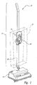
- FIG. 1 shows a bag docking assembly 10 according to one embodiment of the present invention in a position of engagement with an upright vacuum cleaner 12.
- the vacuum cleaner 12 has a base 14 and a handle assembly 16.
- a portion of the handle assembly 16 is a hollow tube serving as a dirty air conduit 18.
- the dirty air conduit 18 connects the base 14 with a dirty air outlet nozzle 20.
- the dirty air conduit 18 can also be independent of the handle assembly 16.
- the bag docking assembly 10 is preferably removably attached to the dirty air outlet nozzle 20.
- a protective, outer bag 22 can be positioned around both the dirty air outlet nozzle 20 and the bag docking assembly 10.
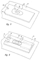
- the bag docking assembly 10 incorporates an anchor member 36 and a mounting member 38.
- the structure and operation of both the anchor member 36 and the mounting member 38 are discussed in detail below.
- the anchor member 36 retains the bag docking assembly 10 to the vacuum cleaner 12.
- the mounting member 38 is pivotally attached to the anchor member 36.
- the mounting member 38 pivots between a loading position, in which the collar 28 of the vacuum bag may be engaged or disengaged with the mounting member 38, and a working position, in which the bag opening 26 engages the dirty air outlet nozzle 20.
- the anchor member 36 is constructed to have an entrance channel 44 at one point about the perimeter of the anchor member 36 to allow the anchor member 36 to be inserted over the dirty air outlet nozzle 20 from a transverse direction.
- the entrance channel 44 is contiguous with the central opening 40 in the anchor member 36, and is separated from the central opening 40 by a reduced neck 46.
- the neck 46 is resilient enough to deform as it passes over the dirty air outlet nozzle 20 and return to its original shape once fully engaged. The neck 46 thus holds the anchor member 36 to the dirty air outlet nozzle 20.
- the anchor member 36 is first positioned adjacent the dirty air outlet nozzle 20 with the general plane of the anchor member 36 on the side of rim 43 closest to the handle assembly 16. The anchor member is slid in a direction transverse to the dirty air outlet nozzle 20 until the dirty air outlet nozzle 20 is completely engaged with the central opening 40. The anchor member 20 is then urged against the rim 43 until the recess in the shoulder 42 closely contacts the rim 43.
- the outer bag 22 can be interposed between the anchor member 20 and the handle assembly 16 to urge the anchor member 20 against the rim 43, or other biasing means can be substituted (Figure 1).
- the mounting member 38 is formed of a plastic that has been injection molded into a substantially planar body.
- the mounting member 38 is formed with an opening 52 that is positioned to correspond with the bag opening 26 when the collar 28 of the vacuum bag 24 is retained within the mounting member 38 in the proper position for engagement with the dirty air outlet nozzle 20 on the vacuum cleaner 12 ( Figure 2), as discussed in more detail below.
- the opening 52 in the mounting member 38 is large enough to engage the perimeter of the anchor member 36.
- the perimeter of the mounting member 38 may also have a retainer member 60 ( Figure 6) that extends from the perimeter of the mounting member 38 toward the center of the opening 52.
- the retainer member 60 is positioned to engage the retainer opening 34 in the collar 28 of the vacuum bag 24.
- the mounting member 38 is shaped to receive a collar 28 having a chamfered corner 64.
- the collar 28 in this particular arrangement has two opposing side margins and an end margin connecting the two side margins ( Figure 8).
- One or both of the corners between the side margins and the end margin can be chamfered 64.
- the mounting member 38 can be formed with one or more corresponding chamfered corners 62.
- the bag docking assembly 10 is engaged with the dirty air outlet nozzle 20 on the vacuum cleaner 12.
- the outer bag 22 can first be positioned over the dirty air outlet nozzle 20, and the bag docking assembly 10 is then positioned to hold the outer bag 22 in place.
- the anchor member 36 can be installed by first positioning the central opening 40 in the anchor member 36 directly over the dirty air outlet nozzle 20. The anchor member 36 is then pressed so that a protrusion or a rim 43 on the dirty air outlet nozzle 20 is forced through the central opening 40 in the anchor member 36.
- the shape of the central opening 40 in the anchor member 36 is close enough to the shape of the dirty air outlet nozzle 20 that the rim 43 on the dirty air outlet nozzle 20 retains the anchor member in its proper position for operation.
- the engagement of first hinge member 48 with second hinge member 58 prevents the entrance channel 44 from distorting, locking the anchor member 36 onto the dirty air outlet nozzle 20.
- the anchor member 36 can also be installed by having the engagement section 44 engage the dirty air outlet nozzle 20 from a transverse direction.
- the neck 46 is forced over the dirty air outlet nozzle 20 and resiliently recovers its original shape, holding the anchor member 36 onto the dirty air outlet nozzle 20.
- the rim 43 on the dirty air outlet nozzle 20 prevents the anchor member 36 from sliding off of the end of the dirty air outlet nozzle 20.
- the mounting member 38 is pivotally attached to the anchor member 36 by the engagement of the first hinge member 48 and the second hinge member 58.
- the pivoting axis is substantially horizontal. Consequently, the mounting member 38 can rotate to a vertical orientation, as shown in Figure 1, in which the second hinge member 58 is at the bottom, i.e., into the working position. From the working position, the mounting member 38 can rotate 180 degrees to a position in which the second hinge member 58 is at the top of the mounting member 38. Between these two positions, the mounting member 38 pivots through a number of orientations in which the mounting member 38 is directed away from the handle assembly 16 and toward the opening of the outer bag 22. In at least one of these positions, defined as a loading position, a user can remove a full vacuum bag 24 from the mounting member 38 and replace it with a new vacuum bag 24. The loading position can be separated from the working position by an angle greater than 90 degrees.
- the vacuum bag 24 can be engaged with the bag docking assembly 10 by inserting the collar 28 between the channels 54 on the mounting member 38.
- the bag opening 26 aligns with the opening 52 in the mounting member 38.
- the bag docking assembly 10 is rotated into the working position, the bag opening 26 aligns with and engages the dirty air outlet nozzle 20.
- the collar 28 is formed to have a sliding panel 32 that can move between an open and a closed position across the bag opening 26 ( Figure 6).
- the retainer member 60 has a substantially hemi-spherical portion 61 at its distal end having a beveled front edge 63 that engages the retainer opening 34 when the collar 28 is fully engaged with the mounting member 38.
- the engagement of the retainer member 60 with the retainer opening 34 operates to close the sliding panel 32 over the bag opening 26 upon removal of the vacuum bag 24 from the mounting member 38.
- the hemi-spherical portion 61 of the retainer member 60 resists the force exerted by the user.
- the force necessary to move the sliding panel 32 is less than the force necessary to disengage the retainer member 60 from the retainer opening 34.
- the sliding panel 32 remains stationary as the collar 28 is removed from the mounting member 38.
- a positive stop 66 in the collar 28 prevents the sliding panel 32 from sliding further.
- all of the force exerted by the user is transferred to the retainer member 60. This additional force frees the retainer opening 34 from the retainer member 60 and disengages the vacuum bag 24 from the mounting member 38.
Landscapes
- Engineering & Computer Science (AREA)
- Mechanical Engineering (AREA)
- Filters For Electric Vacuum Cleaners (AREA)
Claims (18)
- Ensemble de fixation de sac d'aspirateur (10) pour utilisation avec un sac d'aspirateur ayant une collerette de montage sensiblement rigide (28) entourant une ouverture de sac (26) et un aspirateur ayant une buse de sortie d'air sale (20) configurée pour dépasser à travers l'ouverture de sac (26) et dans le sac d'aspirateur, l'ensemble comportant :un élément d'ancrage (36) et un élément de montage (38), l'élément de montage (38) ayant une partie destinée à engager la collerette (28) afin de fixer le sac d'aspirateur sur l'élément de montage pour un mouvement avec celui-ci, l'élément de montage ayant une partie définissant une ouverture en alignement avec l'ouverture de sac, l'élément de montage (38) étant relié de façon pivotante à l'élément d'ancrage (36) et étant mobile entre une position de chargement dans laquelle le sac d'aspirateur est inséré dans ou enlevé de l'élément de montage (38) et une position de travail dans laquelle l'ouverture de sac (26) engage la buse de sortie d'air sale (20), caractérisé en ce quel'élément d'ancrage (36) comprend une ouverture centrale (40) afin de recevoir de manière intime et libérable la buse de sortie d'air sale (20), l'élément d'ancrage (36) étant suffisamment déformable pour permettre à l'ouverture centrale (40) d'être engagée avec ou enlevée de la buse de sortie d'air sale (20), etl'élément de montage (38) étant relié de façon libérable à l'élément d'ancrage (36) et limitant une déformation de l'élément d'ancrage (38) lorsqu'il y est relié afin d'empêcher l'élément d'ancrage (38) d'être retiré de la buse (20).
- Ensemble selon la revendication 1, dans lequel la buse de sortie d'air sale (20) a une section d'engagement (43) destinée à recevoir l'élément d'ancrage (36); l'élément d'ancrage (36) se compose d'une matière élastique; et l'élément d'ancrage (36) a un canal d'entrée (44) continu avec l'ouverture centrale (40) et un étranglement (46) en un point le long du canal d'entrée (44) qui est plus étroite que la section d'engagement (43), l'élément d'ancrage (36) étant suffisamment déformable de manière élastique lorsque l'élément de montage (38) est désengagé afin de permettre à l'élément d'ancrage (36) d'être monté sur ou enlevé de la buse de sortie d'air sale (20) et suffisamment rigide lorsque l'élément de montage (38) est engagé avec afin d'empêcher l'élément d'ancrage (36) d'être enlevé de la buse de sortie d'air sale (20).
- Ensemble selon la revendication 1, dans lequel la position de chargement est séparée de la position de travail d'un angle supérieur à 90°.
- Ensemble selon la revendication 1, dans lequel l'élément de montage (38) est sensiblement plan, l'élément d'ancrage (36) est sensiblement plan, et l'élément d'ancrage (36) est construit afin d'avoir une forme complémentaire à une ouverture (52) dans l'élément de montage (38) de telle sorte que l'ensemble est sensiblement plan lorsqu'il est dans la position de travail.
- Ensemble selon la revendication 4, comportant en outre un verrou (50) pouvant agir afin de retenir de façon libérable l'ensemble dans la position de travail.
- Ensemble selon la revendication 5, dans lequel le verrou (50) comprend une saillie (50) qui s'étend depuis le bord de l'élément d'ancrage (36) qui engage l'ouverture dans l'élément de montage lorsque l'ensemble est dans la position de travail.
- Ensemble selon la revendication 1, comportant en outre une protubérance (60) sur l'élément de montage (38) positionnée afin d'être reçue par une ouverture de retenue (34) dans la collerette (28) afin de maintenir le sac en place après l'insertion.
- Ensemble selon la revendication 7, dans lequel ladite ouverture de retenue (34) est positionnée sur un panneau coulissant (32) dans la collerette (28) et dans lequel la protubérance (60) est disposée sur l'élément de montage (38) de telle sorte que le retrait de la collerette (28) de l'élément de montage (38) alors que la protubérance (60) est engagée avec l'ouverture de retenue (34) amène le panneau coulissant (32) à se déplacer depuis une position ouverte dans laquelle de la saleté peut entrer et sortir de l'ouverture de sac (26) vers une position fermée dans laquelle de la saleté est empêchée d'entrer ou de sortir de l'ouverture de sac (26).
- Aspirateur comportant un ensemble de poignée (16), au moins une partie de celui-ci comportant une conduite d'air sale (18), un sac d'aspirateur (24) ayant une collerette de montage sensiblement rigide (28) entourant une ouverture de sac (26), une buse de sortie d'air sale (20) montée sur l'ensemble de poignée, la buse communiquant avec la conduite d'air sale (18) et dépassant de la conduite d'air sale (18) pour engagement avec le sac d'aspirateur et un ensemble de fixation de sac d'aspirateur selon la revendication 1.
- Aspirateur selon la revendication 9, dans lequel la collerette de montage (28) possède un bord d'extrémité, un premier bord latéral, et un deuxième bord latéral opposé au premier bord latéral, et une surface d'orientation (64), les premier et deuxième bords latéraux étant dans une orientation globalement verticale pendant l'utilisation, le bord d'extrémité étant dans une orientation globalement horizontale pendant l'utilisation, les premier et deuxième bords latéraux étant dégagés du sac, la surface d'orientation (64) comportant une surface inclinée s'étendant depuis le premier bord latéral jusqu'au bord d'extrémité, et la surface d'orientation étant prévue pour orienter l'ouverture du sac.
- Aspirateur selon la revendication 10, dans lequel la surface d'orientation (64) comprend un coin chanfreiné de la collerette (28).
- Aspirateur selon la revendication 10, dans lequel la collerette (28) comprend une deuxième surface d'orientation s'étendant depuis le deuxième bord latéral jusqu'au bord d'extrémité.
- Aspirateur selon la revendication 10, dans lequel la collerette (28) comprend en outre une ouverture de retenue (34).
- Aspirateur selon la revendication 10, dans lequel la collerette (28) comprend en outre un renfoncement adjacent au bord d'extrémité (65).
- Aspirateur selon la revendication 10, dans lequel la collerette (28) comprend en outre un joint élastique (30) qui entoure l'ouverture de sac (26).
- Aspirateur selon la revendication 10, dans lequel la collerette (28) comprend en outre un panneau coulissant (32) qui coulisse entre une position ouverte et une position fermée au-dessus de l'ouverture de sac (26).
- Aspirateur selon la revendication 16, dans lequel la collerette (28) comprend en outre une butée positive (66) limitant le mouvement du panneau coulissant (32).
- Aspirateur selon la revendication 16, dans lequel la collerette (28) comprend en outre une ouverture de retenue (34).
Applications Claiming Priority (3)
| Application Number | Priority Date | Filing Date | Title |
|---|---|---|---|
| US107710 | 1998-06-30 | ||
| US09/107,710 US6033451A (en) | 1998-06-30 | 1998-06-30 | Vacuum cleaner bag docking assembly |
| PCT/US1999/012114 WO2000000074A1 (fr) | 1998-06-30 | 1999-06-01 | Ensemble de fixation d'un sac d'aspirateur |
Publications (2)
| Publication Number | Publication Date |
|---|---|
| EP1091680A1 EP1091680A1 (fr) | 2001-04-18 |
| EP1091680B1 true EP1091680B1 (fr) | 2007-08-15 |
Family
ID=22318045
Family Applications (1)
| Application Number | Title | Priority Date | Filing Date |
|---|---|---|---|
| EP99926102A Expired - Lifetime EP1091680B1 (fr) | 1998-06-30 | 1999-06-01 | Ensemble de fixation d'un sac d'aspirateur |
Country Status (7)
| Country | Link |
|---|---|
| US (2) | US6033451A (fr) |
| EP (1) | EP1091680B1 (fr) |
| JP (1) | JP3507034B2 (fr) |
| AU (1) | AU4226099A (fr) |
| CA (1) | CA2335860C (fr) |
| DE (1) | DE69936861T2 (fr) |
| WO (1) | WO2000000074A1 (fr) |
Families Citing this family (35)
| Publication number | Priority date | Publication date | Assignee | Title |
|---|---|---|---|---|
| US6280506B1 (en) * | 1999-04-06 | 2001-08-28 | Oreck Holdings, Llc | Vacuum cleaner inner bag |
| US6379408B1 (en) * | 1999-04-06 | 2002-04-30 | Oreck Holdings, Llc | Mounting and closure structure for a bag, such as a vacuum cleaner bag |
| US6277165B1 (en) | 2000-04-26 | 2001-08-21 | Donna M. Lovett | Vacuum cleaner bag |
| US6446303B1 (en) * | 2000-09-29 | 2002-09-10 | Oreck Holdings, Llc | Bag assembly for a vacuum cleaner |
| US6406507B1 (en) * | 2000-09-29 | 2002-06-18 | Oreck Holdings, Llc | Apparatus and methods for supporting and shielding flexible outer bags of vacuum cleaners |
| US7024724B2 (en) * | 2002-09-10 | 2006-04-11 | Global Technologies Llc | Vacuum, cleaner bag docking assembly |
| US7468083B2 (en) * | 2003-11-07 | 2008-12-23 | Panasonic Corporation Of North America | Vacuum cleaner equipped with bag mount and separate bag caddy |
| US20060242787A1 (en) * | 2005-04-27 | 2006-11-02 | Bosses Mark D | Vacuum bag mounting assembly |
| US7325272B2 (en) * | 2005-09-30 | 2008-02-05 | Bosses Mark D | Vacuum bag guide with telescopic nozzle |
| US7254865B2 (en) * | 2005-09-30 | 2007-08-14 | Bosses Mark D | Vacuum bag guide with telescopic nozzle |
| US7662200B2 (en) * | 2005-10-18 | 2010-02-16 | Electrolux Home Care Products, Inc. | Vacuum bag mounting and viewing features |
| US20070095031A1 (en) * | 2005-11-03 | 2007-05-03 | Zahuranec Terry L | Mounting collar for a filter bag |
| USD559483S1 (en) | 2006-01-25 | 2008-01-08 | Johnsondiversey, Inc. | Vacuum bag attachment |
| US7799107B2 (en) * | 2006-03-15 | 2010-09-21 | Techtronic Floor Care Technology Limited | Self-sealing bag arrangement for a floor cleaning device |
| US7794516B2 (en) | 2008-04-09 | 2010-09-14 | The Scott Fetzer Company | Filter bag mounting assembly |
| US8347453B2 (en) * | 2008-09-04 | 2013-01-08 | Techtronic Floor Care Technology Limited | Vacuum cleaner bag docking assembly |
| US8528166B2 (en) | 2010-04-30 | 2013-09-10 | Techtronic Floor Care Technology Limited | Upright vacuum with floating head |
| US8956432B2 (en) * | 2010-06-18 | 2015-02-17 | Retro Filters LLC | Reusable aftermarket particulate collection member for otherwise conventional consumer floor vacuum cleaners |
| US20110308208A1 (en) * | 2010-06-18 | 2011-12-22 | Robert Mark Herndon | Pre-Filter Particulate Collection Member |
| CA2836796C (fr) | 2011-05-31 | 2019-01-15 | Zenith Technologies, L.L.C. | Ensemble d'attachement de sac a vide |
| US8439997B2 (en) | 2011-08-16 | 2013-05-14 | Nss Enterprises, Inc. | Vacuum sweeper apparatus including a filter bag and a method of installation |
| USD664317S1 (en) | 2011-08-16 | 2012-07-24 | Nss Enterprises, Inc. | Top plate for a filter bag |
| US9074622B2 (en) * | 2011-11-03 | 2015-07-07 | Techtronic Floor Care Technology Limited | Disposable bag and a disposable bag mount bracket for an upright vacuum cleaner |
| US8914940B2 (en) | 2011-11-03 | 2014-12-23 | Techtronic Floor Care Technology Limited | Vacuum axle with a motor embedded therein and wheels |
| USD683508S1 (en) | 2011-11-03 | 2013-05-28 | Oreck Holdings Llc | Low profile vacuum base |
| USD671285S1 (en) | 2011-11-03 | 2012-11-20 | Oreck Holdings Llc | Vacuum handle |
| USD683089S1 (en) | 2011-11-03 | 2013-05-21 | Oreck Holdings Llc | Low profile upright vacuum cleaner |
| US20140115805A1 (en) * | 2012-10-26 | 2014-05-01 | Zenith Technologies, Llc | Rotatable attachment assembly for vacuum cleaner |
| US9462920B1 (en) * | 2015-06-25 | 2016-10-11 | Irobot Corporation | Evacuation station |
| FI3884833T3 (fi) | 2016-05-09 | 2024-10-09 | Electrolux Ab | Pölysäiliö imuria varten |
| EP3318166A1 (fr) * | 2016-11-07 | 2018-05-09 | HILTI Aktiengesellschaft | Dispositif de bride pour un dispositif de filtre |
| KR102161708B1 (ko) * | 2020-01-09 | 2020-10-05 | 삼성전자주식회사 | 스테이션 |
| US11547257B2 (en) * | 2020-02-04 | 2023-01-10 | Dustless Depot, Llc | Vacuum bag with inlet gasket and closure seal |
| WO2021183829A1 (fr) * | 2020-03-11 | 2021-09-16 | Hayward Industries, Inc. | Insert à usage unique pour panier de crépine |
| US11730326B2 (en) | 2020-12-09 | 2023-08-22 | Zenith Technologies, Llc | Mounting tab for threaded fitting of vacuum bag |
Family Cites Families (21)
| Publication number | Priority date | Publication date | Assignee | Title |
|---|---|---|---|---|
| SE375442B (fr) * | 1972-04-24 | 1975-04-21 | Johansson B R | |
| SE421857B (sv) * | 1978-09-25 | 1982-02-08 | Electrolux Ab | Anordning vid en dammsugarpase |
| US4262384A (en) * | 1980-01-25 | 1981-04-21 | The Scott & Fetzer Company | Vacuum cleaner bag assembly |
| FR2481592B1 (fr) * | 1980-04-30 | 1986-05-16 | Grimard Jean Pierre | Sac filtrant, sac a poussiere pour aspirateur |
| GB2098056B (en) * | 1981-05-07 | 1985-06-12 | Hoover Ltd | Suction cleaners |
| DE3437867A1 (de) * | 1984-10-16 | 1986-04-17 | Progress-Elektrogeräte Mauz & Pfeiffer GmbH & Co, 7000 Stuttgart | Staubsaugergehaeuse und staubbeutel |
| US4591369A (en) * | 1984-10-24 | 1986-05-27 | Whirlpool Corporation | Dust bag mount arrangement for canister vacuum cleaner |
| US4738697A (en) * | 1986-12-09 | 1988-04-19 | Whirlpool Corporation | Vacuum cleaner bag mount and method for mounting a dust bag thereon |
| US5064455A (en) * | 1988-06-17 | 1991-11-12 | The Scott Fetzer Company | Disposable dust bag for vacuum cleaners and the like |
| US5092915A (en) * | 1988-06-17 | 1992-03-03 | The Scott Fetzer Company | Disposable dust bag for vacuum cleaners and the like |
| DE3915084C1 (fr) * | 1989-05-09 | 1990-06-13 | Stein & Co Gmbh, 5620 Velbert, De | |
| US5089038A (en) * | 1989-11-27 | 1992-02-18 | Royal Appliance Mfg. Co. | Bag mount assembly for a vacuum cleaner |
| DE9105039U1 (de) * | 1991-04-24 | 1992-08-20 | Vorwerk & Co Interholding Gmbh, 5600 Wuppertal | Staubfilterbeutel |
| IT221843Z2 (it) * | 1991-04-24 | 1994-12-06 | Vorwerk Co Interholding | Sacchetto filtropolvere |
| US5464460A (en) * | 1994-04-14 | 1995-11-07 | Home Care Industries, Inc. | Disposable dust bag for vacuum cleaner and the like |
| DE4415350A1 (de) * | 1994-05-02 | 1995-11-16 | Vorwerk Co Interholding | Staubfilterbeutel für einen Staubsauger |
| DE9419171U1 (de) * | 1994-11-30 | 1995-01-26 | Arwed Löseke Papierverarbeitung und Druckerei GmbH, 31135 Hildesheim | Filterbeutel für Staubsauger |
| US5688298A (en) * | 1995-10-10 | 1997-11-18 | Home Care Industries, Inc. | Self-aligning, self-sealing vacuum bag |
| US5544385A (en) * | 1996-04-13 | 1996-08-13 | Bissell Inc. | Filter bag mounting assembly for a vacuum cleaner |
| US6379408B1 (en) * | 1999-04-06 | 2002-04-30 | Oreck Holdings, Llc | Mounting and closure structure for a bag, such as a vacuum cleaner bag |
| US6406507B1 (en) * | 2000-09-29 | 2002-06-18 | Oreck Holdings, Llc | Apparatus and methods for supporting and shielding flexible outer bags of vacuum cleaners |
-
1998
- 1998-06-30 US US09/107,710 patent/US6033451A/en not_active Ceased
-
1999
- 1999-06-01 EP EP99926102A patent/EP1091680B1/fr not_active Expired - Lifetime
- 1999-06-01 AU AU42260/99A patent/AU4226099A/en not_active Abandoned
- 1999-06-01 CA CA002335860A patent/CA2335860C/fr not_active Expired - Fee Related
- 1999-06-01 WO PCT/US1999/012114 patent/WO2000000074A1/fr not_active Ceased
- 1999-06-01 JP JP2000556663A patent/JP3507034B2/ja not_active Expired - Fee Related
- 1999-06-01 DE DE69936861T patent/DE69936861T2/de not_active Expired - Fee Related
-
2002
- 2002-02-27 US US10/086,221 patent/USRE38842E1/en not_active Expired - Lifetime
Also Published As
| Publication number | Publication date |
|---|---|
| DE69936861D1 (de) | 2007-09-27 |
| JP3507034B2 (ja) | 2004-03-15 |
| WO2000000074A1 (fr) | 2000-01-06 |
| US6033451A (en) | 2000-03-07 |
| DE69936861T2 (de) | 2008-05-15 |
| CA2335860C (fr) | 2008-05-27 |
| JP2002519086A (ja) | 2002-07-02 |
| USRE38842E1 (en) | 2005-10-25 |
| AU4226099A (en) | 2000-01-17 |
| EP1091680A1 (fr) | 2001-04-18 |
| CA2335860A1 (fr) | 2000-01-06 |
Similar Documents
| Publication | Publication Date | Title |
|---|---|---|
| EP1091680B1 (fr) | Ensemble de fixation d'un sac d'aspirateur | |
| US7024724B2 (en) | Vacuum, cleaner bag docking assembly | |
| US5464460A (en) | Disposable dust bag for vacuum cleaner and the like | |
| CA2239847C (fr) | Dispositif de retenue d'un filtre pour aspirateur | |
| US4928347A (en) | Vacuum cleaner dust bowl latch and release system | |
| US4748713A (en) | Vacuum cleaner assembly | |
| US20070017063A1 (en) | Upright type vacuum cleaner | |
| USRE39595E1 (en) | Vacuum cleaner tank assembly | |
| CA2520925C (fr) | Sac-filtre pour aspirateur | |
| JPH07289484A (ja) | 集塵袋用の収納室を備えた電気掃除機 | |
| EP0433439B1 (fr) | Aspirateur avec systeme de montage particulier pour sacs a poussiere jetables | |
| CA2502457C (fr) | Ensemble de fixation de sac d'aspirateur | |
| US20050188497A1 (en) | Air discharge structure for a vacuum cleaner | |
| CA2281315C (fr) | Mecanisme de retenue a tambour pour aspirateur de produits secs et liquides | |
| US8024837B2 (en) | Vacuum cleaner with a cover release element | |
| JPS6337005Y2 (fr) | ||
| GB2114207A (en) | Fastening devices | |
| JPH0337570Y2 (fr) | ||
| JP3129088B2 (ja) | 電気掃除機 | |
| CA2734653C (fr) | Procede pour placer un sac-filtre dans un aspirateur et le retenir en place | |
| JPH0626754U (ja) | 取付装置 | |
| JPS6038440Y2 (ja) | 電気掃除機 | |
| JPH08131376A (ja) | 電気掃除機 | |
| MXPA99008046A (en) | Retention mechanism by drum cutting for humid vacuum cleaner / s | |
| JPS58209325A (ja) | 電気掃除機 |
Legal Events
| Date | Code | Title | Description |
|---|---|---|---|
| PUAI | Public reference made under article 153(3) epc to a published international application that has entered the european phase |
Free format text: ORIGINAL CODE: 0009012 |
|
| 17P | Request for examination filed |
Effective date: 20001221 |
|
| AK | Designated contracting states |
Kind code of ref document: A1 Designated state(s): DE FR GB IT |
|
| RIN1 | Information on inventor provided before grant (corrected) |
Inventor name: MALONE, CHARLES, F. Inventor name: FISH, WILLIAM, G. |
|
| 17Q | First examination report despatched |
Effective date: 20020621 |
|
| 17Q | First examination report despatched |
Effective date: 20020621 |
|
| GRAP | Despatch of communication of intention to grant a patent |
Free format text: ORIGINAL CODE: EPIDOSNIGR1 |
|
| GRAS | Grant fee paid |
Free format text: ORIGINAL CODE: EPIDOSNIGR3 |
|
| GRAA | (expected) grant |
Free format text: ORIGINAL CODE: 0009210 |
|
| AK | Designated contracting states |
Kind code of ref document: B1 Designated state(s): DE FR GB IT |
|
| REG | Reference to a national code |
Ref country code: GB Ref legal event code: FG4D |
|
| REF | Corresponds to: |
Ref document number: 69936861 Country of ref document: DE Date of ref document: 20070927 Kind code of ref document: P |
|
| EN | Fr: translation not filed | ||
| PLBE | No opposition filed within time limit |
Free format text: ORIGINAL CODE: 0009261 |
|
| STAA | Information on the status of an ep patent application or granted ep patent |
Free format text: STATUS: NO OPPOSITION FILED WITHIN TIME LIMIT |
|
| 26N | No opposition filed |
Effective date: 20080516 |
|
| PGFP | Annual fee paid to national office [announced via postgrant information from national office to epo] |
Ref country code: DE Payment date: 20080605 Year of fee payment: 10 |
|
| PG25 | Lapsed in a contracting state [announced via postgrant information from national office to epo] |
Ref country code: DE Free format text: LAPSE BECAUSE OF NON-PAYMENT OF DUE FEES Effective date: 20100101 |
|
| PG25 | Lapsed in a contracting state [announced via postgrant information from national office to epo] |
Ref country code: IT Free format text: LAPSE BECAUSE OF NON-PAYMENT OF DUE FEES Effective date: 20080630 |
|
| PG25 | Lapsed in a contracting state [announced via postgrant information from national office to epo] |
Ref country code: FR Free format text: LAPSE BECAUSE OF FAILURE TO SUBMIT A TRANSLATION OF THE DESCRIPTION OR TO PAY THE FEE WITHIN THE PRESCRIBED TIME-LIMIT Effective date: 20080411 |
|
| PGFP | Annual fee paid to national office [announced via postgrant information from national office to epo] |
Ref country code: GB Payment date: 20180627 Year of fee payment: 20 |
|
| REG | Reference to a national code |
Ref country code: GB Ref legal event code: PE20 Expiry date: 20190531 |
|
| PG25 | Lapsed in a contracting state [announced via postgrant information from national office to epo] |
Ref country code: GB Free format text: LAPSE BECAUSE OF EXPIRATION OF PROTECTION Effective date: 20190531 |