EP1092379A1 - Mixeur à main électrique - Google Patents
Mixeur à main électrique Download PDFInfo
- Publication number
- EP1092379A1 EP1092379A1 EP00116354A EP00116354A EP1092379A1 EP 1092379 A1 EP1092379 A1 EP 1092379A1 EP 00116354 A EP00116354 A EP 00116354A EP 00116354 A EP00116354 A EP 00116354A EP 1092379 A1 EP1092379 A1 EP 1092379A1
- Authority
- EP
- European Patent Office
- Prior art keywords
- switching element
- switching
- hand mixer
- locking
- trigger
- Prior art date
- Legal status (The legal status is an assumption and is not a legal conclusion. Google has not performed a legal analysis and makes no representation as to the accuracy of the status listed.)
- Granted
Links
- 238000004898 kneading Methods 0.000 claims abstract description 23
- 230000004913 activation Effects 0.000 claims abstract description 7
- 238000003756 stirring Methods 0.000 claims description 17
- 230000003213 activating effect Effects 0.000 claims 2
- 238000006073 displacement reaction Methods 0.000 description 5
- 238000004519 manufacturing process Methods 0.000 description 2
- 208000027418 Wounds and injury Diseases 0.000 description 1
- 230000006378 damage Effects 0.000 description 1
- 208000014674 injury Diseases 0.000 description 1
- 238000003780 insertion Methods 0.000 description 1
- 230000037431 insertion Effects 0.000 description 1
- 238000000034 method Methods 0.000 description 1
- 210000000056 organ Anatomy 0.000 description 1
- 210000003813 thumb Anatomy 0.000 description 1
Images

Classifications
-
- A—HUMAN NECESSITIES
- A47—FURNITURE; DOMESTIC ARTICLES OR APPLIANCES; COFFEE MILLS; SPICE MILLS; SUCTION CLEANERS IN GENERAL
- A47J—KITCHEN EQUIPMENT; COFFEE MILLS; SPICE MILLS; APPARATUS FOR MAKING BEVERAGES
- A47J43/00—Implements for preparing or holding food, not provided for in other groups of this subclass
- A47J43/04—Machines for domestic use not covered elsewhere, e.g. for grinding, mixing, stirring, kneading, emulsifying, whipping or beating foodstuffs, e.g. power-driven
- A47J43/07—Parts or details, e.g. mixing tools, whipping tools
- A47J43/0705—Parts or details, e.g. mixing tools, whipping tools for machines with tools driven from the upper side
Definitions
- the invention relates to an electrically operated hand mixer according to the preamble of Claim 1.
- Such a hand mixer is known from European patent 0 529 266 B1.
- electrical switching means ensures that depending on the choice of work tools either a continuous mode or a short-time operating mode is set automatically. It's on the hand mixer same tool holders for a kneading or stirring tool and another tool holder provided for a blender having a knife blade.
- a main switch serves as the first electrical switching means, which on the one hand has several continuous speed levels I to III and on the other hand also in a moment level IL is adjustable. While all of the kneading or stirring tools used in the hand mixer Operating levels are possible, when inserting a blender into the intended Tool holder - this is the kneading or Mixing tools separately - the main switch in the individual speed levels can be adjusted, but the drive motor can only be switched on in the short-time switching stage, and this is particularly because a second electrical switching means at Insert the blender the main switch in its continuous speed levels electrically blocked to cause injury to the knife blade when handled improperly avoid.
- a hand mixer known from DE 79 02 965 U1
- it can be directly operated by a in addition to a trigger element and a switching device arranged transversely thereto Switching element achieve that all three devices with appropriate stops and Counterstops can enter into a mutual operative connection.
- This active connection can in a first rotational position of the trigger member itself in its axial Block adjustment and at the same time allow adjustment of the switching element. In a second rotational position of the trigger member, this then allows its axial adjustment and at the same time blocks the adjustment of the switching element.
- the described Manual stirrer thanks to the special design of the switching element and trigger element achieved that either only the switching element for switching on the hand mixer can be adjusted can or only the adjustment of the trigger member is released, which then at its actuation in the axial direction ejects the kneading or stirring tools.
- the trigger link is designed as a slotted sleeve, in its one rotational position (switch-on position) the switching element can engage in its displacement in the slot and in its 90 ° rotated position (ejection position) the switching element blocked in its movement.
- mixer if it is to be used as a cutting knife, a moment level M is provided, which only leaves the device switched on for as long as one Operator holds down the switching element.
- the trigger link must be done beforehand are brought into such a rotational position that, on the one hand, thereby a further locking member is brought into operative connection with the switching element and thus the switching on of the permanent switch-on positions I to III prevented.
- On the other hand is also an ejection of the Cutting knife is not possible because in the torque stage M the switching element in the slot of the trigger member protrudes and thus prevents its axial displacement of the trigger member.
- a hand mixer according to claim 1.
- inventive Manual mixers are continuous and short-term operation independent of each other adjustable on different switching elements. These two switching devices are mechanically interlocked. For this purpose, the two switching elements and the trip element coupled together for the purpose of interlocking. On the one hand, this represents a particularly reliable and safe locking of continuous operation and Short-term operation, which on the other hand is particularly simple and therefore inexpensive to manufacture is.
- the first switching element can only be actuated to activate continuous operation, when a mixing or kneading hook is inserted and the trigger link is in it is in the upper position. At the same time, the actuation of the second switching element prevented.
- the second switching element can only be used to actuate the short-time operation be operated when there is no kneading or stirring hook in the corresponding tool holder is inserted, at the same time the actuation of the first switching element for activation continuous operation is blocked.
- the trigger link can be activated when continuous operation is activated not to be actuated to eject an inserted mixing or kneading hook.
- the locking members producing the mutual operative connections consist of simple projections and corresponding holes or recesses on or in the trigger element, the first switching element and the second switching element.
- the trigger member is in its longitudinal direction axially displaceable, the upward displacement by the insertion of the stirring or Kneading tools are done.
- a displacement of the release link downward occurs during the ejection process the stirring or kneading tools are initiated by pushing the release button from above the release link is pressed.
- stirring or kneading tools the locking elements of the outlet element and the switching element are aligned with one another, so that the switching element can be switched to its operating stages. In this position it is not possible to eject the stirring or kneading tools.
- the first switching element in the longitudinal direction move the surface of the housing of the hand mixer, which is a particularly simple Represents handling.
- the features of claim 5 allow both a longitudinal displacement of the first Switching device to the surface of the hand mixer and at the same time one perpendicular to the Surface shift of the second switching element. These two are vertical mutually standing directions of movement of the two switching elements enable one easy handling, without these movements for moving the switching elements special Explanations to an operator are required.
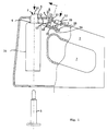
- Figures 1 and 2 show schematically and partially in section a side view of a hand mixer according to the invention in a first and a second operating position.
- the position information is “vertical”, “horizontal”, “above” and “below” refer to the position of the hand mixer shown in FIGS. 1 and 2.
- a hand mixer which consists essentially of a housing 2 and as a passage for the hand of a user serving free space 7. Furthermore contains the housing 2 in its left front section adjustable in the vertical direction Tripping member 14 and in its upper portion that approximately transversely to the direction of adjustment of the trigger member 14 adjustable first switching member 10 and perpendicular to the direction of adjustment of the first switching element 10 adjustable second switching element 12.
- the first switching element 10 is provided to drive a continuous operation of a slow running tool, e.g. a mixer or dough hook on and off.
- a slow running tool e.g. a mixer or dough hook on and off.
- the second switching element 12 is provided to drive a short-time operation of a fast running tool, e.g. a blender on and off.
- the second switching element 12 is designed as a push-button switch which is in the switched-on position must be pressed.
- the outlet member 14 is in Fig. 1 in a lower rest position 1, in the one in the lower part 1 schematically indicated stirring or kneading hook 3 is not inserted.
- the Trigger member 14 has an upper trigger button 11 through a bore 6 of the Surface of the housing 2 protrudes.
- a spring element 9 exerts a bias on the Trigger member 14 down into the rest position I shown in FIG. 1.
- the trigger member 14 is at its upper end with a first locking member 13 Acting projection provided in the adjustment direction of the first switching element 10th is angled.
- the trigger member 14 is coupled to a tool holder in which the stirrer or Kneading hook 3 can be added.
- a tool holder for mounting a blender having a rotating knife is also in the housing 2 available.
- This second tool holder receiving a blender is coaxial or at another point in the housing 2 and possibly also in another axial Position arranged as the tool holder receiving the kneading or stirring hook 3.
- the first switching element 10 is formed in one piece and angularly and is approximately parallel adjustable to the adjacent surface of the housing 2.
- the first switching device 10 has a first leg 21, which is approximately perpendicular to the adjacent surface of the housing 2 is arranged and an actuating part 23 at its free upper end has, which protrudes through an opening 4 in the housing 2 above the surface thereof and serves for manual actuation of the first switching element 10.
- the first leg 21 of the first switching element 10 is perpendicular to a second Leg 22, which is arranged in the adjustment direction of the first switching element 10.
- the first switching element 10 is in a first position A, and the first locking member 13 forming projection of the trigger member 14 rests on the trigger member 14 facing contact surface 18 on the front of the first switching element 10 and blocked thereby the first switching element 10.
- the first position A shown in FIG so that the first switching element 10 are not actuated. Continuous operation of the drive for the slow-running tools cannot be switched on.
- the release button 11 can be actuated to trigger the kneading or stirring hook 3.
- the stirring or Kneading hook 3 can thus not be ejected via the release button 11 in this position B. become.
- the pin 17 of the second associated with the second leg 22 of the first switching element 10 Switching member 12 is located in the position B shown in FIG. 2 of the first switching member 10 on the end face at the free end of the second leg which is designed as a stop surface 28 22 of the first switching element 10, so that the activation of the short-term operation by the second switching element 12 is blocked.
- Fig. 1 and Fig. 2 it can be seen that the trigger button 11 of the trigger member 14, the Actuating part 23 of the first switching element 10 and the push button 29 of the second switching element 12 are arranged immediately adjacent in the upper part of the housing 2, so that these actuators, i.e. the release button 11, the actuating part 23 and the push button 29 can be actuated by a user with the thumb without the Free space 7 gripping hand of the user must change their position on the hand mixer.
- the safety measures described above are in the hand mixer with purely mechanical Measures, i.e. by a simple mechanical design of the release element 14 seated projection 13, the first switching element 10 in connection with the second switching element 12, whose direction of actuation is perpendicular to the adjustment direction of the first switching element 10 is reached.
Landscapes
- Engineering & Computer Science (AREA)
- Mechanical Engineering (AREA)
- Food Science & Technology (AREA)
- Food-Manufacturing Devices (AREA)
- Push-Button Switches (AREA)
- Surgical Instruments (AREA)
- Switches With Compound Operations (AREA)
Applications Claiming Priority (2)
| Application Number | Priority Date | Filing Date | Title |
|---|---|---|---|
| DE19939507A DE19939507A1 (de) | 1999-08-20 | 1999-08-20 | Elektrisch betriebener Handrührer |
| DE19939507 | 1999-08-20 |
Publications (2)
| Publication Number | Publication Date |
|---|---|
| EP1092379A1 true EP1092379A1 (fr) | 2001-04-18 |
| EP1092379B1 EP1092379B1 (fr) | 2003-03-05 |
Family
ID=7919019
Family Applications (1)
| Application Number | Title | Priority Date | Filing Date |
|---|---|---|---|
| EP00116354A Expired - Lifetime EP1092379B1 (fr) | 1999-08-20 | 2000-07-28 | Mixeur à main électrique |
Country Status (5)
| Country | Link |
|---|---|
| US (1) | US6488400B1 (fr) |
| EP (1) | EP1092379B1 (fr) |
| AT (1) | ATE233513T1 (fr) |
| DE (2) | DE19939507A1 (fr) |
| ES (1) | ES2193913T3 (fr) |
Cited By (1)
| Publication number | Priority date | Publication date | Assignee | Title |
|---|---|---|---|---|
| DE102005059697B3 (de) * | 2005-12-14 | 2007-04-19 | Braun Gmbh | Handrührer mit Umschaltung von Kurzzeitbetrieb auf Dauerbetrieb in Abhängigkeit des angekoppelten Arbeitswerkzeugs |
Families Citing this family (15)
| Publication number | Priority date | Publication date | Assignee | Title |
|---|---|---|---|---|
| US7220047B2 (en) * | 2003-07-09 | 2007-05-22 | Conair Corporation | Control dial and ejector button for handheld appliance |
| US7250588B2 (en) | 2005-02-17 | 2007-07-31 | Back To Basics Products, Llc | Combination bread toaster and steamer device |
| FR2889932B1 (fr) * | 2005-08-29 | 2007-11-30 | Electrolux Professionnel Soc P | Appareil electrique de traitement de produits alimentaires dote d'un capteur de vitesse de rotation de l'arbre-moteur. |
| USD534394S1 (en) | 2006-01-09 | 2007-01-02 | Back To Basics Products, Inc. | Blender |
| USD537292S1 (en) | 2006-01-09 | 2007-02-27 | Back To Basics Products, Inc. | Hand mixer |
| USD547601S1 (en) | 2006-06-01 | 2007-07-31 | Back To Basics Products, Inc. | Food processor |
| USD564280S1 (en) | 2006-06-01 | 2008-03-18 | Back To Basics Products, Llc | Coffee maker |
| USD546614S1 (en) | 2006-06-01 | 2007-07-17 | Back To Basics Products, Llc | Toaster and steamer |
| USD543072S1 (en) | 2006-06-01 | 2007-05-22 | Back To Basics Products, Inc. | Blender |
| USD551488S1 (en) | 2006-06-01 | 2007-09-25 | Back To Basics Products, Inc. | Toaster |
| US20110235463A1 (en) * | 2010-03-29 | 2011-09-29 | Domino's Pizza Pmc, Inc. | Mixing apparatus |
| USD769062S1 (en) | 2015-02-18 | 2016-10-18 | Whirlpool Corporation | Immersion blender |
| US10165899B2 (en) | 2015-02-18 | 2019-01-01 | Whirlpool Corporation | Immersion blender |
| USD767934S1 (en) | 2015-02-18 | 2016-10-04 | Whirlpool Corporation | Immersion blender |
| DE202024106045U1 (de) * | 2024-10-21 | 2026-03-26 | De'longhi Braun Household Gmbh | Küchengerät |
Citations (4)
| Publication number | Priority date | Publication date | Assignee | Title |
|---|---|---|---|---|
| US3821902A (en) * | 1965-06-16 | 1974-07-02 | Sunbeam Corp | Electric kitchen appliance |
| DE7902965U1 (de) | 1979-02-03 | 1979-06-28 | Alfred Paul Kg, 7300 Esslingen | Elektrisches handgeraet, wie elektromesser, handruehrer o.dgl. |
| DE2802155A1 (de) * | 1978-01-19 | 1979-07-26 | Brocke Kg I B S | Handmixgeraet |
| EP0529266B1 (fr) | 1991-08-13 | 1994-09-14 | Braun Aktiengesellschaft | Batteur à main électrique |
Family Cites Families (5)
| Publication number | Priority date | Publication date | Assignee | Title |
|---|---|---|---|---|
| US3170674A (en) * | 1960-08-01 | 1965-02-23 | Mc Graw Edison Co | Household mixer |
| FR2730624B1 (fr) * | 1995-02-16 | 1998-06-19 | Moulinex Sa | Batteur-mixeur electrique a main |
| DE29604731U1 (de) * | 1996-03-14 | 1996-06-13 | EGS Elektro- und Hausgerätewerk Suhl GmbH, 98527 Suhl | Einrichtung zur Aktivierung und Entaktivierung der Schalt- und Auswerferfunktion an elektrischen Haushaltsgeräten |
| DE29719596U1 (de) * | 1997-11-04 | 1998-01-15 | Moulinex S.A., Paris | Elektrisches Küchengerät |
| FR2773978B1 (fr) * | 1998-01-23 | 2000-12-22 | Moulinex Sa | Appareil electromenager tenu a la main, en particulier batteur |
-
1999
- 1999-08-20 DE DE19939507A patent/DE19939507A1/de not_active Withdrawn
-
2000
- 2000-07-28 ES ES00116354T patent/ES2193913T3/es not_active Expired - Lifetime
- 2000-07-28 AT AT00116354T patent/ATE233513T1/de not_active IP Right Cessation
- 2000-07-28 DE DE50001369T patent/DE50001369D1/de not_active Expired - Lifetime
- 2000-07-28 EP EP00116354A patent/EP1092379B1/fr not_active Expired - Lifetime
- 2000-08-09 US US09/635,055 patent/US6488400B1/en not_active Expired - Fee Related
Patent Citations (4)
| Publication number | Priority date | Publication date | Assignee | Title |
|---|---|---|---|---|
| US3821902A (en) * | 1965-06-16 | 1974-07-02 | Sunbeam Corp | Electric kitchen appliance |
| DE2802155A1 (de) * | 1978-01-19 | 1979-07-26 | Brocke Kg I B S | Handmixgeraet |
| DE7902965U1 (de) | 1979-02-03 | 1979-06-28 | Alfred Paul Kg, 7300 Esslingen | Elektrisches handgeraet, wie elektromesser, handruehrer o.dgl. |
| EP0529266B1 (fr) | 1991-08-13 | 1994-09-14 | Braun Aktiengesellschaft | Batteur à main électrique |
Cited By (3)
| Publication number | Priority date | Publication date | Assignee | Title |
|---|---|---|---|---|
| DE102005059697B3 (de) * | 2005-12-14 | 2007-04-19 | Braun Gmbh | Handrührer mit Umschaltung von Kurzzeitbetrieb auf Dauerbetrieb in Abhängigkeit des angekoppelten Arbeitswerkzeugs |
| EP1800580A2 (fr) | 2005-12-14 | 2007-06-27 | Braun GmbH | Mélangeur à main commutable entre une durée d'opération courte et longue selon l'outil attaché |
| EP3536204A1 (fr) | 2005-12-14 | 2019-09-11 | Braun GmbH | Mélangeur à main commutable entre une durée d'opération courte et longue selon l'outil attaché |
Also Published As
| Publication number | Publication date |
|---|---|
| US6488400B1 (en) | 2002-12-03 |
| DE19939507A1 (de) | 2001-03-08 |
| ES2193913T3 (es) | 2003-11-16 |
| EP1092379B1 (fr) | 2003-03-05 |
| ATE233513T1 (de) | 2003-03-15 |
| DE50001369D1 (de) | 2003-04-10 |
Similar Documents
| Publication | Publication Date | Title |
|---|---|---|
| EP1092379B1 (fr) | Mixeur à main électrique | |
| DE69900518T2 (de) | Ausverriegelung für Schalter | |
| DE69600634T2 (de) | Elektrisch betriebener handschläger und -rührer | |
| DE19938523A1 (de) | Beweglicher Handgriff für ein angetriebenes Werkzeug | |
| DE2926111A1 (de) | Elektrohandwerkzeug | |
| DE2333508A1 (de) | Wechselschalter zur drehrichtungsumkehr eines elektromotors | |
| DE1552426A1 (de) | Tragbares Arbeitsgeraet,wie ein Bohrgeraet,mit einem umkehrbaren Elektromotor | |
| DE3831344A1 (de) | Elektrohandwerkzeugmaschine mit ausschaltbarer arbeitsstellenbeleuchtung | |
| DE102013221915A1 (de) | Netzbetriebene Handwerkzeugmaschine | |
| DE2629723C3 (de) | Handbetätigbare Einbauschaltvorrichtung für elektrische Maschinen | |
| DE4130174C2 (de) | Elektrowerkzeug, insbesondere Tauchkreissäge mit einer Vorrichtung zum Sichern des Werkzeugwechsels | |
| DE1529273C3 (de) | Elektrisches Vielzweck-Küchengerät | |
| DE2629722A1 (de) | Handbetaetigbare einbauschaltvorrichtung | |
| EP0678268A1 (fr) | Appareil manuel et électrique de traitement d'aliments | |
| DE19958297B4 (de) | Elektrowerkzeug mit verbesserter Schaltervorrichtung | |
| DE2933093A1 (de) | Verstellbarer fahrzeugsitz | |
| DE2802155A1 (de) | Handmixgeraet | |
| DE3341168C2 (fr) | ||
| EP0054912B1 (fr) | Dispositif, en particulier dispositif portatif, pour l'usinage de pièces en forme de tubes et/ou de barres et analogues | |
| EP0197140B1 (fr) | Dispositif de coupe et d'encadrement | |
| EP1800580B1 (fr) | Mélangeur à main commutable entre une durée d'opération courte et longue selon l'outil attaché | |
| DE3247299C2 (de) | Elektrische Schneidevorrichtung für Lebensmittel, insbesondere Elektromesser | |
| AT390726B (de) | Elektrische kuechenmaschine | |
| DE6906246U (de) | Schneidmaschine | |
| DE1908880A1 (de) | Durch einen Ausloeser betaetigte Schaltvorrichtung mit einer Stelleinrichtung fuer die Bewirkung mehrerer bestimmter Stellungen des Ausloesers |
Legal Events
| Date | Code | Title | Description |
|---|---|---|---|
| PUAI | Public reference made under article 153(3) epc to a published international application that has entered the european phase |
Free format text: ORIGINAL CODE: 0009012 |
|
| AK | Designated contracting states |
Kind code of ref document: A1 Designated state(s): AT BE CH CY DE DK ES FI FR GB GR IE IT LI LU MC NL PT SE |
|
| AX | Request for extension of the european patent |
Free format text: AL;LT;LV;MK;RO;SI |
|
| 17P | Request for examination filed |
Effective date: 20010217 |
|
| AKX | Designation fees paid |
Free format text: AT BE CH CY DE DK ES FI FR GB GR IE IT LI LU MC NL PT SE |
|
| GRAH | Despatch of communication of intention to grant a patent |
Free format text: ORIGINAL CODE: EPIDOS IGRA |
|
| GRAH | Despatch of communication of intention to grant a patent |
Free format text: ORIGINAL CODE: EPIDOS IGRA |
|
| GRAA | (expected) grant |
Free format text: ORIGINAL CODE: 0009210 |
|
| AK | Designated contracting states |
Designated state(s): AT BE CH CY DE DK ES FI FR GB GR IE IT LI LU MC NL PT SE |
|
| PG25 | Lapsed in a contracting state [announced via postgrant information from national office to epo] |
Ref country code: IT Free format text: LAPSE BECAUSE OF FAILURE TO SUBMIT A TRANSLATION OF THE DESCRIPTION OR TO PAY THE FEE WITHIN THE PRESCRIBED TIME-LIMIT;WARNING: LAPSES OF ITALIAN PATENTS WITH EFFECTIVE DATE BEFORE 2007 MAY HAVE OCCURRED AT ANY TIME BEFORE 2007. THE CORRECT EFFECTIVE DATE MAY BE DIFFERENT FROM THE ONE RECORDED. Effective date: 20030305 Ref country code: IE Free format text: LAPSE BECAUSE OF FAILURE TO SUBMIT A TRANSLATION OF THE DESCRIPTION OR TO PAY THE FEE WITHIN THE PRESCRIBED TIME-LIMIT Effective date: 20030305 Ref country code: GR Free format text: LAPSE BECAUSE OF FAILURE TO SUBMIT A TRANSLATION OF THE DESCRIPTION OR TO PAY THE FEE WITHIN THE PRESCRIBED TIME-LIMIT Effective date: 20030305 Ref country code: FI Free format text: LAPSE BECAUSE OF FAILURE TO SUBMIT A TRANSLATION OF THE DESCRIPTION OR TO PAY THE FEE WITHIN THE PRESCRIBED TIME-LIMIT Effective date: 20030305 |
|
| REG | Reference to a national code |
Ref country code: GB Ref legal event code: FG4D Free format text: NOT ENGLISH |
|
| REG | Reference to a national code |
Ref country code: CH Ref legal event code: EP Ref country code: CH Ref legal event code: NV Representative=s name: LUCHS & PARTNER PATENTANWAELTE |
|
| GBT | Gb: translation of ep patent filed (gb section 77(6)(a)/1977) |
Effective date: 20030305 |
|
| REG | Reference to a national code |
Ref country code: IE Ref legal event code: FG4D Free format text: GERMAN |
|
| REF | Corresponds to: |
Ref document number: 50001369 Country of ref document: DE Date of ref document: 20030410 Kind code of ref document: P |
|
| PG25 | Lapsed in a contracting state [announced via postgrant information from national office to epo] |
Ref country code: SE Free format text: LAPSE BECAUSE OF FAILURE TO SUBMIT A TRANSLATION OF THE DESCRIPTION OR TO PAY THE FEE WITHIN THE PRESCRIBED TIME-LIMIT Effective date: 20030605 Ref country code: PT Free format text: LAPSE BECAUSE OF FAILURE TO SUBMIT A TRANSLATION OF THE DESCRIPTION OR TO PAY THE FEE WITHIN THE PRESCRIBED TIME-LIMIT Effective date: 20030605 Ref country code: DK Free format text: LAPSE BECAUSE OF FAILURE TO SUBMIT A TRANSLATION OF THE DESCRIPTION OR TO PAY THE FEE WITHIN THE PRESCRIBED TIME-LIMIT Effective date: 20030605 |
|
| PGFP | Annual fee paid to national office [announced via postgrant information from national office to epo] |
Ref country code: ES Payment date: 20030704 Year of fee payment: 4 |
|
| PGFP | Annual fee paid to national office [announced via postgrant information from national office to epo] |
Ref country code: BE Payment date: 20030724 Year of fee payment: 4 |
|
| PG25 | Lapsed in a contracting state [announced via postgrant information from national office to epo] |
Ref country code: LU Free format text: LAPSE BECAUSE OF NON-PAYMENT OF DUE FEES Effective date: 20030728 Ref country code: CY Free format text: LAPSE BECAUSE OF FAILURE TO SUBMIT A TRANSLATION OF THE DESCRIPTION OR TO PAY THE FEE WITHIN THE PRESCRIBED TIME-LIMIT Effective date: 20030728 |
|
| PGFP | Annual fee paid to national office [announced via postgrant information from national office to epo] |
Ref country code: AT Payment date: 20030729 Year of fee payment: 4 |
|
| PG25 | Lapsed in a contracting state [announced via postgrant information from national office to epo] |
Ref country code: MC Free format text: LAPSE BECAUSE OF NON-PAYMENT OF DUE FEES Effective date: 20030731 |
|
| REG | Reference to a national code |
Ref country code: IE Ref legal event code: FD4D Ref document number: 1092379E Country of ref document: IE |
|
| REG | Reference to a national code |
Ref country code: ES Ref legal event code: FG2A Ref document number: 2193913 Country of ref document: ES Kind code of ref document: T3 |
|
| ET | Fr: translation filed | ||
| PLBE | No opposition filed within time limit |
Free format text: ORIGINAL CODE: 0009261 |
|
| STAA | Information on the status of an ep patent application or granted ep patent |
Free format text: STATUS: NO OPPOSITION FILED WITHIN TIME LIMIT |
|
| 26N | No opposition filed |
Effective date: 20031208 |
|
| PGFP | Annual fee paid to national office [announced via postgrant information from national office to epo] |
Ref country code: GB Payment date: 20040621 Year of fee payment: 5 |
|
| PGFP | Annual fee paid to national office [announced via postgrant information from national office to epo] |
Ref country code: FR Payment date: 20040721 Year of fee payment: 5 |
|
| PG25 | Lapsed in a contracting state [announced via postgrant information from national office to epo] |
Ref country code: AT Free format text: LAPSE BECAUSE OF NON-PAYMENT OF DUE FEES Effective date: 20040728 |
|
| PG25 | Lapsed in a contracting state [announced via postgrant information from national office to epo] |
Ref country code: ES Free format text: LAPSE BECAUSE OF NON-PAYMENT OF DUE FEES Effective date: 20040729 |
|
| PG25 | Lapsed in a contracting state [announced via postgrant information from national office to epo] |
Ref country code: LI Free format text: LAPSE BECAUSE OF NON-PAYMENT OF DUE FEES Effective date: 20040731 Ref country code: CH Free format text: LAPSE BECAUSE OF NON-PAYMENT OF DUE FEES Effective date: 20040731 Ref country code: BE Free format text: LAPSE BECAUSE OF NON-PAYMENT OF DUE FEES Effective date: 20040731 |
|
| BERE | Be: lapsed |
Owner name: *BRAUN G.M.B.H. Effective date: 20040731 |
|
| PG25 | Lapsed in a contracting state [announced via postgrant information from national office to epo] |
Ref country code: NL Free format text: LAPSE BECAUSE OF NON-PAYMENT OF DUE FEES Effective date: 20050201 |
|
| REG | Reference to a national code |
Ref country code: CH Ref legal event code: PL |
|
| NLV4 | Nl: lapsed or anulled due to non-payment of the annual fee |
Effective date: 20050201 |
|
| PG25 | Lapsed in a contracting state [announced via postgrant information from national office to epo] |
Ref country code: GB Free format text: LAPSE BECAUSE OF NON-PAYMENT OF DUE FEES Effective date: 20050728 |
|
| REG | Reference to a national code |
Ref country code: ES Ref legal event code: FD2A Effective date: 20040729 |
|
| GBPC | Gb: european patent ceased through non-payment of renewal fee |
Effective date: 20050728 |
|
| PG25 | Lapsed in a contracting state [announced via postgrant information from national office to epo] |
Ref country code: FR Free format text: LAPSE BECAUSE OF NON-PAYMENT OF DUE FEES Effective date: 20060331 |
|
| REG | Reference to a national code |
Ref country code: FR Ref legal event code: ST Effective date: 20060331 |
|
| BERE | Be: lapsed |
Owner name: *BRAUN G.M.B.H. Effective date: 20040731 |
|
| PGFP | Annual fee paid to national office [announced via postgrant information from national office to epo] |
Ref country code: DE Payment date: 20160801 Year of fee payment: 17 |
|
| REG | Reference to a national code |
Ref country code: DE Ref legal event code: R119 Ref document number: 50001369 Country of ref document: DE |
|
| PG25 | Lapsed in a contracting state [announced via postgrant information from national office to epo] |
Ref country code: DE Free format text: LAPSE BECAUSE OF NON-PAYMENT OF DUE FEES Effective date: 20180201 |