EP1092442B1 - Herstellungsmethode einer Spritze mit einziehbarer Nadel - Google Patents
Herstellungsmethode einer Spritze mit einziehbarer Nadel Download PDFInfo
- Publication number
- EP1092442B1 EP1092442B1 EP00117086A EP00117086A EP1092442B1 EP 1092442 B1 EP1092442 B1 EP 1092442B1 EP 00117086 A EP00117086 A EP 00117086A EP 00117086 A EP00117086 A EP 00117086A EP 1092442 B1 EP1092442 B1 EP 1092442B1
- Authority
- EP
- European Patent Office
- Prior art keywords
- needle
- distal end
- hub
- needle assembly
- plunger
- Prior art date
- Legal status (The legal status is an assumption and is not a legal conclusion. Google has not performed a legal analysis and makes no representation as to the accuracy of the status listed.)
- Expired - Lifetime
Links
- 238000004519 manufacturing process Methods 0.000 title claims description 14
- 238000000034 method Methods 0.000 claims description 21
- 239000000853 adhesive Substances 0.000 claims description 8
- 230000001070 adhesive effect Effects 0.000 claims description 8
- 230000033001 locomotion Effects 0.000 claims description 5
- 230000001954 sterilising effect Effects 0.000 claims description 5
- 238000005520 cutting process Methods 0.000 claims description 4
- 230000006835 compression Effects 0.000 claims description 3
- 238000007906 compression Methods 0.000 claims description 3
- 238000007789 sealing Methods 0.000 claims 1
- 239000003814 drug Substances 0.000 description 15
- 229940079593 drug Drugs 0.000 description 15
- 238000013461 design Methods 0.000 description 9
- 238000002347 injection Methods 0.000 description 7
- 239000007924 injection Substances 0.000 description 7
- 230000008569 process Effects 0.000 description 7
- 230000000712 assembly Effects 0.000 description 5
- 238000000429 assembly Methods 0.000 description 5
- 239000007788 liquid Substances 0.000 description 5
- 238000013459 approach Methods 0.000 description 3
- 230000008901 benefit Effects 0.000 description 3
- 238000009434 installation Methods 0.000 description 3
- 230000009471 action Effects 0.000 description 2
- 230000004888 barrier function Effects 0.000 description 2
- 230000006378 damage Effects 0.000 description 2
- 230000006872 improvement Effects 0.000 description 2
- 239000000463 material Substances 0.000 description 2
- 238000002483 medication Methods 0.000 description 2
- 230000000813 microbial effect Effects 0.000 description 2
- 239000004033 plastic Substances 0.000 description 2
- 230000005855 radiation Effects 0.000 description 2
- 238000004659 sterilization and disinfection Methods 0.000 description 2
- 238000003466 welding Methods 0.000 description 2
- 244000043261 Hevea brasiliensis Species 0.000 description 1
- 208000027418 Wounds and injury Diseases 0.000 description 1
- 239000000969 carrier Substances 0.000 description 1
- 238000004891 communication Methods 0.000 description 1
- 238000011109 contamination Methods 0.000 description 1
- 238000002788 crimping Methods 0.000 description 1
- 230000007812 deficiency Effects 0.000 description 1
- 230000006735 deficit Effects 0.000 description 1
- 201000010099 disease Diseases 0.000 description 1
- 208000037265 diseases, disorders, signs and symptoms Diseases 0.000 description 1
- 229920001971 elastomer Polymers 0.000 description 1
- 239000013536 elastomeric material Substances 0.000 description 1
- 229920006332 epoxy adhesive Polymers 0.000 description 1
- 239000012530 fluid Substances 0.000 description 1
- 230000036541 health Effects 0.000 description 1
- 208000015181 infectious disease Diseases 0.000 description 1
- 208000014674 injury Diseases 0.000 description 1
- 230000001788 irregular Effects 0.000 description 1
- 230000002427 irreversible effect Effects 0.000 description 1
- 239000002184 metal Substances 0.000 description 1
- 238000000465 moulding Methods 0.000 description 1
- 229920003052 natural elastomer Polymers 0.000 description 1
- 229920001194 natural rubber Polymers 0.000 description 1
- 239000005060 rubber Substances 0.000 description 1
- 238000000926 separation method Methods 0.000 description 1
- 229920003051 synthetic elastomer Polymers 0.000 description 1
- 239000005061 synthetic rubber Substances 0.000 description 1
- 229920002725 thermoplastic elastomer Polymers 0.000 description 1
- 238000012549 training Methods 0.000 description 1
- 238000012546 transfer Methods 0.000 description 1
Images


Classifications
-
- A—HUMAN NECESSITIES
- A61—MEDICAL OR VETERINARY SCIENCE; HYGIENE
- A61M—DEVICES FOR INTRODUCING MEDIA INTO, OR ONTO, THE BODY; DEVICES FOR TRANSDUCING BODY MEDIA OR FOR TAKING MEDIA FROM THE BODY; DEVICES FOR PRODUCING OR ENDING SLEEP OR STUPOR
- A61M5/00—Devices for bringing media into the body in a subcutaneous, intra-vascular or intramuscular way; Accessories therefor, e.g. filling or cleaning devices, arm-rests
- A61M5/178—Syringes
- A61M5/31—Details
- A61M5/32—Needles; Details of needles pertaining to their connection with syringe or hub; Accessories for bringing the needle into, or holding the needle on, the body; Devices for protection of needles
- A61M5/3205—Apparatus for removing or disposing of used needles or syringes, e.g. containers; Means for protection against accidental injuries from used needles
- A61M5/321—Means for protection against accidental injuries by used needles
- A61M5/322—Retractable needles, i.e. disconnected from and withdrawn into the syringe barrel by the piston
- A61M5/3234—Fully automatic needle retraction, i.e. in which triggering of the needle does not require a deliberate action by the user
-
- A—HUMAN NECESSITIES
- A61—MEDICAL OR VETERINARY SCIENCE; HYGIENE
- A61M—DEVICES FOR INTRODUCING MEDIA INTO, OR ONTO, THE BODY; DEVICES FOR TRANSDUCING BODY MEDIA OR FOR TAKING MEDIA FROM THE BODY; DEVICES FOR PRODUCING OR ENDING SLEEP OR STUPOR
- A61M5/00—Devices for bringing media into the body in a subcutaneous, intra-vascular or intramuscular way; Accessories therefor, e.g. filling or cleaning devices, arm-rests
- A61M5/002—Packages specially adapted therefor, e.g. for syringes or needles, kits for diabetics
-
- A—HUMAN NECESSITIES
- A61—MEDICAL OR VETERINARY SCIENCE; HYGIENE
- A61M—DEVICES FOR INTRODUCING MEDIA INTO, OR ONTO, THE BODY; DEVICES FOR TRANSDUCING BODY MEDIA OR FOR TAKING MEDIA FROM THE BODY; DEVICES FOR PRODUCING OR ENDING SLEEP OR STUPOR
- A61M5/00—Devices for bringing media into the body in a subcutaneous, intra-vascular or intramuscular way; Accessories therefor, e.g. filling or cleaning devices, arm-rests
- A61M5/178—Syringes
- A61M5/31—Details
- A61M5/32—Needles; Details of needles pertaining to their connection with syringe or hub; Accessories for bringing the needle into, or holding the needle on, the body; Devices for protection of needles
- A61M5/3202—Devices for protection of the needle before use, e.g. caps
-
- A—HUMAN NECESSITIES
- A61—MEDICAL OR VETERINARY SCIENCE; HYGIENE
- A61M—DEVICES FOR INTRODUCING MEDIA INTO, OR ONTO, THE BODY; DEVICES FOR TRANSDUCING BODY MEDIA OR FOR TAKING MEDIA FROM THE BODY; DEVICES FOR PRODUCING OR ENDING SLEEP OR STUPOR
- A61M5/00—Devices for bringing media into the body in a subcutaneous, intra-vascular or intramuscular way; Accessories therefor, e.g. filling or cleaning devices, arm-rests
- A61M5/178—Syringes
- A61M5/31—Details
- A61M5/32—Needles; Details of needles pertaining to their connection with syringe or hub; Accessories for bringing the needle into, or holding the needle on, the body; Devices for protection of needles
- A61M5/34—Constructions for connecting the needle, e.g. to syringe nozzle or needle hub
- A61M5/349—Constructions for connecting the needle, e.g. to syringe nozzle or needle hub using adhesive bond or glues
-
- A—HUMAN NECESSITIES
- A61—MEDICAL OR VETERINARY SCIENCE; HYGIENE
- A61M—DEVICES FOR INTRODUCING MEDIA INTO, OR ONTO, THE BODY; DEVICES FOR TRANSDUCING BODY MEDIA OR FOR TAKING MEDIA FROM THE BODY; DEVICES FOR PRODUCING OR ENDING SLEEP OR STUPOR
- A61M5/00—Devices for bringing media into the body in a subcutaneous, intra-vascular or intramuscular way; Accessories therefor, e.g. filling or cleaning devices, arm-rests
- A61M5/50—Devices for bringing media into the body in a subcutaneous, intra-vascular or intramuscular way; Accessories therefor, e.g. filling or cleaning devices, arm-rests having means for preventing re-use, or for indicating if defective, used, tampered with or unsterile
- A61M5/5013—Means for blocking the piston or the fluid passageway to prevent illegal refilling of a syringe
- A61M5/502—Means for blocking the piston or the fluid passageway to prevent illegal refilling of a syringe for blocking the piston
-
- A—HUMAN NECESSITIES
- A61—MEDICAL OR VETERINARY SCIENCE; HYGIENE
- A61M—DEVICES FOR INTRODUCING MEDIA INTO, OR ONTO, THE BODY; DEVICES FOR TRANSDUCING BODY MEDIA OR FOR TAKING MEDIA FROM THE BODY; DEVICES FOR PRODUCING OR ENDING SLEEP OR STUPOR
- A61M5/00—Devices for bringing media into the body in a subcutaneous, intra-vascular or intramuscular way; Accessories therefor, e.g. filling or cleaning devices, arm-rests
- A61M5/50—Devices for bringing media into the body in a subcutaneous, intra-vascular or intramuscular way; Accessories therefor, e.g. filling or cleaning devices, arm-rests having means for preventing re-use, or for indicating if defective, used, tampered with or unsterile
- A61M5/508—Means for preventing re-use by disrupting the piston seal, e.g. by puncturing
Definitions
- the present invention relates to syringes and needle assemblies. More particularly, the present invention relates to a syringe and needle assembly having structure allowing for the automatic withdrawal of the needle cannula into the syringe barrel after use and a method for making the needle assembly.
- a safety device contained within the syringe or needle assembly is activated to prevent further contact with the sharp needle tip.
- One type of safety syringe includes structure which allows the withdrawal of the hypodermic needle into the syringe barrel to minimize the chance of further contact with the sharp needle tip.
- One such prior art retractable needle syringe includes a frangible zone which allows the separation of the forward wall of the barrel, which is connected to the hypodermic needle, from the sidewall of the barrel.
- the syringe also contains structure on the interior of the forward wall and the exterior of the piston for selectively attaching the piston to the forward wall so that the user can forcibly twist the piston to break the frangible structure and draw the forward wall, including the hypodermic needle, into the syringe barrel.
- This design requires a compromise in the design of the syringe barrel.
- the barrel must be strong enough to remain intact during normal use yet weak enough to be sheared apart by any user regardless of strength.
- the prior art also includes other retractable needle syringes. These syringes have structure that engages a needle carrier allowing the needle carrier to be forcibly disengaged from the syringe barrel, by action of the plunger rod, and withdrawn into the syringe barrel.
- Many prior art retractable needle syringes have deficiencies similar to that described above.
- the needle or the needle carrier of the retractable needle syringe must be securely held by the syringe barrel during normal use which often includes substantial hydraulic pressures experienced during injection, especially with highly viscous liquids, and forces including piercing rubber stoppers of medication vials.
- the syringe barrel must hold the needle carrier to a degree that it will not be overcome by the forces of normal use and will still be disengageable through forces applied to a plunger rod which extends from the open proximal end of the syringe barrel.
- Many prior art retractable needle syringe designs when made with sufficient strength to withstand the forces of normal use have a needle carrier which cannot be easily disengaged.
- easy disengagement of the needle or the needle carrier can lead to a structure which may not withstand the forces of normal use. This is especially true with needle carriers which are structured to allow a needle assembly to be installed and removed so that the user can select the hypodermic needle size at the time of use.
- These syringes must also resist the high torque and forces of needle installation and removal.
- retractable needle syringes require a two-handed withdrawal procedure which increases the difficulty of use.
- the prior art also includes retracting needle syringes which include a spring loaded needle assembly which is held in position during normal use of the syringe assembly and a hollow plunger rod which is sealed during normal use of the syringe assembly so that medication may not enter the plunger rod cavity.
- retracting needle syringes must have structure to allow release of the spring-loaded needle and the opening of the plunger rod cavity so that the needle may enter the plunger rod cavity after the syringe is used for its intended purpose.
- the retracting needle syringes have similar design problems as those recited hereinabove for retractable needle syringes. In particular, the cavity in the plunger rod must be sealed so that medication cannot enter the plunger rod during use.
- This seal must sometimes withstand high hydraulic pressures when injecting relatively viscous medication through small needles and still be capable of being easily unsealed and to allow access by the needle assembly.
- the needle assembly must be firmly held in place through the forces of injection and still be disengageable so that it may retract into the syringe barrel and into the plunger rod.
- US Patent 5,961,491 describes a non-reusable retractable safety syringe having a hollow plunger and a seal member thereon.
- a hollow needle is mounted to the syringe having a biasing means.
- a cutting portion of the plunger cuts through the seal member, to allow the biasing means to carry the needle into the plunger.
- US Patent 5,180,369 describes a further retractable safety syringe having a needle cannula fixed to a slidable piston.
- the syringe includes a hollow plunger having a shatter plate over one end; when pressure is exerted on the piston the shatter plate shatters, allowing a slidable piston on which the needle cannula is mounted to be retracted into the plunger.
- the slidable piston of this device is mounted indirectly to the needle cannula via an intermediary first barrel.
- the present invention provides a method of making an operable retracting needle assembly comprising the steps of: providing an outer hub having a proximal end, a distal end and a passageway therethrough, providing an inner hub having a proximal end, a distal end and a conduit therethrough, said proximal end having an inner portion and a dissociable outer portion connected to the said inner portion; providing a needle cannula having a distal end, a proximal end and a lumen therethrough; providing a coil compression spring; assembling the inner hub, the spring and outer hub so that said inner hub (61) is directly connected to said outer hub (53) and so that the spring is compressed and held between the inner hub and the outer hub by the inner hub being connected to the outer hub so that the distal end of the inner hub is accessible from the passage way at the distal end of the outer hub; positioning the proximal end of the cannula in the distal end of the conduit of the inner hub; and applying adhesive in the space between the conduit and the needle can
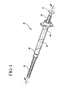
- an operable retracting needle syringe 20 includes a retracting needle assembly 21, a syringe barrel 22 and a plunger 23.
- the barrel includes an inside surface 25 defining a chamber 27, an open proximal end 28 and an open distal end 29 including a cylindrical collar 31 having an outside surface 32 and an inside surface 33.
- the plunger is slidably positioned in fluid-tight engagement with the inside surface of the barrel.
- the plunger includes a proximal portion 37 having a distal end 38 with an elongated cavity 39 therein.
- a release element 43 having a sharp distal edge 44 is positioned at distal end 38 of the proximal portion of plunger 23.
- a hollow distal portion 46 of plunger 23 is releasably connected to proximal portion 37 and capable of telescopic motion with respect to the proximal portion.
- a cover element on the distal portion seals a distal end 47. In this embodiment the cover element is stopper 50. It is preferred that the cover element be made of an elastomeric material selected from the group of thermoplastic elastomers, natural rubber, synthetic rubber and combinations thereof.
- Retracting needle assembly 21 includes an outer hub 53 having a proximal end 55, a distal end 56 and a passageway 57 therethrough.
- the retracting needle assembly also includes an inner hub 61 having a proximal end 62, a distal end 63 and a conduit therethrough 64.
- the inner hub includes an inner portion 65 and a dissociable outer portion 67 connected to the inner portion.
- the dissociable outer portion is connected to outer hub 53.
- Distal end 63 of the inner hub is smaller than passageway 57 of the outer hub at distal end 56 and is accessible therefrom and preferably projects distally outwardly therefrom.
- a needle cannula 71 having a distal end 73, a proximal end 74 and a lumen 75 therethrough.
- the proximal end of the cannula is connected to distal end 63 of the inner hub so that the lumen is in fluid communication with conduit 64 of the inner hub.
- the distal end of the cannula preferably includes a sharp or sharpened distal tip.
- An energized spring is contained between the outer and inner hubs and this preferred embodiment the energized spring is a compressed coil spring 76.
- Various spring types and elastomeric materials and the like can be used to provide a biasing force between the inner and outer hubs with the coil spring being merely representative of these many possibilities all of which are within the purview of the present invention.
- a coil spring is preferred because of its compact size and the ability to easily design the spring to provide the forces necessary for proper operation of the retractable needle assembly.
- the coil spring is placed over the inner portion of the inner hub and then the distal end of the spring is positioned in the outer hub and the inner and outer hubs are moved toward each other to compress the spring and lock together through the action of annular locking projection 70 on the inner hub and annular locking recess 59 in the outer hub.
- annular locking projection on the inner hub snaps into annular locking recess 59 in the outer hub.
- the projection and the recess are shaped so that much less force is required to assemble the components than to reverse the process, thus providing for a permanent locked condition wherein the inner hub and the outer hub are inseparable during normal operating conditions.
- the retracting needle assembly also includes means for connecting the outer hub to the collar of the syringe barrel.
- means for connecting includes structure providing for threadable engagement between the collar and the outer hub.
- the structure for threadable engagement may include at least one thread 58 in passageway 57 of outer hub 53 and at least one thread 34 on outside surface 32 of the cylindrical collar.
- the ability to provide a needle assembly which is removably connected to the barrel is an important feature. This feature allows flexibility to interchange needle assemblies and syringes to obtain an appropriately sized needle and syringe combination for the desired drug type and injection site.
- the structure allows the installation and removal of the needle assembly from the barrel using the same motions required for installation and removal of a standard hypodermic needle from a standard hypodermic syringe so that no additional training is required for the health care worker.
- retracting needle syringe with low dead space. This means that almost all of the medication in the chamber is expelled from the syringe during the injection process.
- Many prior art retractable and retracting needle syringes have structure protruding into the chamber for holding and/or releasing the retracting or retractable needle. Much of the medication surrounding these structures is lost and will not be delivered because needle retraction will have begun while the medication is still in the barrel.
- the user could begin the needle retracting process while the needle is still within the patient. The needle could still come out of the patient while medication is being delivered and there is a potential for injury to the patient if the needle is moved laterally as the result of the force being applied to initiate the needle retraction process.
- the preferred embodiment includes a frusto-conically shaped surface 68 at proximal end 62 of the inner hub which is preferably a recess. This surface is adapted to mate a conically-shaped surface 51 on stopper 50. Surface 51 is preferably a projection.
- the distal end of the syringe barrel includes a frusto-conically shaped surface 30 which also approaches and preferably touches the stopper when the plunger is in its distal-most position with respect to delivering medication from the chamber.
- the structure for threadable engagement between the collar and the outer hub can include a wide variety of thread-like and bayonette-type structures including a thread on the outside surface of the collar and a thread follower projection on the inside surface of the outer hub which will follow the collar thread as the hub is screwed onto the collar.
- This structure is similar to the well-known locking luer-type needle assembly and syringe combinations wherein the syringe collar has a thread on its inside surface and the needle assembly has two outwardly directed projections on the base of its hub for allowing the hub follow the threads of the collar as it is screwed onto the luer tip and collar.
- the inside of the collar can be threaded in the outside of the outer hub can have thread followers.
- the preferred embodiment includes tapered cylindrical surface 69 on inner hub 61 and tapered cylindrical surface 35 on the inside of cylindrical collar 31 of the barrel.
- the tapered cylindrical surface 35 on the collar engages tapered cylindrical surface 69 on the inner hub to seal the interface between the hub and the collar to prevent leakage during normal use.
- Retracting needle assembly 21 preferably, but not necessarily, includes an elongated needle shield 79 having an open proximal end 80, a distal end 81 and a sidewall 82 therebetween defining a recess 83 in the shield.
- the shield removably engages the outer hub and covers the needle cannula.
- the shield helps protect the needle cannula from contamination before use.
- the shield preferably frictionally engages portions of outer hub 53.
- the retracting needle assembly can be removably connected to syringe barrel 22 containing plunger 23. Needle shield 79 can now be removed from the retracting needle assembly thus exposing the needle cannula for use.
- the retracting needle syringe can be filled using known methods such as withdrawing injectable liquid from a vial having a pierceable stopper. A syringe may then be used to inject liquid into a patient, an I.V. set, a catheter or other suitable device. After the liquid in the chamber is injected or otherwise delivered, the distal end of the stopper will be contacting the distal end of the barrel chamber as best illustrated in Fig. 9.
- the user can apply additional distally directed axial force to the proximal end of the plunger to bottom out the stopper on the distal end of the barrel chamber and to cause the disengagement of the proximal portion 37 of the plunger from distal portion 46 of the plunger. Because the connection between the proximal portion of the plunger and the distal portion of the plunger is broken or overcome, the proximal portion will move distally within the distal portion and along the barrel advancing release element 43 so that its sharp distal end will press on and cut through stopper 50 and through the inner hub between inner portion 65 and dissociable outer portion 67, as best illustrated in Fig. 10.
- Another feature of the syringe barrel and plunger is proximally facing circular wall 40 on the proximal end of the barrel which is slightly larger than flange 41 on the proximal end of the plunger so that when the plunger reaches its furthest distal position with respect to the barrel, the flange 41 is within the circular wall 40 thus preventing the user from attempting to pull the plunger in a proximal direction in an attempt to re-expose the needle.
- a mechanical interference such as an overlap or snap fit structure can also be provided to further hold the flange inside the circular wall.
- inwardly directed ledge 45 is provided to hold the plunger in the barrel after the needle cannula has been retracted.
- a second groove 48 on the plunger rod can be used to help hold the plunger in the barrel after needle retraction.
- This second groove is preferably used if an inwardly directed ledge or other structure is not used on circular wall 40.
- annular projection 49 on the plunger will engage groove 48 after needle retraction. This engagement will hold the proximal portion of the plunger to the distal portion of the plunger, wherein the distal portion of the plunger will be held in the barrel by the friction of the stopper.
- the releasable connection between proximal portion 37 of the plunger and distal portion 46 of the plunger which allows the telescopic relative motion between the two plunger portions is provided by a snap-fit arrangement between the proximal portion of the plunger and the distal portion of the plunger.
- an annular projection 49 on the inside of the proximal end of the distal portion 46 of the plunger engages an annular groove 42 on the proximal end of proximal portion 37 of the plunger.
- annular projection 49 disengages from annular groove 42 allowing the distal end of the release element to cut through the stopper and the inner hub between the dissociable outer portion and the inner portion.
- connection can also be breakable as well as disengageable such as by use of a frangible adhesive between the two elements or molding the elements as an integral structure containing a brittle plastic projection or projections which join the elements and can be broken with a force applied to the plunger.
- a breakable connection can also be made by connecting the elements with a sheer pin.
- a sheer pin made be made of plastic with one or more notches or stress risers suitably placed to cause breaking at the desired force levels.
- a breakable connection may also be accomplished similar to the snap fit arrangement but designing the various projections and recesses to fail upon reaching the desired stress level.
- Fig. 12 illustrates an alternative embodiment which functions similarly to the embodiment of Figs. 1-11 except that means for connecting the outer hub to the collar.
- syringe barrel 122 includes an inside surface 125 defining a chamber 127, an open distal end 129, an open proximal end (not shown) and a cylindrical collar 131.
- the cylindrical collar includes an outside surface 132 and an inside surface 133.
- the inside surface includes at least one thread 134.
- a retracting needle assembly 121 includes an outer hub 153 having at least one, and in this preferred embodiment two radially directed outwardly projecting tabs sized and shaped to engage thread 134 so that the retracting needle assembly can be releasably engaged with the syringe barrel through rotational motion of the needle assembly relative to the barrel.
- the outer hub can be attached to the collar using adhesive or ultrasonic welding, retaining clips or a one-way snap-fit arrangement that renders the assembly irreversible under normal use.
- Such structures fall within the purview of the prevent invention.
- the present invention is a method of making an operable retracting needle assembly.
- Many prior art retracting needle syringes have a major deficit in that their manufacture requires the needle to be assembled to the needle hub first and then the needle assembly including the needle and the hub is joined with the spring and outer hub or similar structures by placing the spring over the needle and the outer hub over the sharp tip of the needle.
- This is a difficult task and nearly impossible under high volume manufacturing since the potential for damaging the fragile sharpened distal end of the needle cannula is great. Consequently, these designs may become prohibitively expensive to make under mass production circumstances or yield an unacceptable level of damaged needles which are unsuitable for their purpose or at the very least very painful to the patient.
- a major improvement provided by the present invention is overcoming the aforementioned shortcomings of prior art retractable needle syringes and retractable needles.
- the present invention allows the assembly of the inner and outer hub and the spring before the addition and connection of the sharpened needle cannula. This allows the retracting needle assembly of the present invention to be manufactured in a similar manner to conventional needle assemblies wherein the needle is attached to the finished hub after which there are no further assembly steps but for the application of a needle shield.
- the method of making an operable retracting needle assembly 221 comprises the steps of: providing an outer hub 253 having a proximal end 255, a distal end 256 and a passageway 257 therethrough; providing an inner hub 261 having a proximal end 262, a distal end 263 and a conduit therethrough; providing a needle cannula 271 having a distal end 273, a proximal end 274 and a lumen therethrough; providing a coil compression spring 276; assembling the inner hub, the spring and the outer hub so that the spring is compressed and held within the outer hub by the inner hub being connected to the outer hub so that the distal end of the inner hub is accessible from the passageway at the distal end of the outer hub; position proximal end 274 of cannula 271, (as best illustrated in Fig.
- adhesives are suitable for attaching a cannula to a hub including epoxy adhesives which may be self-curing or curable with heat, ultraviolet light and the like.
- the method of making an operable retracting needle assembly preferably further includes providing an elongated needle shield 279 and removably connecting the needle shield to outer hub 253 so that the distal end of the needle cannula is in the needle shield.
- the retracting needle assembly may be sealed in a package 288 which functions as a microbial barrier and sterilized along with the package using a method such as radiation sterilization, autodaving or the like.
- the method of making a retracting needle assembly preferably also includes attaching the needle assembly to a syringe barrel 22 (see Figs. 1-11) having an inside surface 25 defining a chamber 27, an open proximal end 28 and open distal end 29 including a cylindrical collar 31 so that outer hub 253 engages collar 31.
- the method may further include providing a plunger 23 either before or after the retracting needle assembly is attached to the syringe barrel.
- this step occurs first before the attachment of the retracting needle assembly.
- This step includes providing a plunger 23 slidably positioned in fluid-tight engagement with the inside surface of said syringe barrel.
- the retracting needle syringe may be sealed in a package 289 which function as a microbial barrier and the package along with the retracting needle syringe is sterilized using a method such as radiation sterilization, autoclaving or the like.
- the present invention offers a major advantage over the prior art by allowing the needle cannula to be assembled to the retracting needle assembly after the components of the needle assembly have been assembled thereby greatly reducing any potential for damaging the fragile needle tip during the assembly process.
Landscapes
- Health & Medical Sciences (AREA)
- Engineering & Computer Science (AREA)
- Heart & Thoracic Surgery (AREA)
- Vascular Medicine (AREA)
- Anesthesiology (AREA)
- Biomedical Technology (AREA)
- Environmental & Geological Engineering (AREA)
- Hematology (AREA)
- Life Sciences & Earth Sciences (AREA)
- Animal Behavior & Ethology (AREA)
- General Health & Medical Sciences (AREA)
- Public Health (AREA)
- Veterinary Medicine (AREA)
- Infusion, Injection, And Reservoir Apparatuses (AREA)
Claims (10)
- Verfahren zur Herstellung einer funktionfähigen sich zurückziehenden Nadelbaugruppe (21), das die folgenden Schritte aufweist:Bereitstellen einer äußeren Nabe (23) mit einem proximalen Ende (55), einem distalen Ende (56) und einem Durchgang (57) dort hindurch;Bereitstellen einer inneren Nabe (61) mit einem proximalen Ende (62), einem distalen Ende (63) und einem Kanal (64) dort hindurch, wobei das proximale Ende einen inneren Abschnitt (65) und einen mit dem inneren Abschnitt verbundenen trennbaren äußeren Abschnitt (67) aufweit;Bereitstellen einer Nadelkanüle (71) mit einem distalen Ende (73), einem proximalen Ende (74) und einem Hohlraum (75) dort hindurch;Bereitstellen einer Schraubendruckfeder (76);Zusammenbauen der inneren Nabe (61), der Feder (76) und der äußeren Nabe (53) so, daß die innere Nabe (61) direkt mit der äußeren Nabe (53) ausgerichtet ist, und so, daß die Feder zusammengedrückt und zwischen der inneren Nabe und der äußeren Nabe dadurch gehalten wird, daß die innere Nabe mit der äußeren Nabe verbunden ist, so daß das distale Ende (63) der inneren Nabe vom Durchgang (57) am distalen Ende der äußeren Nabe zugänglich ist;Positionieren des proximalen Endes (74) der Kanüle (71) im distalen Ende (63) des Kanals der inneren Nabe; undAufbringen von Klebstoff im Raum zwischen dem Kanal (64) und der Nadelkanüle (71).
- Verfahren zur Herstellung einer Nadelbaugruppe nach Anspruch 1, das außerdem den Schritt des entfernbaren Verbindens einer länglichen Nadelhülse (79) mit der äußeren Nabe aufweist, so daß das distale Ende der Nadelkanüle in der Nadelhülse ist.
- Verfahren nach Anspruch 2, das außerdem die Schritte des Anordnens der Nadelbaugruppe in einer Verpackung (289) und des Sterilisierens der Nadelbaugruppe und der Verpackung aufweist.
- Verfahren zur Herstellung einer Nadelbaugruppe nach Anspruch 2, das außerdem den Schritt des Befestigens der Nadelbaugruppe an einem Spritzenzylinder (22) mit einer Innenfläche aufweist, die eine Kammer definiert, wobei ein offenes proximales Ende und ein offenes distales Ende einen zylindrischen Ring umfassen, so daß die äußere Nabe mit dem Ring in Eingriff kommt.
- Verfahren zur Herstellung einer Nadelbaugruppe nach Anspruch 4, bei dem der Spritzenzylinder (22) einen Kolben (23) umfaßt, der verschiebbar in einem fluiddichten Eingriff mit der Innenfläche des Spritzenzylinders positioniert ist, wobei der Kolben außerdem ein Freigabeelement (43) mit einem scharfen distalen Ende umfaßt, das durch die innere Nabe schneiden kann, um den trennbaren äußeren Abschnitt (67) vom inneren Abschnitt (65) der inneren Nabe zu trennen.
- Verfahren nach Anspruch 5, das außerdem die Schritte des Anordnens der Nadelbaugruppe mit dem daran befestigten Spritzenzylinder in einer Verpackung (289) und des Sterilisierens aufweist.
- Verfahren nach Anspruch 2, bei dem die innere Nabe (61) eine kegelstumpfförmige Fläche (68) umfaßt und außerdem den Schritt des Befestigens der Nadelbaugruppe (21) an einem Spritzenzylinder (22) mit einer Innenfläche aufweist, die eine Kammer definiert, wobei ein offenes proximales Ende und ein offenes distales Ende einen zylindrischen Ring mit einer kegelstumpfförmigen Fläche umfassen, so daß die äußere Nabe (53) mit dem Ring in Eingriff kommt und die kegelstumpfförmige Fläche auf der inneren Nabe mit der kegelstumpfförmigen Fläche auf dem Ring in Eingriff kommt.
- Verfahren nach Anspruch 7, bei dem der Spritzenzylinder (22) einen Kolben (23) umfaßt, der verschiebbar in fluiddichtern Eingriff mit der Innenfläche des Spritzenzylinders positioniert ist, wobei der Kolben außerdem ein Freigabeelement (43) mit einem scharfen distalen Ende aufweist, das durch die innere Nabe schneiden kann, um den trennbaren äußeren Abschnitt (67) vom inneren Abschnitt (65) der inneren Nabe zu trennen.
- Verfahren nach Anspruch 7, das außerdem die Schritte des Anordnens der Nadelbaugruppe mit dem daran befestigten Spritzenzylinder in einer Verpackung (289) und des Sterilisierens umfaßt.
- Verfahren nach Anspruch 7, bei dem der Spritzenzylinder (22) einen Kolben (23) umfaßt, der verschiebbar in einem fluiddichten Eingriff mit der Innenfläche des Zylinders positioniert ist, wobei der Kolben umfaßt: einen proximalen Abschnitt (37) mit einem distalen Ende mit einem länglichen Hohlraum darin; ein Freigabeelement (43) mit einer scharfen distalen Kante, am distalen Ende des proximalen Abschnittes positioniert; einen hohlen distalen Abschnitt (46), der lösbar mit dem proximalen Abschnitt verbunden ist und mit Bezugnahme auf den proximalen Abschnitt teleskopisch bewegt werden kann; ein Abdeckelement an einem distalen Ende des distalen Abschnittes, das das distale Ende des distalen Abschnittes abdichtet.
Applications Claiming Priority (2)
| Application Number | Priority Date | Filing Date | Title |
|---|---|---|---|
| US419185 | 1989-10-10 | ||
| US09/419,185 US6517516B1 (en) | 1999-10-15 | 1999-10-15 | Method of making a retracting needle syringe |
Publications (2)
| Publication Number | Publication Date |
|---|---|
| EP1092442A1 EP1092442A1 (de) | 2001-04-18 |
| EP1092442B1 true EP1092442B1 (de) | 2005-11-23 |
Family
ID=23661167
Family Applications (1)
| Application Number | Title | Priority Date | Filing Date |
|---|---|---|---|
| EP00117086A Expired - Lifetime EP1092442B1 (de) | 1999-10-15 | 2000-08-09 | Herstellungsmethode einer Spritze mit einziehbarer Nadel |
Country Status (6)
| Country | Link |
|---|---|
| US (1) | US6517516B1 (de) |
| EP (1) | EP1092442B1 (de) |
| JP (1) | JP2001157711A (de) |
| AU (1) | AU779886B2 (de) |
| CA (1) | CA2315898C (de) |
| DE (1) | DE60024202T2 (de) |
Families Citing this family (57)
| Publication number | Priority date | Publication date | Assignee | Title |
|---|---|---|---|---|
| US20030050605A1 (en) * | 1999-12-08 | 2003-03-13 | John Targell | Closure assembly in particular for hypodermic syringes |
| WO2002076542A1 (en) * | 2001-02-28 | 2002-10-03 | Mikael Hetting | A disposable syringe |
| UA53537C2 (en) * | 2002-07-15 | 2005-01-17 | Amtech Ltd Ukrainian German Jo | Injection syringe |
| US7494479B2 (en) * | 2002-09-16 | 2009-02-24 | Medsolve Technologies, Inc. | Syringe with retractable needle assembly |
| GB0222731D0 (en) * | 2002-10-01 | 2002-11-06 | Parker David W | Improvements in or relating to hypodermic syringes |
| JP4289919B2 (ja) * | 2003-05-06 | 2009-07-01 | 朝日インテック株式会社 | 薬液注入装置 |
| IL157981A (en) | 2003-09-17 | 2014-01-30 | Elcam Medical Agricultural Cooperative Ass Ltd | Auto injector |
| IL157984A (en) | 2003-09-17 | 2015-02-26 | Dali Medical Devices Ltd | Automatic needle |
| US7226434B2 (en) * | 2003-10-31 | 2007-06-05 | Tyco Healthcare Group Lp | Safety shield |
| USD1031029S1 (en) | 2003-11-25 | 2024-06-11 | Bayer Healthcare Llc | Syringe plunger |
| US7666169B2 (en) | 2003-11-25 | 2010-02-23 | Medrad, Inc. | Syringe and syringe plungers for use with medical injectors |
| IL160891A0 (en) | 2004-03-16 | 2004-08-31 | Auto-mix needle | |
| CN2712373Y (zh) * | 2004-06-16 | 2005-07-27 | 董忠浩 | 自动回缩针头的安全注射器 |
| SE0401569D0 (sv) * | 2004-06-17 | 2004-06-17 | Gambro Lundia Ab | Applikator |
| CA2578365C (en) * | 2004-08-13 | 2013-07-16 | Becton, Dickinson And Company | Retractable needle syringe assembly |
| US7905857B2 (en) | 2005-07-11 | 2011-03-15 | Covidien Ag | Needle assembly including obturator with safety reset |
| US7850650B2 (en) * | 2005-07-11 | 2010-12-14 | Covidien Ag | Needle safety shield with reset |
| US7828773B2 (en) | 2005-07-11 | 2010-11-09 | Covidien Ag | Safety reset key and needle assembly |
| US20060276747A1 (en) | 2005-06-06 | 2006-12-07 | Sherwood Services Ag | Needle assembly with removable depth stop |
| US7731692B2 (en) * | 2005-07-11 | 2010-06-08 | Covidien Ag | Device for shielding a sharp tip of a cannula and method of using the same |
| JP5030963B2 (ja) * | 2005-10-13 | 2012-09-19 | ベクトン・ディキンソン・アンド・カンパニー | 使い捨ての針及びハブの組立体 |
| US7654735B2 (en) | 2005-11-03 | 2010-02-02 | Covidien Ag | Electronic thermometer |
| US8277409B2 (en) * | 2005-12-05 | 2012-10-02 | Becton, Dickinson And Company | Cutting element for a retracting needle syringe |
| TWI294782B (en) * | 2006-01-27 | 2008-03-21 | Bencha Internat Group Inc | Medically safety injector with a collapsable plunger combination thereof |
| US8926569B2 (en) | 2006-03-15 | 2015-01-06 | Bayer Medical Care Inc. | Plunger covers and plungers for use in syringes and methods of fabricating plunger covers and plungers for use in syringes |
| MD4223B1 (ro) * | 2006-05-05 | 2013-05-31 | Retractable Technologies, Inc | Seringă preliminar umplută cu vârf adâncit pentru utilizarea cu ajutaje frontale |
| US9295790B2 (en) * | 2006-05-05 | 2016-03-29 | Retractable Technologies, Inc. | Syringe with recessed nose and protective guard for use with frontal attachments |
| US20080154212A1 (en) * | 2006-12-26 | 2008-06-26 | Stat Medical Devices, Inc. | Syringe with retractable needle support |
| USD942005S1 (en) | 2007-03-14 | 2022-01-25 | Bayer Healthcare Llc | Orange syringe plunger cover |
| USD847985S1 (en) | 2007-03-14 | 2019-05-07 | Bayer Healthcare Llc | Syringe plunger cover |
| USD1002840S1 (en) | 2007-03-14 | 2023-10-24 | Bayer Healthcare Llc | Syringe plunger |
| US8357104B2 (en) | 2007-11-01 | 2013-01-22 | Coviden Lp | Active stylet safety shield |
| EP2075029B1 (de) | 2007-12-20 | 2010-09-29 | Tyco Healthcare Group LP | Verschlusskappeanordnung mit gefederter Manschette |
| BRPI0920626A2 (pt) | 2008-10-22 | 2015-12-22 | Thomas J Shaw | seringa universal com agulha retrátil |
| EP3187219B2 (de) * | 2008-12-02 | 2026-03-04 | Allergan, Inc. | Injektionsvorrichtung |
| US9480799B2 (en) * | 2009-04-08 | 2016-11-01 | Stat Medical Devices, Inc. | Retractable needle assembly utilizing a standard interface and syringe utilizing the same |
| US20110125130A1 (en) * | 2009-04-08 | 2011-05-26 | Stat Medical Devices, Inc. | Retractable needle assembly and syringe utilizing the same |
| US8986249B2 (en) * | 2009-04-08 | 2015-03-24 | Stat Medical Devices, Inc. | Retractable needle assembly and syringe utilizing the same |
| US8500688B2 (en) * | 2009-04-16 | 2013-08-06 | Medtronic, Inc. | Retrograde coronary sinus perfusion cannula and methods of using same |
| USD638539S1 (en) | 2010-02-22 | 2011-05-24 | Becton, Dickinson And Company | Needle hub |
| US8333737B2 (en) | 2010-06-03 | 2012-12-18 | Jms North America Corporation | Systems and methods for a medical syringe |
| US8556854B2 (en) | 2010-07-22 | 2013-10-15 | Becton, Dickinson And Company | Dual chamber syringe with retractable needle |
| US9550030B2 (en) | 2010-07-22 | 2017-01-24 | Becton, Dickinson And Company | Dual chamber syringe with retractable needle |
| US8556855B2 (en) | 2010-07-22 | 2013-10-15 | Becton, Dickinson And Company | Dual chamber syringe with retractable needle |
| US8721599B2 (en) | 2010-07-22 | 2014-05-13 | Becton, Dickinson And Company | Dual chamber passive retraction needle syringe |
| WO2012023938A1 (en) | 2010-08-19 | 2012-02-23 | West Pharmaceutical Services, Inc. | Rigid needle shield |
| JP6157449B2 (ja) * | 2011-04-28 | 2017-07-05 | サノフィ−アベンティス・ドイチュラント・ゲゼルシャフト・ミット・ベシュレンクテル・ハフツング | 投薬インターフェースアセンブリ |
| JP6178325B2 (ja) | 2011-11-07 | 2017-08-09 | セーフティ シリンジズ, インコーポレイテッド | 接触トリガ解放式針ガード |
| US9078978B2 (en) | 2011-12-28 | 2015-07-14 | Stat Medical Devices, Inc. | Needle assembly with safety system for a syringe or fluid sampling device and method of making and using the same |
| FR2992222B1 (fr) * | 2012-06-22 | 2015-06-19 | Aguettant Lab | Dispositif de protection destine a equiper un dispositif d’injection pourvu d’un embout de raccordement |
| US9174003B2 (en) | 2012-09-28 | 2015-11-03 | Bayer Medical Care Inc. | Quick release plunger |
| KR102414032B1 (ko) | 2013-12-06 | 2022-06-29 | 제넨테크, 인크. | 저체적 약품 전달을 위한 장치 및 방법 |
| WO2015142995A1 (en) | 2014-03-19 | 2015-09-24 | Bayer Medical Care Inc. | System for syringe engagement to an injector |
| US9480797B1 (en) | 2015-10-28 | 2016-11-01 | Bayer Healthcare Llc | System and method for syringe plunger engagement with an injector |
| HUE063479T2 (hu) | 2017-01-06 | 2024-01-28 | Bayer Healthcare Llc | Fecskendõ dugattyú dinamikus tömítéssel |
| ES2939249T3 (es) | 2018-02-27 | 2023-04-20 | Bayer Healthcare Llc | Mecanismo de acoplamiento de émbolo de jeringa |
| AR122637A1 (es) | 2020-06-18 | 2022-09-28 | Bayer Healthcare Llc | Sistema y método para el acoplamiento del émbolo de la jeringa con un inyector |
Family Cites Families (32)
| Publication number | Priority date | Publication date | Assignee | Title |
|---|---|---|---|---|
| US4687467A (en) | 1986-06-11 | 1987-08-18 | C.T.F. Research Company | One-time use medical syringe invention |
| GB2197792A (en) | 1986-11-26 | 1988-06-02 | Power Richard Kiteley | Disposable syringes |
| US4900307A (en) | 1987-04-29 | 1990-02-13 | Kulli John C | Safety retracting needle for use with syringe |
| US4838869A (en) | 1987-08-29 | 1989-06-13 | Allard Edward F | Retractable needle syringe |
| US4838863A (en) | 1987-09-21 | 1989-06-13 | Allard Edward F | Safe needle system for collecting fluids |
| US5514117A (en) * | 1988-09-06 | 1996-05-07 | Lynn; Lawrence A. | Connector having a medical cannula |
| CA2001732A1 (en) * | 1988-10-31 | 1990-04-30 | Lawrence A. Lynn | Intravenous line coupling device |
| ES2009709A6 (es) | 1989-01-24 | 1989-10-01 | Villar Pascual Jose Antonio | Jeronguilla de seguridad monouso. |
| US5407431A (en) * | 1989-07-11 | 1995-04-18 | Med-Design Inc. | Intravenous catheter insertion device with retractable needle |
| US4994034A (en) | 1989-07-11 | 1991-02-19 | Botich Michael J | Retractable needle hypodermic syringe system |
| US5188599A (en) | 1989-07-11 | 1993-02-23 | Med-Design, Inc. | Retractable needle system |
| US5019044A (en) | 1989-08-14 | 1991-05-28 | Tsao Chien Hua | Safety hypodermic syringe |
| US5053010A (en) | 1990-10-03 | 1991-10-01 | Triad Technology | Safety syringe with retractable needle |
| CH685857A5 (fr) * | 1991-03-24 | 1995-10-31 | Milian Instr Sa | Embout de seringue |
| GB9107647D0 (en) | 1991-04-11 | 1991-05-29 | Jeffrey Peter | Syringe construction providing needle point protection |
| EP0515766B1 (de) | 1991-05-29 | 1994-08-24 | Paolo Caselli | Spritze mit Vorrichtung zum selbsttätigen Klemmen der Nadel und mit Mittel zum Einziehen der Nadel in die Spritze am Ende einer Einspritzung |
| US5180369A (en) | 1992-01-20 | 1993-01-19 | Dysarz Edward D | Self destructive safety syringe |
| US5188597A (en) | 1992-04-13 | 1993-02-23 | Becton, Dickinson And Company | Safety needle syringe |
| US5180370A (en) | 1992-05-18 | 1993-01-19 | Gillespie Elgene R | Safety hypodermic syringe with retractable needle |
| US5385551A (en) | 1993-09-22 | 1995-01-31 | Shaw; Thomas J. | Nonreusable medical device with front retraction |
| US5843034A (en) | 1993-10-28 | 1998-12-01 | Lok-Tek International Ltd. | Hypodermic syringe with retractable needle mount |
| US5533970A (en) | 1994-09-28 | 1996-07-09 | Becton, Dickinson And Company | Retractable needle syringe |
| US5836914A (en) * | 1995-09-15 | 1998-11-17 | Becton Dickinson And Company | Method and apparatus for variably regulating the length of a combined spinal-epidural needle |
| US5865806A (en) * | 1996-04-04 | 1999-02-02 | Becton Dickinson And Company | One step catheter advancement automatic needle retraction system |
| US5665075A (en) | 1996-07-03 | 1997-09-09 | Becton, Dickinson And Company | Method of making a needle shield assembly |
| US5921961A (en) | 1996-09-13 | 1999-07-13 | Mcgary; R. Kern | Non-reusable retractable safety syringe |
| US5769822A (en) | 1996-09-13 | 1998-06-23 | Mcgary; R. Kern | Non-reusable retractable safety syringe |
| US5782803A (en) | 1996-11-26 | 1998-07-21 | Jentzen; S. William | Low dead space, interchangeable needle syringe |
| US5755696A (en) * | 1997-06-30 | 1998-05-26 | Becton, Dickinson And Company | Syringe filling and delivery device |
| AU1609500A (en) * | 1998-11-06 | 2000-05-29 | Mdc Investment Holdings, Inc. | Pre-filled retractable needle injection device |
| US6010486A (en) | 1998-12-18 | 2000-01-04 | Becton Dickinson And Company | Retracting needle syringe |
| US6086568A (en) * | 1999-10-15 | 2000-07-11 | Becton Dickinson And Company | Syringe plunger rod for retracting needle syringe |
-
1999
- 1999-10-15 US US09/419,185 patent/US6517516B1/en not_active Expired - Lifetime
-
2000
- 2000-08-09 DE DE60024202T patent/DE60024202T2/de not_active Expired - Fee Related
- 2000-08-09 EP EP00117086A patent/EP1092442B1/de not_active Expired - Lifetime
- 2000-08-14 CA CA002315898A patent/CA2315898C/en not_active Expired - Fee Related
- 2000-08-22 AU AU53548/00A patent/AU779886B2/en not_active Ceased
- 2000-10-16 JP JP2000315935A patent/JP2001157711A/ja active Pending
Also Published As
| Publication number | Publication date |
|---|---|
| AU5354800A (en) | 2001-04-26 |
| CA2315898C (en) | 2009-10-13 |
| EP1092442A1 (de) | 2001-04-18 |
| CA2315898A1 (en) | 2001-04-15 |
| DE60024202D1 (de) | 2005-12-29 |
| AU779886B2 (en) | 2005-02-17 |
| US6517516B1 (en) | 2003-02-11 |
| DE60024202T2 (de) | 2006-08-10 |
| JP2001157711A (ja) | 2001-06-12 |
Similar Documents
| Publication | Publication Date | Title |
|---|---|---|
| EP1092442B1 (de) | Herstellungsmethode einer Spritze mit einziehbarer Nadel | |
| US6368303B1 (en) | Retracting needle syringe | |
| US6840291B2 (en) | Attachment for a medical device | |
| US6221052B1 (en) | Retracting needle syringe | |
| US6036674A (en) | Retracting needle syringe | |
| US5533970A (en) | Retractable needle syringe | |
| ZA200409474B (en) | Safety injectors | |
| EP1218046B1 (de) | Spritze mit zurückziehbarer nadel |
Legal Events
| Date | Code | Title | Description |
|---|---|---|---|
| PUAI | Public reference made under article 153(3) epc to a published international application that has entered the european phase |
Free format text: ORIGINAL CODE: 0009012 |
|
| AK | Designated contracting states |
Kind code of ref document: A1 Designated state(s): DE FR GB IT |
|
| AX | Request for extension of the european patent |
Free format text: AL;LT;LV;MK;RO;SI |
|
| 17P | Request for examination filed |
Effective date: 20011011 |
|
| AKX | Designation fees paid |
Free format text: DE FR GB IT |
|
| 17Q | First examination report despatched |
Effective date: 20030804 |
|
| GRAP | Despatch of communication of intention to grant a patent |
Free format text: ORIGINAL CODE: EPIDOSNIGR1 |
|
| GRAS | Grant fee paid |
Free format text: ORIGINAL CODE: EPIDOSNIGR3 |
|
| GRAA | (expected) grant |
Free format text: ORIGINAL CODE: 0009210 |
|
| AK | Designated contracting states |
Kind code of ref document: B1 Designated state(s): DE FR GB IT |
|
| REG | Reference to a national code |
Ref country code: GB Ref legal event code: FG4D |
|
| REF | Corresponds to: |
Ref document number: 60024202 Country of ref document: DE Date of ref document: 20051229 Kind code of ref document: P |
|
| ET | Fr: translation filed | ||
| PLBE | No opposition filed within time limit |
Free format text: ORIGINAL CODE: 0009261 |
|
| STAA | Information on the status of an ep patent application or granted ep patent |
Free format text: STATUS: NO OPPOSITION FILED WITHIN TIME LIMIT |
|
| 26N | No opposition filed |
Effective date: 20060824 |
|
| PGFP | Annual fee paid to national office [announced via postgrant information from national office to epo] |
Ref country code: DE Payment date: 20080930 Year of fee payment: 9 |
|
| PG25 | Lapsed in a contracting state [announced via postgrant information from national office to epo] |
Ref country code: DE Free format text: LAPSE BECAUSE OF NON-PAYMENT OF DUE FEES Effective date: 20100302 |
|
| REG | Reference to a national code |
Ref country code: FR Ref legal event code: PLFP Year of fee payment: 17 |
|
| REG | Reference to a national code |
Ref country code: FR Ref legal event code: PLFP Year of fee payment: 18 |
|
| REG | Reference to a national code |
Ref country code: FR Ref legal event code: PLFP Year of fee payment: 19 |
|
| PGFP | Annual fee paid to national office [announced via postgrant information from national office to epo] |
Ref country code: FR Payment date: 20180720 Year of fee payment: 19 Ref country code: IT Payment date: 20180719 Year of fee payment: 19 |
|
| PGFP | Annual fee paid to national office [announced via postgrant information from national office to epo] |
Ref country code: GB Payment date: 20180720 Year of fee payment: 19 |
|
| GBPC | Gb: european patent ceased through non-payment of renewal fee |
Effective date: 20190809 |
|
| PG25 | Lapsed in a contracting state [announced via postgrant information from national office to epo] |
Ref country code: FR Free format text: LAPSE BECAUSE OF NON-PAYMENT OF DUE FEES Effective date: 20190831 |
|
| PG25 | Lapsed in a contracting state [announced via postgrant information from national office to epo] |
Ref country code: GB Free format text: LAPSE BECAUSE OF NON-PAYMENT OF DUE FEES Effective date: 20190809 Ref country code: IT Free format text: LAPSE BECAUSE OF NON-PAYMENT OF DUE FEES Effective date: 20190809 |